WIKA SENSeOR AMS01 User manual

24/7 ASSET MONITORING SOLUTION ENERGY
AMS01 CONFIGURATION TOOL USER MANUAL
Document revision: UM00400EN-AA
Date: 2023-07
SENSeOR (head office)
Bâtiment Natura 2
1198, avenue du Docteur
Maurice Donat
06250 Mougins
France
Contact address:
Regional distributors
Visit
www.senseor.com for
the latest distribution
locations.

MONITORING SOLUTION ENERGY
AMS01 Configuration Tool User Manual 2/29
www.senseor.com
WARRANTY
These products are warranted to be free from functional defects in material and in workmanship at
the time of the manufacturing and to conform at that time to the specifications set forth in the
relevant instruction manuals or in the data sheets, for such products for a period of one year.
Reference SENSeOR terms and conditions provided at time of purchase for complete warranty details.
SENSeOR (head office)
Bâtiment Natura 2
1198, avenue du Docteur Maurice Donat
06250 Mougins
France
SENSeOR reserves the right to make technical changes or to modify the content of this document
without prior notice.
SENSeOR is not responsible for errors or for possible lack of information in this document.
All rights reserved. No part of this document may be reproduced, distributed, or transmitted in any
form or by any means, including photocopying, recording, or other electronic or mechanical methods,
without the prior written permission of SENSeOR, except in the case of brief quotations embodied in
critical reviews and certain other non-commercial uses permitted by copyright law.
Copyright © 2023, SENSeOR

MONITORING SOLUTION ENERGY
AMS01 Configuration Tool User Manual 3/29
www.senseor.com
SAFETY INFORMATION
IT IS IMPORTANT TO READ THIS MANUAL BEFORE INSTALLING OR COMMISSIONING SENSEOR CRITICAL
ASSET MONITORING SYSTEMS.
DANGER
DANGER INDICATES AN IMMINENTLY HAZARDOUS SITUATION, WHICH, IF NOT AVOIDED, WILL RESULT
IN DEATH OR SERIOUS INJURY.
FAILURE TO FOLLOW THE INSTRUCTIONS GIVEN WILL RESULT IN DEATH OR SERIOUS INJURY.
WARNING
WARNING INDICATES A POTENTIALLY HAZARDOUS SITUATION, WHICH, IF NOT AVOIDED, COULD
RESULT IN DEATH OR SERIOUS INJURY.
FAILURE TO FOLLOW THE GIVEN INSTRUCTIONS CAN RESULT IN DEATH OR IN SERIOUS INJURY.
CAUTION
CAUTION INDICATES A POTENTIALLY HAZARDOUS SITUATION, WHICH, IF NOT AVOIDED, MAY RESULT
IN MINOR OR MODERATE INJURY.
FAILURE TO FOLLOW THESE INSTRUCTIONS CAN RESULT IN PERSONAL INJURY.
NOTICE
NOTICE PROVIDES GUIDANCE ON DAMAGE UNRELATED TO PERSONAL INJURY, SUCH AS THOSE THAT
CAN CAUSE DETERIORATED PROPERTY.
FAILURE TO FOLLOW THESE INSTRUCTIONS CAN RESULT IN PROPERTY DAMAGE.
IMPORTANT
IMPORTANT INDICATES ADDITIONAL INFORMATION ABOUT MAKING EFFECTIVE USE OF THIS
PRODUCT.

MONITORING SOLUTION ENERGY
AMS01 Configuration Tool User Manual 4/29
www.senseor.com
TABLE OF CONTENTS
WARRANTY...............................................................................................................................................2
SAFETY INFORMATION .............................................................................................................................3
TABLE OF CONTENTS................................................................................................................................4
OVERVIEW................................................................................................................................................6
RELATED DOCUMENTS ........................................................................................................................ 6
SYSTEM HARDWARE INSTALLATION.................................................................................................... 6
CONFIGURATION TOOL INSTALLATION....................................................................................................7
OPERATING SYSTEM ............................................................................................................................ 7
AMS01 CONFIGURATION TOOL INSTALLER......................................................................................... 7
OTHER REQUIRED INSTALLATION........................................................................................................ 7
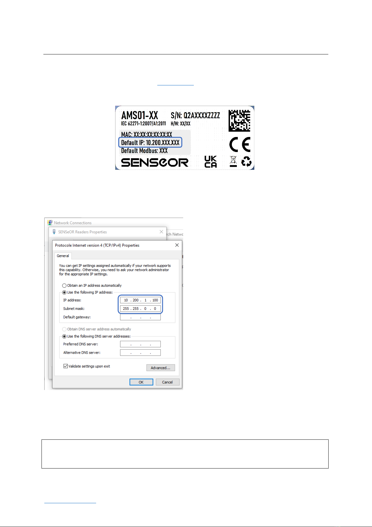
CONFIGURATION OF THE CONNECTION.............................................................................................. 8
APPLICATION LAUNCH..............................................................................................................................9
FIRST LAUNCH AND WINDOWS FIREWALL.......................................................................................... 9
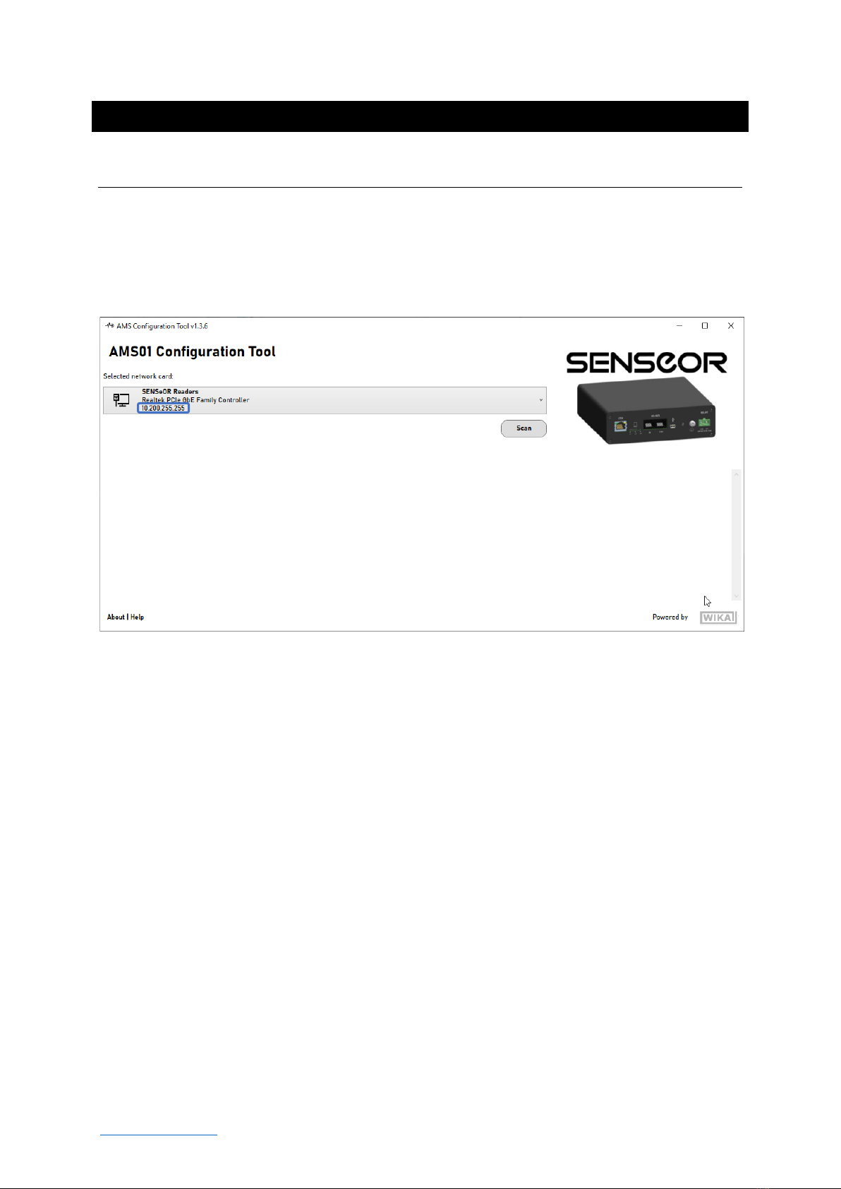
MAIN WINDOW DESCRIPTION ...............................................................................................................10
READER DETECTION........................................................................................................................... 10
READER WINDOW DESCRIPTION............................................................................................................12
SETTINGS TAB .................................................................................................................................... 12
INSTALLATION TAB ............................................................................................................................ 14
ENVIRONMENTAL SENSOR............................................................................................................. 14
TEMPERATURE INSTALLATION SETTINGS ...................................................................................... 14
ANTENNA PAIRS............................................................................................................................. 16
TEMPERATURE SENSORS................................................................................................................ 17
DIAGNOSTIC WINDOW................................................................................................................... 19
PARTIAL DISCHARGE PROBES......................................................................................................... 20
TEMPERATURE NOTIFIERS................................................................................................................. 21
NOTIFIER OPERATION .................................................................................................................... 21
TAB DESCRIPTION........................................................................................................................... 23
PARTIAL DISCHARGE NOTIFIERS ........................................................................................................ 24
NOTIFIER OPERATION .................................................................................................................... 24
TAB DESCRIPTION........................................................................................................................... 25
SYSTEM TEST TAB .............................................................................................................................. 26
TEST OF RELAY................................................................................................................................ 27
TEST OF THE TEMPERATURE SENSORS .......................................................................................... 27
TEST OF THE PARTIAL DISCHARGE PROBES ................................................................................... 27

MONITORING SOLUTION ENERGY
AMS01 Configuration Tool User Manual 6/29
www.senseor.com
OVERVIEW
This user manual describes how to use the AMS01 Configuration Tool software applicable with
AMS01-T,AMS01-P and AMS01-TP readers.
The following guidelines are applicable from version 1.3.6.
RELATED DOCUMENTS
-UM00403-EN_AMS01 User Manual.
-UM00417-EN_AMS01 Modbus table.
-UM00418-EN_AMS01 Modbus table with HTR02 compatibility mode.
-UM00419-EN_AMS01 SD card file management.
For additional related documentation and file downloads see support website at
senseor.com/downloads.
SYSTEM HARDWARE INSTALLATION
This manual provides details on the software installation and its configuration only, please refer to the
‘AMS01 User Manual’for specific hardware details.
WARNING
PROFESSIONAL INSTALLATION REQUIRED.
INSTALLATION AND CONFIGURATION SHOULD BE PERFORMED ONLY BY USERS WHO ARE
TECHNICALLY COMPETENT AND AUTHORIZED TO DO SO.
LOCAL REGULATIONS REGARDING ELECTRICAL INSTALLATION AND SAFETY MUST BE OBSERVED.
FAILURE TO FOLLOW THE GIVEN INSTRUCTIONS CAN RESULT IN DEATH OR IN SERIOUS INJURY.

MONITORING SOLUTION ENERGY
AMS01 Configuration Tool User Manual 7/29
www.senseor.com
CONFIGURATION TOOL INSTALLATION
OPERATING SYSTEM
The AMS01 Configuration Tool operates only on Microsoft Windows operating system, with at least
Windows 10 64-bit.
AMS01 CONFIGURATION TOOL INSTALLER
To install AMS01 Configuration Tool, double-click on the ‘Setup AMS01 Configuration Tool vX.Y.Z.msi’.
NOTE
THE LAST REVISION OF THE AMS01 CONFIGURATION TOOL IS AVAILABLE ON
WWW.SENSEOR.COM/DOWNLOADS.
Follow the Setup instructions to complete the installation.
OTHER REQUIRED INSTALLATION
NOTE
ADMINISTRATOR RIGHTS ARE REQUIRED TO INSTALL AND TO MANAGE THE NETWORK FIREWALL
SECURITY SETTINGS.
The AMS01 Configuration Tool requires Microsoft .NET 6.0. If the machine does not have Microsoft
.NET 6.0 installed, the installer can be found on the Microsoft website.

MONITORING SOLUTION ENERGY
AMS01 Configuration Tool User Manual 8/29
www.senseor.com
CONFIGURATION OF THE CONNECTION
The default IP address is printed on the serialization label on the back of the reader. This IP address
can be modified using the software (see ‘Settings’ tab)
To connect a computer to the reader, the Ethernet card must be configured as follows:
•IP address = 10.200.1.100
•Subnet mask = 255.255.0.0
NOTE
TO RESET IP OF THE AMS01 READER, HOLD THE RESET BUTTON UNTIL ALL LEDS ARE FLASHING GREEN.
THIS CAN TAKE UP TO 15 SECONDS.

MONITORING SOLUTION ENERGY
AMS01 Configuration Tool User Manual 9/29
www.senseor.com
APPLICATION LAUNCH
FIRST LAUNCH AND WINDOWS FIREWALL
At the first use of ‘Scan’button, the Windows firewall will ask for you about security notice.
You must allow the AMS01 Configuration Tool software to communicate using your networks.

MONITORING SOLUTION ENERGY
AMS01 Configuration Tool User Manual 10/29
www.senseor.com
MAIN WINDOW DESCRIPTION
READER DETECTION
At start-up, the application scans and lists available and active network adapters.
Select the network card associated with the readers IP address.
If the network card is not detected:
•Close the application,
•Check connection and configuration of the card in Windows settings,
•Restart the application.

MONITORING SOLUTION ENERGY
AMS01 Configuration Tool User Manual 11/29
www.senseor.com
Click on button to list readers connected to the selected card:
: Open reader window (see next chapter).
: Update firmware by loading firmware file (*.senseor) from file explorer.
: This label appears if the reader is in ‘Device Firmware Update (DFU)’mode.
NOTE
THE LATEST FIRMWARE VERSION IS AVAILABLE ON THE WEBSITE SENSEOR.COM/DOWNLOADS.
If a reader is not found:
•Reset the reader.
•Reset the reader’s Ethernet settings.
•Disable all VPN services on the computer.

MONITORING SOLUTION ENERGY
AMS01 Configuration Tool User Manual 12/29
www.senseor.com
READER WINDOW DESCRIPTION
SETTINGS TAB
This tab shows the reader information and could be used to configure the following settings:
-READER NAME (max 19 digits)
-SYSTEM
•Mains power frequency (‘50 Hz’ or ‘60 Hz’)
1
•System temperature unit (Celsius or Fahrenheit)
•Compatibility mode selection (‘AMS01’ or ‘HTR02’)
2
-ETHERNET
•IP address (IPv4 format)
•Subnet mask (IPv4 format)
•Default gateway (IPv4 format)
-RS485 MODBUS (RTU)
•Modbus address (from ‘1’ to ‘247’ – default value is printed on the reader label)
•Speed (default value is ’19 200’ bauds)
•Parity (default value is ‘None’)
•Stop bits (default value is ‘1’)
-TIME ZONE
1
Select the mains frequency of the measured electric system depending of your installation region (incorrect
selection could result in no detection of partial discharge).
2
Selecting HTR02 compatibility mode results in limitation of reader capacity as only antenna pairs 1 to 3. A
maximum of 6 sensors per antenna pairs are available for measurement. Compatibility mode could be used in
case of addition / replacement of existing HTR02 systems in order to keep the same Modbus table interface.

MONITORING SOLUTION ENERGY
AMS01 Configuration Tool User Manual 14/29
www.senseor.com
INSTALLATION TAB
This tab is used to configure temperature sensors and partial discharge detection probes installation.
For installation details, please refer to the ‘UM00403-AMS01 User Manual’.
ENVIRONMENTAL SENSOR
This location shows the information from the external humidity and temperature sensor if connected.
Data are obtain by click on the refresh button .
TEMPERATURE INSTALLATION SETTINGS
Only applicable for ‘AMS01-T’ and ‘AMS01-TP’ readers.
The AMS01 system needs a reference temperature for sensor validation.
This section allows use of different sources for temperature selection.

MONITORING SOLUTION ENERGY
AMS01 Configuration Tool User Manual 15/29
www.senseor.com
: Select which temperature reference must be used for sensor
installation.
Use Global Reference
Manually set temperature is used as reference
temperature.
Use Environmental Sensor
Environmental sensor temperature is used as reference
temperature.
Use Individual Reference
Temperature
The reference temperature must be manually set for each
sensor.
NOTE
THE LOCAL TEMPERATURE INFORMATION MUST BE ADJUSTED TO REFLECT SENSOR TEMPERATURE.

MONITORING SOLUTION ENERGY
AMS01 Configuration Tool User Manual 16/29
www.senseor.com
ANTENNA PAIRS
The AMS01 reader support up to five antenna pairs. Temperature sensors and partial discharge probes
needs to be configured for each antenna pair.
: Add new antenna to the reader configuration.
: Clear all antennas from the reader configuration.
: Remove the antenna from the reader configuration.
: Enter a panel location name (max 19 digits).
: Enter a compartment location (max 19 digits).

MONITORING SOLUTION ENERGY
AMS01 Configuration Tool User Manual 17/29
www.senseor.com
TEMPERATURE SENSORS
The following picture shows the temperature sensor configuration section in antenna pair.
: Add sensor(s) by selecting XML file(s) into the antenna pair.
: Name of the sensor (max 19 digits).
: Check the sensor.
: Enter the reference temperature (only available when Individual reference
temperature use is selected in Temperature installation settings space).
: Open diagnostic window (see next section –only available when check has
been made).
: Select a temperature Notifier to associate with the sensor (see ‘Temperature
monitoring notifiers’ chapter).
: Remove the sensor from the antenna pair.
Modbus addresses are assigned to sensors following order of configuration. In case of you need
respect a specific Modbus mapping, please take care of the order while you add sensors to the
antenna pair.
Check status
The Check button, will perform an interrogation of the sensor. This operation could take up to 20
seconds. Check status Led indicates if sensor installation permit correct interrogation by the reader.
: No check has been performed.
: The sensor does not meet measurement criteria and cannot be commissioned.
: The sensor does not meet minimal measurement criteria and requires manual
commissioning.
: The sensor meets all measurement criteria and is automatically commissioned
by the system.

MONITORING SOLUTION ENERGY
AMS01 Configuration Tool User Manual 18/29
www.senseor.com
Commissioning status
The commissioning status information reflects the status of the sensor view by the reader. A non-
commissioned sensor will not be interrogated by the reader.
: The sensor is commissioned by the system on the best RF signal available.
: The sensor is commissioned manually from the diagnostic page.
: The sensor is not commissioned.

MONITORING SOLUTION ENERGY
AMS01 Configuration Tool User Manual 19/29
www.senseor.com
DIAGNOSTIC WINDOW
Only applicable for ‘AMS01-T’ and ‘AMS01-TP’ readers.
This window shows the spectrum view of the sensitive elements of a temperature sensor and more
precise information about sensor interrogation result.
The system will suggest an operating point validating most of its criteria. If needed you can select an
other operating point.
: Select desired operating point.
: Commission the sensor with selected operating point.

MONITORING SOLUTION ENERGY
AMS01 Configuration Tool User Manual 20/29
www.senseor.com
PARTIAL DISCHARGE PROBES
Only applicable for ‘AMS01-P’ and ‘AMS01-TP’ readers.
: Click to enable/disable the PD probe for this antenna pair.
: Select a PD Notifier to associate with the probe (see ‘Partial discharge
monitoring notifiers’ chapter).
Other manuals for SENSeOR AMS01
2
Table of contents
Other WIKA Accessories manuals