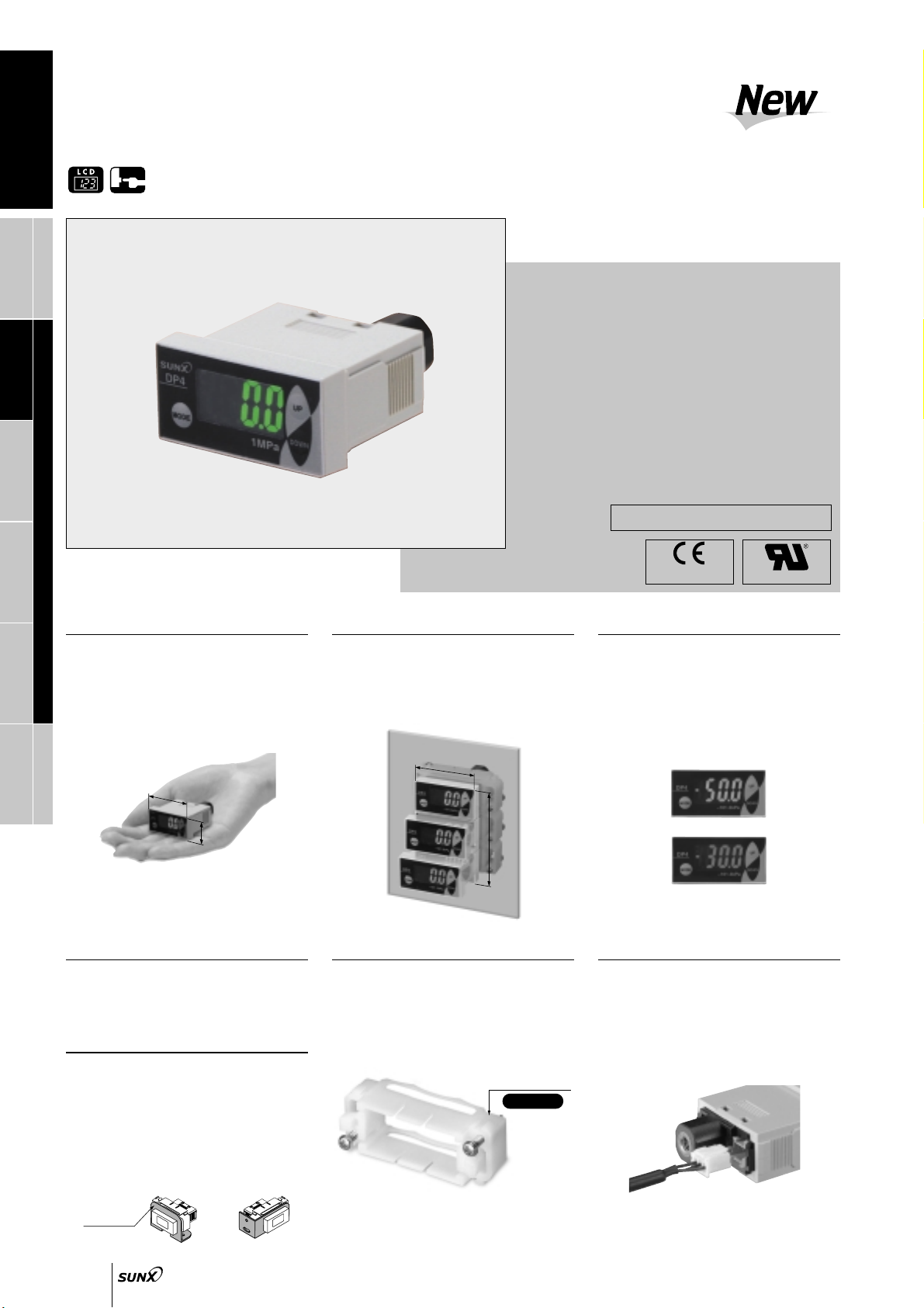
PRESSURE SENSORS
DP5/DPH
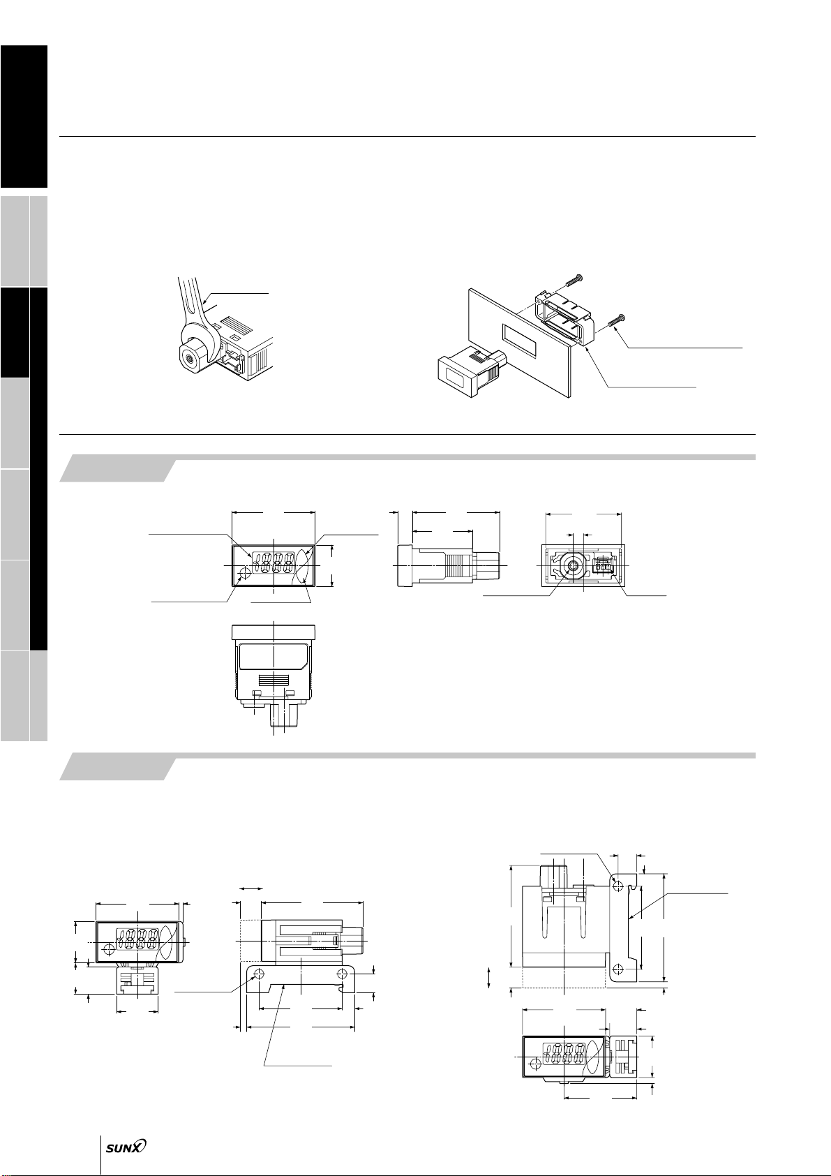
Head-separated
DP4DP2DP3DP-M Digital Display
PE
LED Bar Display
DP4
783
Gauge pressure
0 to 101.3 kPa 0 to 1.000 MPa 100.0 to 100.0 kPa
5.1 to 101.3 kPa
0.052 to1.033 kgf/cm
2
, 0.051 to1.013 bar
0.74 to14.70 psi, 38 to760 mmHg
1.5 to29.9 inHg
490 kPa 1.470 MPa 490 kPa
Non-corrosive gas
1 digit (however, variable in hysteresis mode)
Within 0.2 % F.S. 1 digit (within 3 digits)
12 to 24 V DC % Ripple P-P 10 % or less
40 mA or less
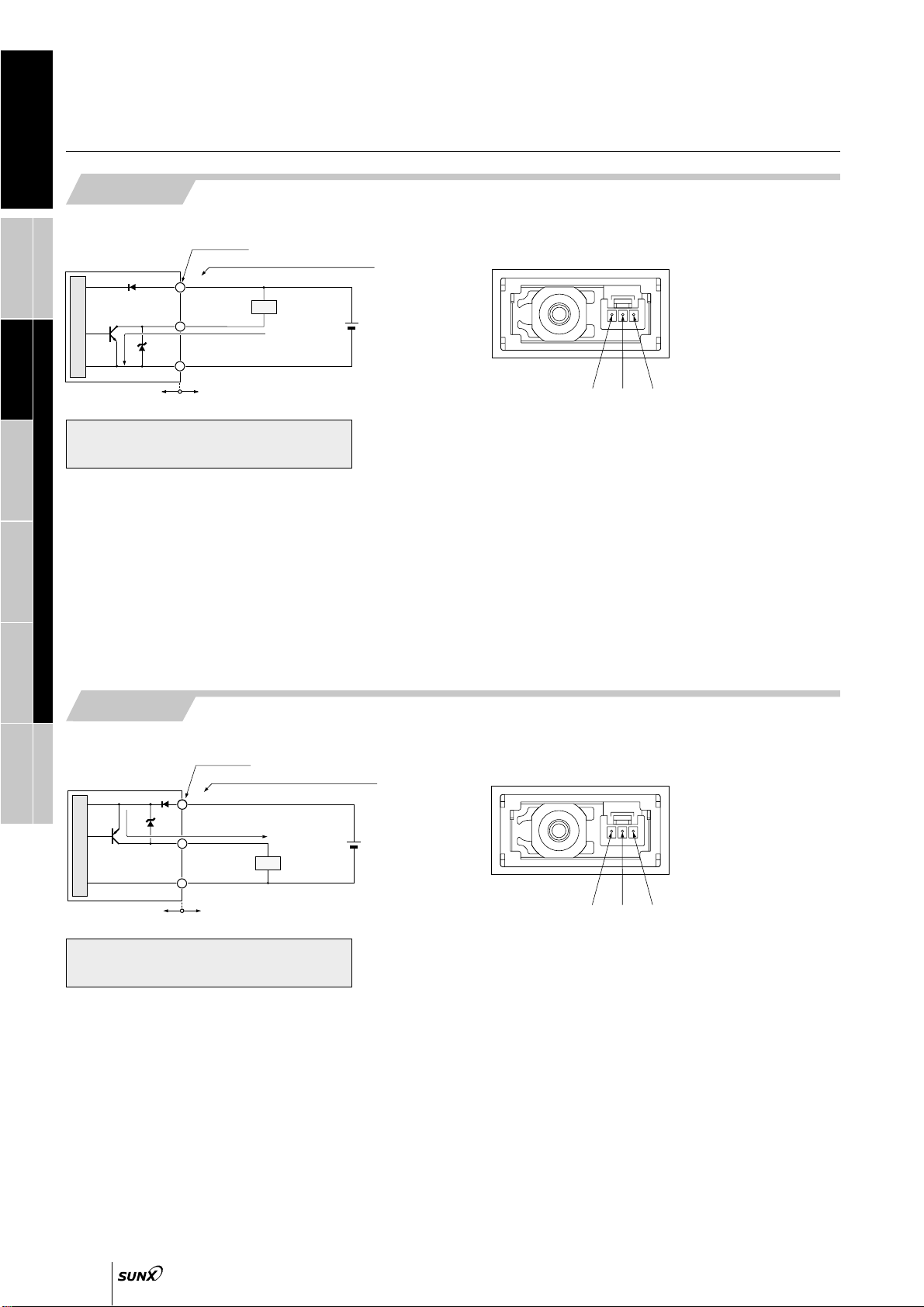
<NPN output type>
NPN open-collector transistor
• Maximum sink current: 100 mA
• Applied voltage: 30 V DC or less (between output and 0 V)
• Residual voltage: 1 V or less (at 100 mA sink current)
0.4 V or less (at 16 mA sink current)
DC-12 or DC-13
NO / NC (selectable by key operation)
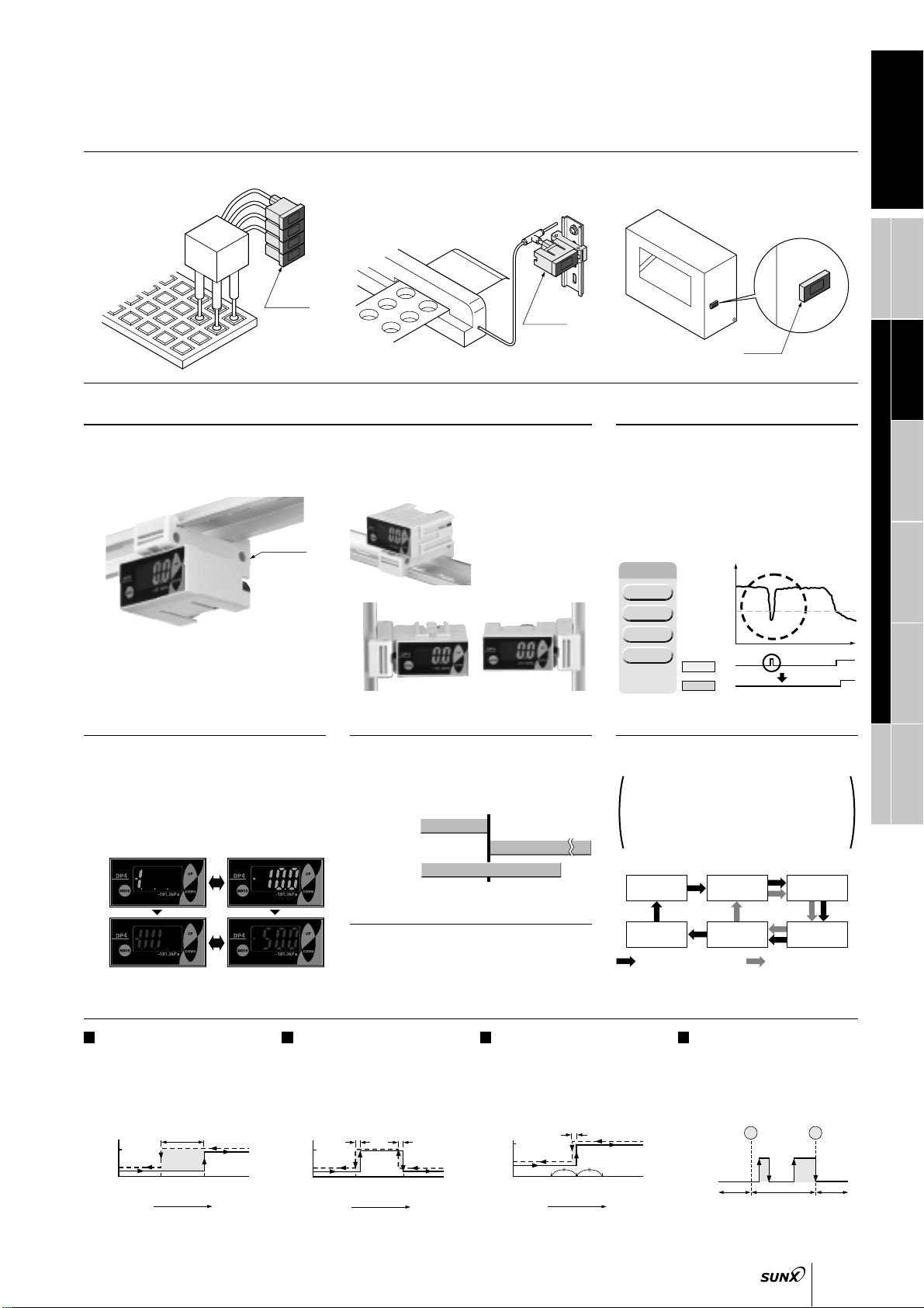
Equipped with 4 types of modes: Hysteresis mode, window comparator mode, automatic sensitivity setting mode,
forced output mode (selectable by key operation)
Incorporated
2 ms, 16 ms, 128 ms, 512 ms or less (selectable by key operation)
31/2digit LCD display (with red and green backlight)
(Sampling rate: 256 ms, 512 ms, 1,024 ms selectable by key operation)
5.1 to 101.3 kPa
0.052 to1.033 kgf/cm
2
, 0.051 to1.013 bar
0.74 to14.70 psi, 38 to760 mmHg
1.5 to29.9 inHg
Bar display in steps of 14 % F.S. approx.
LCD segment is red when the output is ON, and green when the output is OFF
3 (Industrial environment)
IP40 (IEC)
0 to50 C 32 to122 F(No dew condensation), Storage: 10 to60 C 14 to140 F
35 to 85 % RH, Storage: 35 to 85 % RH
EN 50081-2, EN 50082-2, EN 61000-6-2
1,000 V AC for one min. between all supply terminals connected together and enclosure
50 MΩ, or more, with 500 V DC megger between all supply terminals connected together and enclosure
10 to 150 Hz frequency, 0.75 mm 0.030 in amplitude, or 5 G in X, Y and Z directions for two hours each
100 m/s2acceleration (10 G approx.) in X, Y and Z directions for three times each
Over ambient temperature range 10 to40 °C 50 to104 °F: within 2 % F.S. of detected pressure at 25 °C 77 °F
Over ambient temperature range 0 to50 °C 32 to122 °F: within 5 % F.S. of detected pressure at 25 °C 77 °F
M5 female thread
Front case: ABS, LCD display: PET, Rear case: PBT [M5 threaded part: Brass (nickel plated)]
Connector
0.16 to 0.32 mm2 (AWG#25 to 22)
"1.2 to "1.8 mm "0.047 to "0.071 in
Tin plated, soft, twisted copper wire
Extension up to total 100 m 328.084 ft (less than 10 m 32.808 ft when conforming to CE marking) is possible with 0.3 mm
2
, or more, cable
30 g approx.
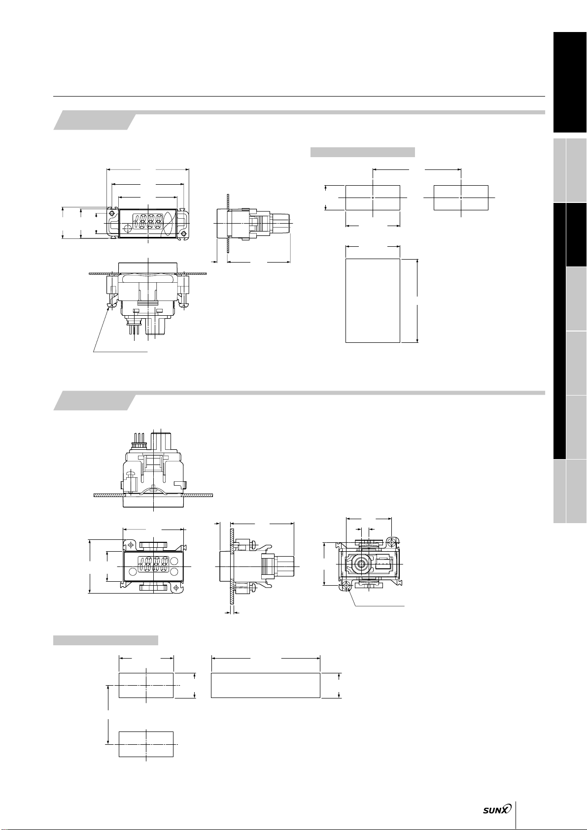
Panel mounting bracket (MS-DP-1): 1 set, Pressure unit label: 1 pc.
Connector: 1 set (Housing: 1 pc., Connector pin: 3 pcs.)
SPECIFICATIONS
10
15
<PNP output type>
PNP open-collector transistor
• Maximum source current: 100 mA
•
Applied voltage: Same as supply voltage (between output and
V)
• Residual voltage: 2 V or less (at 100 mA source current)
Within 0.2 % F.S. 2 digits
(within 6 digits)
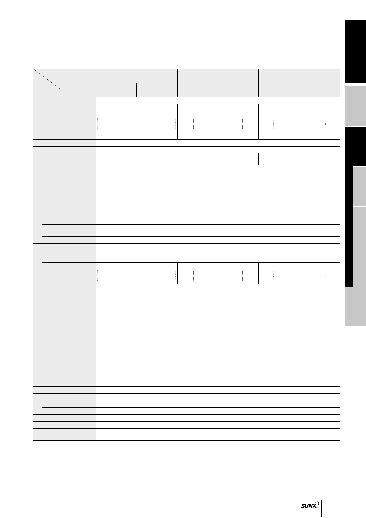
Type of pressure
Rated pressure range
Set pressure range
Pressure withstandability
Applicable fluid
Hysteresis
Repeatability
Supply voltage
Current consumption
Output
Utilization category
Output operation
Output modes
Short-circuit protection
Response time
Display
Displayable pressure range
Analog bar display
Operation display
Pollution degree
Protection
Ambient temperature
Ambient humidity
EMC
Voltage withstandability
Insulation resistance
Vibration resistance
Shock resistance
Temperature characteristics
Pressure port
Material
Connecting method
Conductor cross-section area (Note)
Lead wire diameter
Wire material
Cable extension
Weight
Accessories
Suitable cable
Environmental resistance
Vacuum pressure Positive pressure Compound pressure
101 kPa type 1 MPa type 100 kPa type
NPN output PNP output NPN output PNP output NPN output PNP output
DP4-50 DP4-50P DP4-52 DP4-52P DP4-57 DP4-57P
Type
Item Model No.
Note: If the wiring is longer than 5 m 16.404 ft, use a cable with a diameter of 0.3 mm2or more.
0.050 to 1.050 MPa
0.51 to 10.71 kgf/cm2
0.50 to 10.50 bar
7.2 to 152.2 psi
0.050 to 1.050 MPa
0.51 to 10.71 kgf/cm2
0.50 to 10.50 bar
7.2 to 152.2 psi
101.3 to 105.0 kPa
1.033 to 1.071 kgf/cm2
1.013 to 1.050 bar
14.68 to 15.22 psi
101.3 to 105.0 kPa
1.033 to 1.071 kgf/cm2
1.013 to 1.050 bar
14.68 to 15.22 psi