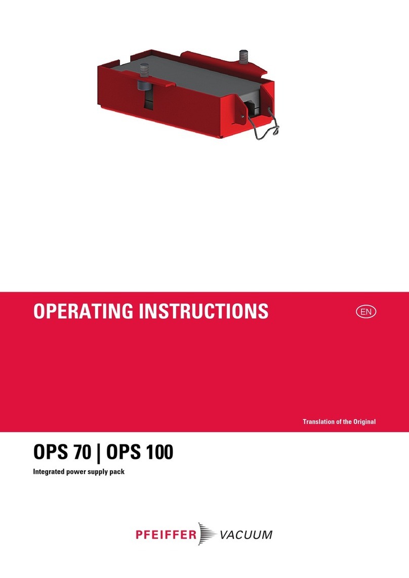
Pfeiffer Vacuum TPS 100 User manual

Power Supply
PM 800 521 BE/I (0311)
TPS 100 – 600
TPS 101 – 601
Betriebsanleitung • Operating Instructions

2
Index
Page Page
1. Safety Instructions .................................. 2
1.1. For Your Orientation........................................................... 2
1.2. Pictogram Definitions........................................................ 2
2. Understanding The Power Supplys ....... 3
2.1. Main Features..................................................................... 3
Proper Use .......................................................................... 3
Improper Use ...................................................................... 3
3. Installation ............................................... 4
3.1. Connection To The Mains................................................. 4
3.2. Assembly ............................................................................. 4
1. Safety Instructions
☞Read and follow all instructions in this manual.
☞Inform yourself regarding:
– Hazards which can be caused by the power supply;
– Hazards which can be caused by your system.
☞Observe the safety and accident prevention regulations.
☞Regularly check that all accident prevention measures are
being complied with.
☞Do not carry out any unauthorised conversions or
alterations to the power supply.
☞The TPS 300/301 and TPS 600/601 power supply output
voltages are dangerous to touch. Only use original
connecting cable for connection to the TC. The power
supply is designed according to protection class I. It must
have a connection with advanced earthed conductor
contact (PE).
☞When returning the power supply please note the shipping
instructions in Section 4.
Modifications reserved.
Warning, danger of personal injury.
WARNING
Caution, danger of damage to the power supply
or to the system.
CAUTION
1.1. For Your Orientation
Instruction in the text
➡Working instruction: Here, you have to do something.
Abbreviations used
DCU = Display and operating unit
TC = Electronic drive unit, turbopump
TPS = Power supply
1.2. Pictogram Definitions
4. Maintenance/Service.............................. 5
5. Technical Data ......................................... 5
5.1. Dimensions.......................................................................... 6
Manufacturer’s Declaration........... (last page)
PPlleeaasseennoottee::Current operating instructions are available via
www.pfeiffer-vacuum.de/Infoservice.
Please note, attention to particulary important
information on the product, handling the
product or to a particular part of the documen-
tation.
☞
PLEASE NOTE

3
2.1. Main Features
2. Understanding The Power Supplys
power supplys are used to supply voltage to Pfeiffer Vacuum
turbomolecular pumps with integrated Electronic Drive
Units TC.
The output voltage is safely separated from the mains voltage
in compliance with the European Industrial Standard
EN 60 742.
Power supplys are available in the following versions:
– For wall and standard runner fitting
(TPS 100, 150, 200, 300, 600)
– As a 19” insert unit
(TPS 101, 201, 301, 601)
– As a 19” insert unit with the Display Control Unit [DCU]
(please see separate Operating Instructions
PM 800 477 BN for the DCU)
Proper use
– Power supplys may only be used to supply voltage to
Pfeiffer Vacuum turbomolecular drag pumps integrated
with Electronic Drive Units TC.
– Only those versions of the power supply listed here may be
used.
– Power supplys may only be used under the operating
conditions set out in Section 5. Technical Data.
Improper use
The following is regarded, inter alia, as improper:
– The use for purposes not covered above, in particular:
– For connection to pumps and units which, according
to their operating instructions, do not provide for
such connection;
– For connection to units where touchable, voltage
carrying parts are involved.
Improper use will cause all claims for liability and guarantees
to be forfeited.
MMaaiinnssccaabblleeOOrrddeerrnnuummbbeerr
Schuko plug (230 V) P 4564 309 ZA
UL-plug (208 V) P 4564 309 ZF
UL-plug (115 V) P 4564 309 ZE
Power supply rear panel, TPS 300/301 as an example
X1 Connection to the mains
X2 Connection to the Electronic Drive Unit TC
F1 Fuse
F2 Fuse
S1 ON/OFF switch
S1 X1
F1
F2
X2
Mains voltage is supplied via a mains cable with the following
optional plugs:
PPoowweerrssuuppppllyyssffoorrwwaallllaannddOOrrddeerrNNuummbbeerr
ssttaannddaarrddrruunnnneerrffiittttiinngg
TPS 100 PM 041 827 -T
TPS 150 PM 051 461 -T
TPS 200 PM 041 813 -T
TPS 300 PM 041 814 -T
TPS 600 PM 041 815 -T
PPoowweerrssuuppppllyyssaassaa
1199””iinnsseerrttuunniitt
TPS 101 PM 041 828 -T
TPS 201 PM 041 819 -T
TPS 301 PM 041 820 -T
TPS 601 PM 041 821 -T

4
3. Installation
105
105e
105a
105c
105d
105f
105b
C40-908/1
Installing the power supplys
105 Power Supply TPS
105a Wall attachment plate
105b Front panel
105c Standard runner holder
105d Screw (M2.9 x 6.5; German Industrial Standard 7982)
105e Screw (M3 x 8; German Industrial Standard 966)
105f Screw (M2.2 x 10; German Industrial Standard 7983)
3.1. Connection To The Mains
Do not carry out any unauthorised conversions or
alterations to the power supply.
The power supply should be connected to the
mains in accordance with local regulations. Plea-
se refer to the technical data for the connection
voltage ranges of the individual units. Protection
type IP 20 applies to the units.
➡Plug mains connection cable into mains connection X1 (plea-
se see 2.1.).
3.2. Assembly
Power Supplys TPS 100, TPS 150, TPS 200, TPS 300 and TPS 600
FFiittttiinnggtthheeTTPPSSttoowwaallllss
➡Screw wall attachment plate 105a to the side panel of the
TPS with the set of screws 105d provided.
➡Secure the power supply to the wall (for dimensions please
see 5.1.).
➡Ensure adequate air circulation.
FFiittttiinnggtthheeTTPPSSttoossttaannddaarrddrruunnnneerrss
➡Screw the standard runner clamping part 105c (included)
with ever two screws 105f to wall attachment plate 105a.
➡Screw the wall attachment plate to the side panel of the TPS
with enclosed srew set 105d.
➡Ensure adequate air circulation.
Do not use screws longer than 105d (6.5 mm)for
wall and standard runner fitting on account of the
danger of short circuits.
CAUTION
CAUTION
WARNING
Inserting into a 19”/3HE rack
When fitting, free circulation must be ensured.
The minimum distance to the cooling openings
above and below is ≥50 mm.
Power Supplys TPS 101, TPS 201 and TPS 301
➡Unscrew the two screws from the front of the
Power Supply TPS.
➡Screw front panel 105b to the power supply using
screws 105e provided.
➡Insert the power supply into the rack and secure.
PPoowweerrSSuuppppllyyTTPPSS660011
➡Insert the Power Supply TPS 601 into the rack and
secure.
☞
PLEASE NOTE

5
5. Technical Data
4. Maintenance/Service
No maintenance is required on the power supply.
No liability for personal injury nor material
damage will be accepted for damages and
operational interruptions which have been
caused by improper maintenance; in addition,
all guarantees become invalid.
Do make use of our service facilities
In the event that repairs are necessary to your power supply,
a number of options are available to you to ensure any system
down time is kept to a minimum:
– Return the unit to the manufacturer for repairs.
– Replace the unit with a new value exchange unit.
☞
PLEASE NOTE
Local Pfeiffer Vacuum representatives can provide full
details.
Repair orders are carried out according to our
general conditions of sale and supply. If repairs
are necessary, please send the pump to your
nearest Pfeiffer Vacuum Service Center.
Contact addresses and telephone hotline
Contact addresses and telephone numbers can be found on
the back cover of these operating instructions.
☞
PLEASE NOTE
1) Mains with earthed conductor
FFeeaattuurreeUUnniittTTPPSS110000//110011TTPPSS115500TTPPSS220000//220011TTPPSS330000//330011TTPPSS660000//660011
Connection voltage VAC 90-132 185-265 90-132 185-265 90-132 185-265 90-132 185-265 90-132 185-265
Frequency Hz 50-60 50-60 50-60 50-60 50-60
Max. power consumption VA 125 170 230 350 590 900
Protection class1) II I I I
Output voltage VDC 24 24 48 72 140
Continuous-/max. output current A 4.1/4.6 5/6.2 4.1/4.6 4.1/4.6 3.8/4.4 5.8/6.6
Continuous-/max. output power W 100/110 120/150 200/220 230/300 530/616 812/924
Permissible ambient
temperature °C 5-40 5-40 5-40 5-40 5-40
Relative humidity, max.
at 35 °C % 80 80 80 80 80
at 40 °C % 50 50 50 50 50
Protection system IP 20 IP 20 IP 20 IP 20 IP 20
Fuse 5 x 20 mm A T2 T4 T4 T5 F10
Weight kg 1.2 1.4 1.4 1.7 2.5

6
5.1. Dimensions
1) TE = Rack design partitions, 19” German Industrial Standard DIN 41 488 is divided into 84 partitions.
G7.5
7.5
122.5 3
3
C
D
A
B
E
F
TPS
DDiimmeennssiioonnss(mm)
PPoowweerrSSuuppppllyyAABBCCDDEEFFGG
TTPPSS110000//110011190 192,5 128,5 106 46 50,5 (10 TE)1) 35,5
TTPPSS115500190 192,5 128,5 106 68 70,8 (14 TE)1) 55,9
TTPPSS220000//220011190 192,5 128,5 106 68 70,8 (14 TE)1) 55,9
TTPPSS330000//330011190 192,5 128,5 106 105 106,3 (21 TE)1) 91,4
TTPPSS660000//660011229 229 128,5 111 140,5 141,9 (28 TE)1) 127
190
120
142
130
Wall attachment

im Sinne folgender EU-Richtlinien:
pursuant to the following EU directives:
- Maschinen/Machinery 98/37/EWG (Anhang/Annex II B)
- Elektromagnetische Verträglichkeit/Electromagnetic Compatibility
89/336/EWG
- Niederspannung/Low Voltage 73/23/EWG
Hiermit erklären wir, daß das unten aufgeführte Produkt zum Einbau in eine Maschine bestimmt ist und
daß deren Inbetriebnahme so lange untersagt ist, bis festgestellt wurde, daß das Endprodukt den
Bestimmungen der EU-Richtlinie 98/37/EWG entspricht.
Das unten aufgeführte Produkt entspricht den Anforderungen der EU-Richtlinien Maschinen
98/37EWG, Elektromagnetische Verträglichkeit 89/336/EWG und Niederspannung 73/23/EWG.
We hereby certify that the product specified below is intended for installation in a machine which is
forbidden to be put into operation until such time as it has been determined that the end product is in
accordance with the provision of EU Directive 98/37/EEC.
The product specified below is in correspondence to the EU directives Machinery 98/37/EEC, Electro-
magnetic Compatibility 89/336/EEC and EU Low Voltage 73/23/EEC.
Produkt/Product:
TPS 100 – 600
TPS 101 – 601
Angewendete Richtlinien, harmonisierte Normen und angewendete nationale Normen:
Guidelines, harmonised standards, national standards in which have been applied:
EN 60742, EN 61010, EN 55011, EN 50081-1, EN 50082-2,
IEC 801 1-4, VDE 0843-6
Unterschrift/Signature:
Unterschriften:
(W. Dondorf)
Geschäftsführer
Managing Director
Pfeiffer Vacuum GmbH
Berliner Str. 43
35614 Asslar
Germany
Herstellererklärung
Manufacturer´s Declaration
Herst.I/2003

Pfeiffer Vacuum Technology AG · Headquarters/Germany
Tel. +49-(0) 64 41-8 02-0 · Fax +49-(0) 64 41-8 02-2 02 · [email protected] · www.pfeiffer-vacuum.net
Your Vacuum Technology Experts in
Turbo Pumps
Rotary Vane Vacuum Pumps
Roots Pumps
Dry Vacuum Pumps
Leak Test Units
Valves
Flanges, Feedthroughs
Vacuum Measurement
Gas Analysis
System Technology
Service
This manual suits for next models
8
Table of contents
Other Pfeiffer Vacuum Power Supply manuals
Popular Power Supply manuals by other brands

Agilent Technologies
Agilent Technologies E3632A Service guide

Allied Telesis
Allied Telesis AT-PWR01 installation guide

Keysight
Keysight E3633A user guide

Circuit Specialists
Circuit Specialists CSI12005S quick start guide

AXSOL
AXSOL ARVEY E-Series User manual and warranty statement

AFi
AFi PSR-5 instruction manual