Pfeiffer Vacuum PS 115 User manual

BG 5036 BEN / A
(
2016-07
)
O
P
P
O
PE
R
P
S 1
1
P
ressure
S
R
ATI
1
5, S
V
S
witch, Dif
f
NG I
N
V
11
0
f
erential Pr
N
ST
R
0
e
ssure Ad
a
R
UC
T
a
pter, Swi
t
T
ION
S
t
ching Am
p
S
p
lifie
r
Transl
a
a
tion of the original
instructions

2BG 5036 BEN / A (2016-07) PS115_SC110.oi
In all communications with Pfeiffer Vacuum, please specify the information on the
product nameplate. For convenient reference copy that information into the space
provided below.
This document applies to products with part numbers
PT R02 110 (PS 115 Pressure Switch)
PT 120 171 -T (Differential Pressure Adapter)
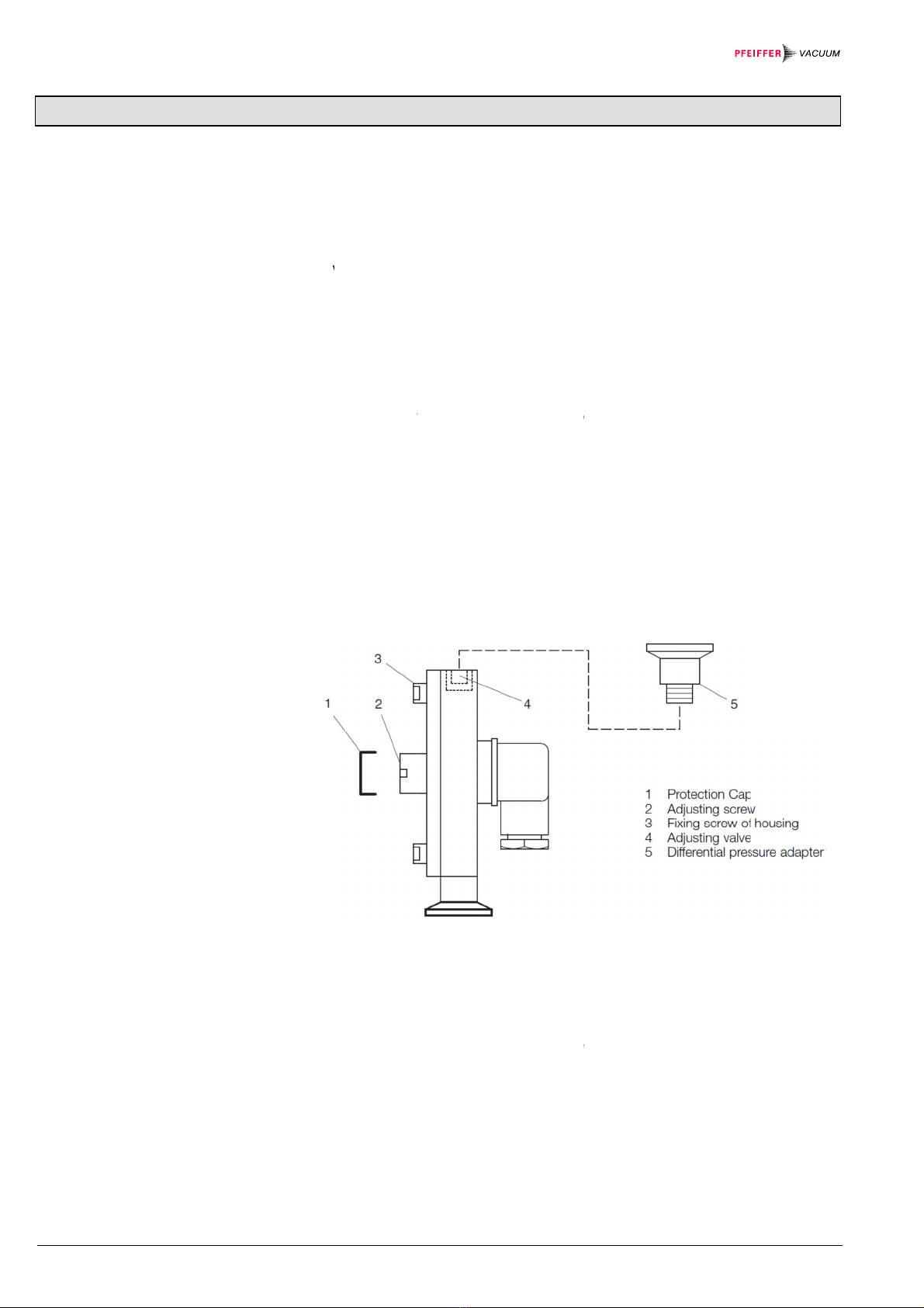
PT 120 172 (Pressure switch adjustment)
PT R02 111 (SV 110 Switching amplifier)
The part number (No:) can be taken from the product nameplate.
We reserve the right to make technical changes without prior notice.
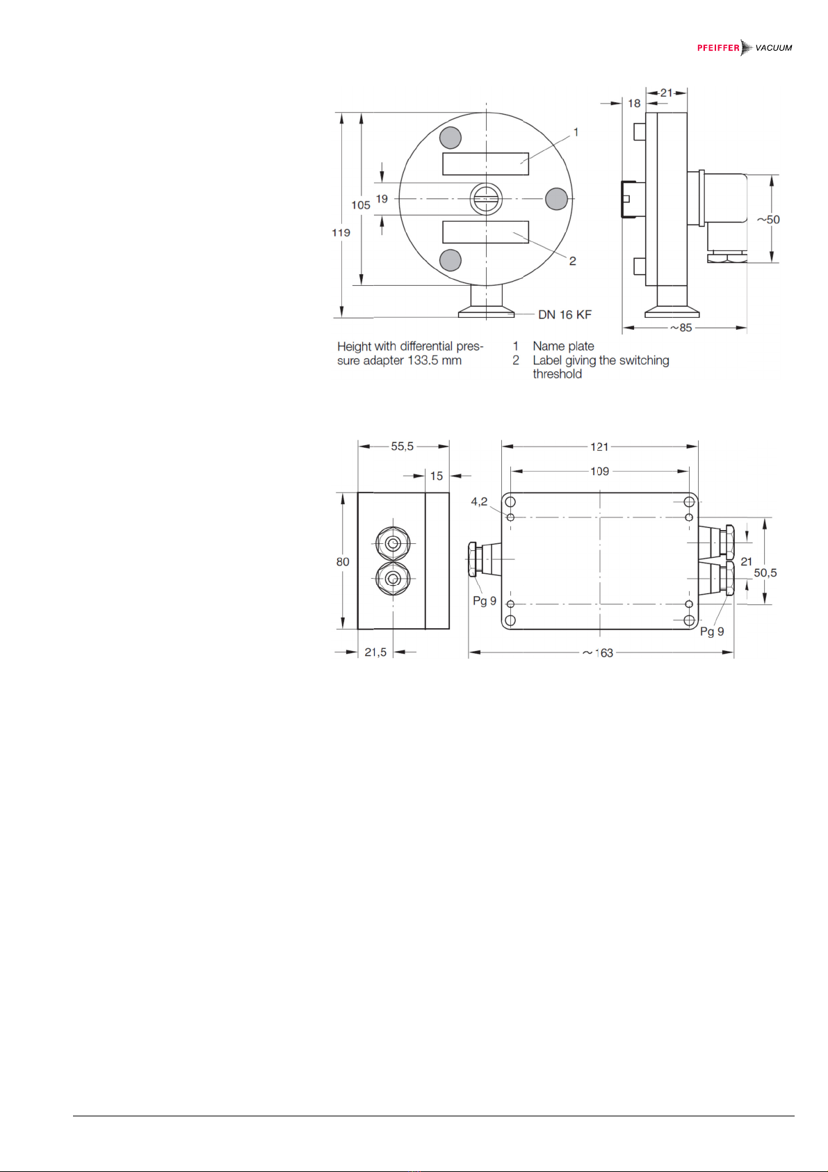
All dimensions in mm.
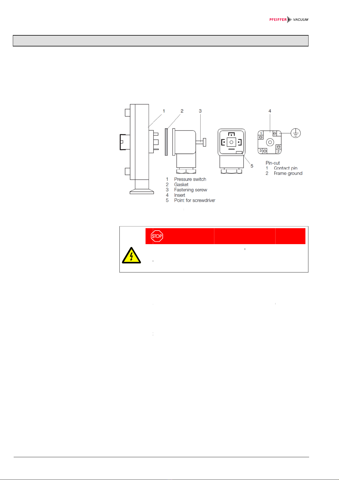
The references to diagrams, e.g. (4/5), consist of the fig. no. and the item no. in
that order.
The pressure switch PS 115 in connection with the switching amplifier SV 110 is
used to produce pressure dependent signals and for the control of valves and
pumps.
The pressure switch PS 115 can also be used as a differential pressure switch.
Unpack the pressure switch and the switching amplifier immediately after delivery,
even if they are to be put into operation at a later date.
Before doing so, examine the shipping container for any external damage.
Then completely remove the packaging materials.
The shipping container and packaging materials must be kept in the event of
complaints about damage.
Check for completeness.
Carefully examine the pressure switch and the switching amplifier visually.
If any damage is discovered, report it immediately to the forwarding agent and in-
surer. If the damaged part has to be replaced, please get in touch with the orders
department.
The PS 115 is a diaphragm absolute pressure switch. He can also be used as a
differential pressure switch.
Within both pressure switches there is a sensing chamber (1/2) and a reference
chamber (1/5) separated by a highly sensitive sealed diaphragm made of stainless
steel (1/3). A pin (1/6) in the reference chamber (1/5) is led to the outside and
insulated (1/7). The ground connected diaphragm acts as the opposite contact.
This contact configuration is so designed that the diaphragm contacts the pin when
it is unstressed, i. e. with equal pressure in sensing and reference chamber.
Product Identification
Validity
Description
Unpacking and Checking
Design and Function

BG 5036 BEN / A (2016-07
)
Pressure
Operatio
n
Switchin
g
Operatio
n
Supplied
)
PS115_SC110.oi
Switch M
o
n
g
Amplifie
n
Equipme
n
o
de of
r Mode o
f
n
t
For swi
t
and ref
e
ing pre
s
referen
c
heavy-
d
A switc
h
plied wi
t
below t
h
phragm
phragm
diaphra
g
built-in
s
Fig 1 S
c
•Pre
s
•Swi
t
f
t
ch-point setti
n
e
rence cham
b
s
sure is attain
e
c
e pressure b
y
d
uty relay in t
h
h
ing amplifier
t
h heavy-duty
h
e value pres
e
and contact
p
. The SV 110
g
m pressure
s
s
lide switch (
F
c
hematic diag
s
sure switch
P
t
ching amplifi
e
n
g, the adjusti
b
er (1/5) is op
e
e
d. If the pres
y
more than 0
h
e connected
S
is required fo
r
change-over
e
t on the pres
s
p
in in the refe
r
switching am
s
witches, Cat.
F
ig. 5) must b
e
ram of the pr
e
P
S 115 or
e
r SV 110
ng valve (1/4
)
e
ned and clos
e
s
ure in the se
.1 mbar, the
c
S
V 110 switc
h
r
each pressu
r
contact is en
e
s
ure switch, i.
r
ence chamb
e
p
lifier is also
s
Nos. 164 04
t
e
set to the co
e
ssure switch
e
)
between se
n
ed again whe
e
nsing chamb
e
c
ontact opens
h
ing amplifier.
re switch. Th
e
e
rgized when
e. if the cont
a
e
r opens by fl
e
s
uitable to op
e
to 164 07 (ol
d
o
nnected type
e
s
n
sing chambe
r
n the desired
e
r drops belo
w
and energize
e
output relay
the pressure
d
a
ct bet- ween
d
e
xing of the di
a
e
rate the SM
4
d
er versions).
T
of pressure s
w
3
r
(1/2)
switch-
w
the set
s a
sup-
d
rops
d
ia-
a
-
4
2
T
he
w
itch.

4BG 5036 BEN / A (2016-07) PS115_SC110.oi
Contents
Product Identification 2
Validity 2
Description 2
Unpacking and Checking 2
Design and Function 2
Pressure Switch Mode of Operation 3
Switching Amplifier Mode of Operation 3
Supplied Equipment 3
Contents 4
1Safety 5
1.1 Symbols Used 5
1.2 Personnel Qualifications 5
1.3 General Safety Instructions 5
1.4 Liability and Warranty 5
2Technical Data 6
3Installation 8
3.1 Connection to the Vacuum System 8
3.2 Electrical Connection 8
3.2.1 Connection of the Pressure Switch 8
3.2.2 SV 110 Switching Amplifier 9
4Operation 10
4.1 Design Versions and Switch Point Setting 10
4.2 Differential Pressure Adapter 11
4.3 Typical Applications 12
4.3.1 Protection of a Gate Valve which must only be Operated when Pressure
on both Sides Becomes Equal 12
4.3.2 In a Vacuum System it must be Prevented that in Case of Failure Gas
Flows into the Vacuum Chamber 12
4.3.3 Automatic Venting of a Vacuum Chamber 12
4.3.4 Automatic Venting of a Vacuum Chamber to a Slight Overpressure 12
4.3.5 Differential Pressure Monitoring, Positive and Negative Going 13
5Maintenance 14
5.1 Cleaning the Sensing Chamber 14
5.2 Cleaning the reference chamber 14
6Wearing Parts and Original Spare Parts 15
7Accessories 15
8Returning the Product 16
9Disposal 16
Appendix 17
A: Conversion Table 17
EU Declaration of Conformity 18
For cross-references within this document, the symbol (→XY) is used.

BG 5036 BEN / A (2016-07) PS115_SC110.oi 5
1 Safety
DANGER
Information on preventing any kind of physical injury.
WARNING
Information on preventing extensive equipment and environmental damage.
Caution
Information on correct handling or use. Disregard can lead to malfunctions or
minor equipment damage.
Notice
Skilled personnel
All work described in this document may only be carried out by persons who
have suitable technical training and the necessary experience or who have been
instructed by the end-user of the product.
•Adhere to the applicable regulations and take the necessary precautions for the
process media used.
Consider possible reactions with the product materials (→6).
•Adhere to the applicable regulations and take the necessary precautions for all
work you are going to do and consider the safety instructions in this document.
•Before beginning to work, find out whether any vacuum components are conta-
minated. Adhere to the relevant regulations and take the necessary precautions
when handling contaminated parts.
Communicate the safety instructions to all other users.
Pfeiffer Vacuum assumes no liability and the warranty is rendered null and void if
the end-user or third parties
•disregard the information in this document
•use the product in a non-conforming manner
•make any kind of interventions (modifications, alterations etc.) on the product
•use the product with accessories not listed in the corresponding product docu-
mentation.
1.1 Symbols Used
Symbols for residual risks
1.2 Personnel Qualifications
1.3 General Safety
Instructions
1.4 Liability and Warranty

6BG 5036 BEN / A (2016-07) PS115_SC110.oi
2 Technical Data
Switching range 0.5 to 2000 mbar
Overload limit 3000 mbar
Response sensitivity 0.1 mbar
Switching hysteresis 0.5 mbar
Temperature coefficient 0.4 % /K of switching value
Ambient temperature
briefly (max. 8 h)
continuous
120 °C
90 °C
Switching voltage 24 V
Switching current 10 mA
Connector protected plug (DIN 43 650)
Protection type (DIN 40 050) IP 65
Vacuum connection DN 16 KF
Materials in contact with the medium
Sensing volume stainless steel 1.4301, 1.4401, 1.4310,
1.3541, FPM
Reference volume stainless steel 1.4301, 1.4401, 1.3541,
glass; gold
Sensing volume, approx.
including connection port
ca. 4 cm3
Reference volume, approx. ca. 20 cm3
Weight 1.3 kg
Mains supply 110 to 130 V
220 to 240 V
Mains frequency 50/60 Hz
Power consumption 3 VA
Output relay
Switching voltage, max.
Switching current, max.
Switching capacity, max.
250 V
5 A
500 V
Response time 30 ms
Release time 7 ms
Control circuit 24 V / 10 mA
Ambient temperature, max. 50 °C
Weight 0.36 kg
Pressure Switch PS 115
SV 110 Switching Amplifier

BG 5036 BEN / A (2016-07
)
Dimens
)
PS115_SC110.oi
ions [mm]
Fig. 2
D
Fig. 3
S
D
imensional d
S
V 110 Switc
h
rawing (witho
h
ing amplifier
(
u
t differential
p
(
dimensional
d
pressure ada
p
d
rawing)
p
ter)
7

8
3 I
n
3.1
C
V
3.2
E
3.2.1
n
stallati
o
C
onnecti
o
V
acuum
S
E
lectrical
Connecti
o
Pressure
o
n
o
n to the
S
ystem
Connecti
o
o
n of the
Switch
T
c
a
t
o
i
n
F
T
•
•
S
F
•
•
o
n
he pressure
s
a
pe. Flange a
o
be floated (
e
n
sulating piec
e
ig. 4 Pressur
e
Th
e
cir
c
pot
e
to
g
he pressure
s
Unscrew fa
(4/2) from t
h
Detach ins
e
S
ocket contact
ig. 5 for conn
e
Connect s
o
Fig. 5).
Connect s
o
Fig. 5).
s
witch is mou
n
a
nd gaskets m
e
lectrically) it
h
e
.
e switch (ele
c
DAN
G
e
terminals of
c
umstances t
o
ential may no
t
g
round.
s
witch is conn
e
a
stening scre
w
he pressure s
e
rt (4/4) apply
t
3 (4/4) and p
e
ction cables.
o
cket contact
1
o
cket contact
2
n
ted vertically.
ust be free of
h
as to be sep
a
c
trical connect
G
ER
the pressure
s
o
the mains v
o
t
exceed the l
e
e
cted as follo
w
w
completely (
4
witch.
ing a screwdr
i
rotective gro
u
1
(4/4) to term
2
(4/4) to term
This ensure
s
dust and gre
a
a
rated from th
e
i
on)
s
witch must n
o
ltage. DANG
E
e
vels of prote
c
w
s:
4
/3); lift-off co
n
i
ver at (4/5).
nd conductor
inal A on the
s
inal B on the
s
BG 5036 BEN / A
s
that conden
s
a
se. If the pre
s
e vacuum sy
s
ot be connec
t
E
R TO LIFE!
T
ctive low volt
a
nnecting box
a
are not conn
e
sw
itching am
p
s
witching am
p
(2016-07) PS115_SC110
s
ate can es-
s
sure switch i
s
s
tem by an
t
ed under any
T
he housing
a
ges referred
a
nd gasket
e
cted! See
p
lifier (see
p
lifier (see
.oi
s

BG 5036 BEN / A (2016-07
)
3.2.2 SV
1
Am
p
)
PS115_SC110.oi
1
10 Switch
p
lifie
r
ing
Fig. 5
C
Reasse
The dia
p
and de
s
The bui
l
For ele
c
For mai
in Fig.
5
served.
in Fig.
5
C
onnection di
a
mble in the r
e
phragm cont
a
s
igned for a m
lt-in slide swit
c
c
trical installa
t
ns voltages o
f
5
. When conn
e
The connecti
o
5
.
a
gram of the
s
e
verse order.
a
ct in the pres
s
aximum load
c
h (5/1) must
t
ion the switc
h
f
110 V to 13
0
e
cting to the
m
o
n of the exte
s
witching amp
s
ure switch is
o
f 24 V / 10
m
be set to the
c
ing amplifier
S
0
V change te
r
m
ains the VD
E
rnal consume
p
lifier
unilaterally c
o
m
A.
c
onnected ty
p
S
V 110 is deli
v
r
minal bridge
c
E
0100 regula
t
e
r which is to
b
o
nnected to g
r
p
e of pressure
v
ered set for
2
c
onnectors a
s
t
ions must be
b
e switched is
9
r
ound
switch.
2
20 V.
s
shown
ob-
shown

10
4
O
4.1
D
S
S
H
S
L
O
peratio
n
D
esign
Ve
S
witch P
o
S
etting Swit
c
H
igher than
2
S
etting Swit
c
L
ower than
2
n
e
rsions a
n
o
int Settin
g
c
hing Pressu
2
0 mbar
c
hing Pressu
2
0 mbar
A
W
T
s
w
T
u
C
B
s
e
t
o
C
O
b
T
a
I
f
w
T
F
N
•
•
•
•
T
n
d
g
res
res
A
suitable vac
u
W
ith adjustabl
e
he adjusting
v
w
itching pres
s
o avoid switc
h
nder clean co
C
ondition: C
o
B
asic adjustm
e
e
nsing and re
f
o
uches the co
n
C
heck this bas
O
pen adjustin
g
y
2 anticlock
w
he relay cont
a
mplifier must
n
not, remove
p
w
ise till the rel
a
hen replace
p
ig 6 Pressur
e
N
ow set desire
At first pro
d
Then close
The amoun
If the press
diaphragm
the connec
t
The switch
he procedure
u
um gauge or
e
switching pr
e
v
alve (1/4) re
s
s
ure to any v
a
h
ing errors, p
r
nditions and
u
o
rrect basic a
d
e
nt of the swit
c
ference cha
m
ntact pin (1/6
)
ic adjustment
g
valve (1/4) r
e
w
ise turns.
a
ct via termin
a
now be open
p
rotective ca
p
a
y is de-ener
g
p
rotective cap
e
switch with
d
e
d switch poin
t
d
uce desired
p
adjusting val
v
n
t of torque fo
r
ure in the se
n
and contact
p
t
ed switching
contact on te
r
is basically t
h
pressure gau
e
ssure in the
r
s
p. (6/4) is fre
e
a
lue within the
r
essure settin
g
u
sing dry gas.
d
justment of t
h
c
h in the fact
o
m
ber the conta
c
)
in the refere
n
.
e
sp. (6/4) usi
n
a
ls 11 and 12
(Fig. 5).
p
(6/1) and tur
n
g
ized and the
a
(6/1).
d
ifferential pre
t
as follows:
p
ressure in th
e
v
e (6/4) turnin
r
the adjustm
e
sing chambe
r
p
in opens by fl
amplifier is e
n
r
minals 11 an
d
h
e same as d
e
g
e is required
r
ange from 0.
5
e
ly accessible
whole range.
g
s below 20
m
h
e pressure s
w
o
ry provided t
h
c
t is just clos
e
n
ce chamber
(
n
g an Allan ke
y
in the connec
n
adjusting sc
r
a
bove-mentio
n
s
sure adapte
r
e
system.
g
clockwise
w
e
nt valve is M
d
r
drops by 0.1
e
xing of the d
n
ergized.
d
12 (see Fig.
e
scribed abov
e
BG 5036 BEN / A
d
for switch p
o
5
to 2000 mb
a
and the user
m
bar should o
n
w
itch.
h
at at equal p
r
e
d. The diaph
r
(
1/5)
y
(size acros
s
c
ted SV 110 s
w
c
rew (6/2) car
e
ned contact i
s
r
w
ith the dyna
m
d
= 3.5 to 4 N
m
mbar the con
iaphragm an
d
5) is closed.
e.
(2016-07) PS115_SC110
int setting.
a
r.
may set the
n
ly be made
r
essure in
r
agm (1/3)
s
flats 5 mm)
w
itching
e
fully clock-
s
open.
m
ometric ke
y
.
m
.
tact between
d
the relay in
.oi

BG 5036 BEN / A (2016-07) PS115_SC110.oi 11
However, to avoid contamination of the reference chamber it is essential
to use only extremely dry and clean gas. Otherwise there is a risk that
gas (vapor) desorption from the chamber walls will change the pressure
in the reference chamber.
The system must be pumped down to a pressure less than 1·10-4 mbar.
Open adjusting valve (6/4) using an Allan key (size across flats 5 mm) by 2 anti-
clockwise turns.
Bake out the pressure switch using strip heaters for at least 5 to 6 hours at approx.
120 °C, while pump down continues uninterrupted.
Then admit dry protective gas to the pressure switch up to a pressure of 20 mbar,
check basic adjustment of the pressure switch as described above.
Close adjusting valve turning clockwise with the dynamometric key.
The amount of torque for the adjustment valve is Md = 3.5 to 4 Nm.
Now produce desired pressure - between 0.5 and 20 mbar.
Remove protective cap (6/1) and turn adjusting screw (6/2) carefully clockwise till
the relay of the connected SV 110 switching amplifier is de-energized.
The contact via terminal 11 and 12 must now be open (Fig. 5).
Then replace protective cap (6/1).
Later correction or change of the switch point between 0.5 and 20 mbar can be
made anytime without readjustment of the reference pressure of 20 mbar. Such a
change of the switch point is made exclusively by means of the adjusting screw
(6/2). The adjusting valve (6/4) remains closed.
To reduce the switching pressure turn adjusting screw (6/2) clockwise.
To increase the switching pressure turn adjusting screw (6/2) counterclockwise..
The differential pressure adapter (6/5) consists of a DN 16 KF flange with male
thread and seal-off-fitting. It is screwed onto the PS 115 pressure switch substitut-
ing the adjusting valve (6/4) and enables the pressure switch to be used as a
differential pressure switch or a pressure balance indicator. Its operating range is
up to 2000 mbar. Differential pressures (∆p = pR– pM) between +5 mbar
and -20 mbar can be set up.
•Unscrew the adjusting valve (6/4) turning counterclockwise using Allan key (5
mm).
•Screw in differential pressure adapter (6/5). Do not force!
•The connection ports of sensing chamber (1/2) and reference chamber (1/5)
are now separated.
(1/9) Connection of sensing chamber "M";
Connection of reference chamber "R" (1/10).
Only the sensing chamber can be opened for cleaning. The reference
chamber cannot be opened and must therefore be protected from
contamination.
With correct basic adjustment of the switch the following switching logic applies:
pR> pM= contact open
Relay in SV 110 energized, contacts 11 and 12 closed.
pR≤pM= contact closed
Relay in SV 110 de-energized, contacts 11 and 12 open.
Correction by means of adjusting screw (6/2) see section 3.1.
4.2 Differential Pressure
Adapter
Connecting the Differential
Pressure Adapter to the
Pressure Switch
Switching Logic

12
4.3
T
4.3.1
4.3.2
4.3.3
4.3.4
T
ypical A
p
Protectio
n
V
alve whi
Operated
on both
S
Equal
In a Vacu
u
must be
P
Case of F
Flows int
o
Chamber
Automati
c
V
acuum
C
Automati
c
V
acuum
C
Slight Ov
e
p
plication
n
of a Gat
e
i
ch must o
n
when Pre
s
S
ides Beco
u
m Syste
m
P
revented
t
ailure Gas
o
the Vac
u
c
Venting
o
C
hambe
r
c
Venting
o
C
hamber t
o
e
rpressur
e
A
C
p
L
(
s
S
t
h
W
c
o
A
A
c
o
C
t
e
p
b
s
u
F
o
f
E
m
A
T
s
w
m
v
e
2
A
L
a
r
a
(
6
s
e
n
ly be
s
sure
mes
m
it
t
hat in
u
um
o
f a
o
f a
o
a
e
A
ssembly as s
h
C
onnect port (
1
ressure is to
b
o
op the contr
o
s
ee Fig. 5), of
S
ection 2.3.2.1
h
e contact pin
W
hen turned c
o
o
ntact closes.
A
ssembly as s
h
A
lso in this ca
s
o
rrespond to
t
C
ontrol the ele
c
e
rminals 12 a
n
o
wer failure t
h
e
fore the pre
s
u
re switch ha
s
ig. 7 Differen
f
a valve
E
nd of venting
m
ax. at atmos
p
A
ssembly as i
n
he venting va
w
itching ampl
m
ospheric pre
s
e
nting should
0
mbar max.
t
A
ssembly as i
n
o
op the contr
o
mplifier relay,
a
ised by 20 m
6
/2) clockwise
h
own in the d
i
1
/10) of the p
r
b
e expected.
o
l circuit of th
e
the switching
applies to th
e
(6/2) see se
c
ounterclockwi
h
own in the d
i
s
e, as in 4.3.1
,
t
he basic adju
ctrically oper
a
n
d 13 (see Fi
g
h
is valve clos
e
s
sure in the s
e
s
become eq
u
tial pressure
m
at a minimu
m
p
heric pressu
r
n
Fig. 8.
lve (normally
ifier relay, ter
m
s
sure the basi
end before, t
h
t
urning the ad
j
n
Fig. 9.
o
l circuit of th
e
terminals 12
bar max. abo
v
e
.
i
agram, Fig. 7
r
essure switc
h
e
gate valve v
amplifier rela
e
pressure s
w
c
tion 3.1.
se the conta
c
i
agram, Fig. 7
,
the contact
s
stment.
a
ted valve (no
r
g
. 5), of the S
V
e
s. When the
p
e
nsing volum
e
u
al.
m
onitoring
m
pressure of
2
r
e.
closed) is co
n
m
inals 11 an
d
c adjustment
h
e switching
p
j
usting screw
e
venting valv
e
and 13 (see
F
v
e atmospher
.
h
always to th
a
i
a the break c
o
y
. The basic
a
w
itch, i.e. the d
t
opens. Whe
n
.
s
etting of the
p
r
mally closed
)
V
110 switchin
p
ower returns
e
and the refe
r
Fig. 8 Auto
m
–20 mbar an
d
2
0 mbar belo
w
n
trolled via th
e
12 (see Fig.
5
o
f the pressu
r
p
ressure can
b
(6/2) clockwi
s
e
via the brea
F
ig. 5). The s
w
i
c pressure b
y
BG 5036 BEN / A
a
t side where
c
ontact, termi
n
a
djustment as
d
iaphragm mu
s
n turned cloc
k
p
ressure swit
c
)
via the brea
k
n
g amplifier. I
n
s
the valve is
n
r
ence volume
m
atic venting
b
d atmospheri
c
w
atmospheri
c
e
make-conta
c
5). For ventin
g
r
e switch cont
b
e continuous
s
e.
k contact of t
h
w
itching press
u
y
turning the
a
(2016-07) PS115_SC110
higher
n
als 12 and 1
3
described in
s
t just touch
k
wise the
c
h should
k
-contact,
n
case of
n
ot opened
of the pres-
b
etween
c
pressure
c
pressure,
c
t of the
g
up to at-
a
ct applies. If
ly lowered by
h
e switching
u
re can be
a
djusting scre
w
.oi
3
w

BG 5036 BEN / A (2016-07
)
4.3.5 Diff
e
Mo
n
Neg
a
)
PS115_SC110.oi
e
rential Pr
e
n
itoring, P
o
ative Goin
g
e
ssure
o
sitive and
g
Fig. 9
A
atmosp
h
In an a
n
ing pot
a
in both
d
Starting
adjustin
chamb
e
flexing
o
break c
o
As soo
n
ing pot
a
pump v
a
differen
t
pressur
e
screw (
6
A
utomatic ven
h
eric pressur
e
n
nealing plant
a
nd the vacu
u
d
irections will
from the bas
i
g screw (6/2)
e
r against the
o
f the diaphra
g
o
ntact, termin
n
as during pu
a
nd vacuum f
u
a
lve or ventin
g
t
ial pressure
h
e
s can be var
6
/2).
ting between
e
and +20 mb
a
with "holding
u
m furnace m
u
not exceed 1
0
i
c adjustment
clock
w
ise so
pressure in th
g
m. Control v
e
als 12 and 13
mp down or
v
u
rnace in eith
e
g
valve is clo
s
h
as dropped
b
ied bet- ween
a
r
Fig. 1
0
ing, p
o
vacuum" pu
m
u
st be regulat
e
0
mbar (Asse
m
set the two p
r
that at a pres
s
e sensing ch
a
e
nting valves
, of the two S
V
enting the dif
f
e
r direction e
x
s
ed. The valv
e
b
elow the set
s
0.5 and 20
m
0 Differential
ositive and n
e
m
p down and
v
e
d so that the
m
bly as show
r
essure switc
h
s
ure of 10 m
b
a
mber the swi
t
and pump va
l
V
110 switchi
n
f
erential pres
s
x
ceeds 10 mb
e
s open again
s
witching pre
s
m
bar by mean
s
pressure mo
n
e
gative going
v
enting of the
differential p
r
n in Fig. 10).
h
es by turning
b
ar in the refe
r
t
ch contact o
p
ves each via
t
n
g amplifiers.
s
ure between
a
ar, the respe
c
as soon as t
h
s
sure. Switchi
n
s
of the adjust
13
n
itor-
anneal-
r
essures
the
r
ence
p
ens by
t
he
a
nneal-
c
tive
h
e
n
g
ing

14 BG 5036 BEN / A (2016-07) PS115_SC110.oi
5 Maintenance
DANGER
DANGER: contaminated parts
Contaminated parts can be detrimental to health and environment.
Before you begin to work, find out whether any parts are contami-
nated. Adhere to the relevant regulations and take the necessary
precautions when handling contaminated parts.
Caution
Caution: vacuum component
Dirt and damages impair the function of the vacuum component.
When handling vacuum components, take appropriate measures to
ensure cleanliness and prevent damages.
Caution
Caution: dirt sensitive area
Touching the product or parts thereof with bare hands increases the
desorption rate.
Always wear clean, lint-free gloves and use clean tools when working
in this area.
For the pressure switches maintenance work is normally not necessary. Slight
contamination of the sensing chamber does not affect the switching performance
and accuracy. If for one reason or other cleaning should become necessary,
observe Sections 4.2 or 4.3.
•Remove protection cap (6/1).
•Unscrew adjusting screw (6/2) by turning counterclockwise and extract the
complete setting mechanism (ball and compression spring).
•Unscrew the three housing screws (6/3) and open the sensing chamber.
Do not exert pressure on the diaphragm. Do not use any mechanical
cleaning means like emery paper, steel wool or steel brushes.
Cleanse with solvents - petroleum ether, benzine or alcohol - and dry. Replace
gasket, if necessary - see spare parts in section 5.
Reassemble the setting mechanism in the order compression spring, ball and
adjusting screw.
When screwing in the adjusting screw grease the O-ring slightly with Lithelen.
Reassemble pressure switch. Set adjusting screw (6/2) as described in section 4.1.
Cleaning of the reference chamber is only possible in the PS 115 pressure switch if
the latter is used as a differential pressure switch. The reference chamber cannot
be opened but can only be cleansed with solvents.
Proceed as follows:
•Unscrew the differential pressure adapter (6/5) and inject solvent by means of a
syringe. Let solvent act for a while, shake and pour out.
5.1 Cleaning the Sensing
Chamber
5.2 Cleaning the reference
chamber

BG 5036 BEN / A (2016-07) PS115_SC110.oi 15
•Repeat this procedure several times (if necessary). Then screw in differential
pressure adapter again, tightening uniformly!
•Dry the reference chamber by evacuating with a vacuum pump.
•Readjustment of the basic setting is only necessary if the measurement
chamber has been opened.
6 Wearing Parts and Original Spare Parts
When ordering spare parts, always indicate:
•all information on the product nameplate
•description and ordering number according to the spare parts list
Ordering number
Spare Part Kit PS 115 consist of:
•Gasket for sensing chamber cover
•Radial gasket for adjusting screw (6/2)
•Radial gasket for adjusting valve (6/4) or differential
pressure adapter (6/5), resp.
•Ball
•Compression spring
PT 120 034 -T
Lithelen grease PT 120 035
7 Accessories
Ordering number
Clamping ring DN 16 KF, made of plastic 130BSR016
Centering ring DN 16 KF, made of PTFE, with FPM O-ring 132ZAR016
Ordering number
Outer centering ring, made of aluminum 114ZAR016
Clamping ring for metal gaskets DN 16 KF 110BSD016
For floating installation
Pressure systems
(1000 to max. 3000 mbar abs.)

16 BG 5036 BEN / A (2016-07) PS115_SC110.oi
8 Returning the Product
WARNING
WARNING: forwarding contaminated products
Products returned to Pfeiffer Vacuum for service or repair should, if
possible, be free of harmful substances (e.g. radioactive, toxic, caustic
or microbiological). Otherwise, the type of contamination must be de-
clared.
Adhere to the forwarding regulations of all involved countries and for-
warding companies and enclose a completed contamination declara-
tion (Form under www.pfeiffer-vacuum.com).
Products that are not clearly declared as "free of harmful substances" are de-
contaminated at the expense of the customer.
Products not accompanied by a duly completed declaration of contamination are
returned to the sender at his own expense.
9 Disposal
DANGER
DANGER: contaminated parts
Contaminated parts can be detrimental to health and environment.
Before beginning to work, find out whether any parts are contami-
nated. Adhere to the relevant regulations and take the necessary pre-
cautions when handling contaminated parts.
WARNING
WARNING: substances detrimental to the environment
Products or parts thereof (mechanical and electric components,
operating fluids etc.) can be detrimental to the environment.
Dispose of such substances in accordance with the relevant local
regulations.
After disassembling the product, separate its components according to the
following criteria:
Contaminated components (radioactive, toxic, caustic or biological hazard etc.)
must be decontaminated in accordance with the relevant national regulations,
separated according to their materials, and disposed of.
Such components must be separated according to their materials and recycled.
Separating the components
Contaminated components
Other components

BG 5036 BEN / A (2016-07) PS115_SC110.oi 17
Appendix
mbar Bar Pa hPa kPa Torr
mm HG
mbar 1 1×10⁻³ 100 1 0.1 0.75
Bar 1×1031 1×1051×103100 750
Pa 0.01 1×10⁻⁸ 1 0.01 1×10⁻³ 7.5×10⁻³
hPa 1 1×10⁻³ 100 1 0.1 0.75
kPa 10 0.01 1×10310 1 7.5
Torr
mm HG 1.332 1.332×10⁻³ 133.32 1.3332 0.1332 1
1 Pa = 1 N/m2
A: Conversion Table
Pressure units
(vacuum technology)

18
EU
D
Prod
u
Part
n
Stan
d
Manu
f
D
eclarati
u
cts
n
umbers
ards
f
acturer / Si
g
on of C
o
g
natures
o
nformit
y
W
p
f
o
m
c
e
P
P
P
P
H
•
•
•
•
P
2
D
G
y
W
e, Pfeiffer V
a
lies with the p
o
r use within
c
m
agnetic com
p
e
rtain hazard
o
P
ressure Swit
c
P
S 115, SV 11
P
T R02 110
P
T R02 111
H
armonized a
n
EN 61000-6
(EMC: generic
i
EN 61000-6
(EMC: generic
e
EN 61010-1
(Safety require
m
EN 61326-1
(EMC requirem
e
P
feiffer Vacuu
m
1 April 2016
D
r. Ulrich von
H
G
eneral Mana
g
a
cuum, hereb
y
p
rovisions of t
h
c
ertain voltag
e
p
atibility 2014
/
o
us substanc
e
c
h, Differential
0
n
d internation
a
6
-2:2005
i
mmunity standar
d
6
-4:2007 + A1
:
e
mission standar
d
:2010
m
ents for electric
a
:2013
ents for electrical
m
GmbH, Ber
l
H
ülsen
g
er
y
declare that
h
e Directive r
e
e
limits 2014/
3
/
30/EU and th
e
s in electrical
Pressure Ad
a
a
l/national sta
d
for industrial en
v
:
2011
d
for industrial en
v
a
l equipment for
m
equipment for m
e
l
iner Str. 43,
D
the equipme
n
e
lating to elec
t
5/EU, the Dir
e
e
Directive on
and electroni
a
pter, Switchi
n
n
dards and s
p
v
ironments)
v
ironments)
m
easurement, con
e
asurement, cont
r
D
-35614 Assl
a
BG 5036 BEN / A
n
t mentioned
b
t
rical equipm
e
e
ctive relating
n
the restrictio
n
i
c equipment
2
n
g Amplifier
p
ecifications:
n
trol and laborato
r
r
ol and laboratory
a
r
(2016-07) PS115_SC110
b
elow com-
e
nt designed
to electro-
n
of the use o
f
2
011/65/EU.
y
use)
use)
.oi
f

BG 5036 BEN / A (2016-07) PS115_SC110.oi 19
Notes

VACUUM SOLUTIONS FROM A SINGLE SOURCE
Pfeiffer Vacuum stands for innovative and custom vacuum solutions worldwide,
technological perfection, competent advice and reliable service.
COMPLETE RANGE OF PRODUCTS
From a single component to complex systems:
We are the only supplier of vacuum technology that provides a complete product portfolio.
COMPETENCE IN THEORY AND PRACTICE
Benefit from our know-how and our portfolio of training opportunities!
We can support you with your plant layout and provide first-class on-site-service worldwide.
Are you looking for a
perfect vacuum solution?
Please contact us:
www.pfeiffer-vacuum.com
Pfeiffer Vacuum GmbH
Headquarters ●Germany
T +49 6441 802-0
bg5036ben/ a
This manual suits for next models
1
Table of contents
Other Pfeiffer Vacuum Switch manuals