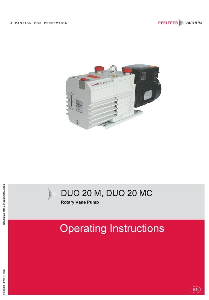
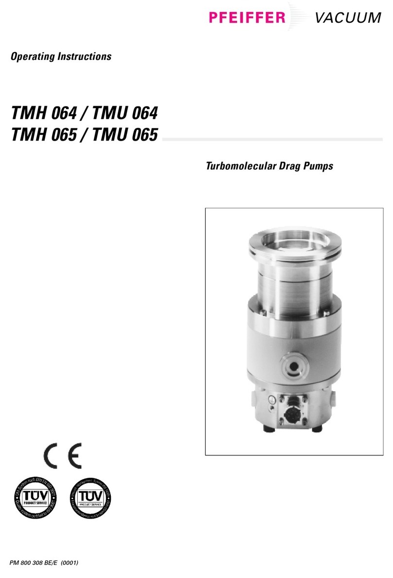
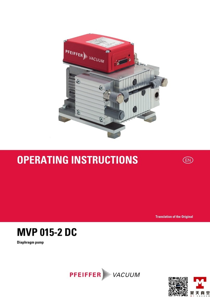
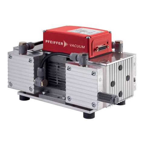
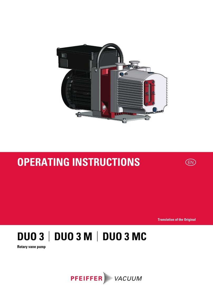
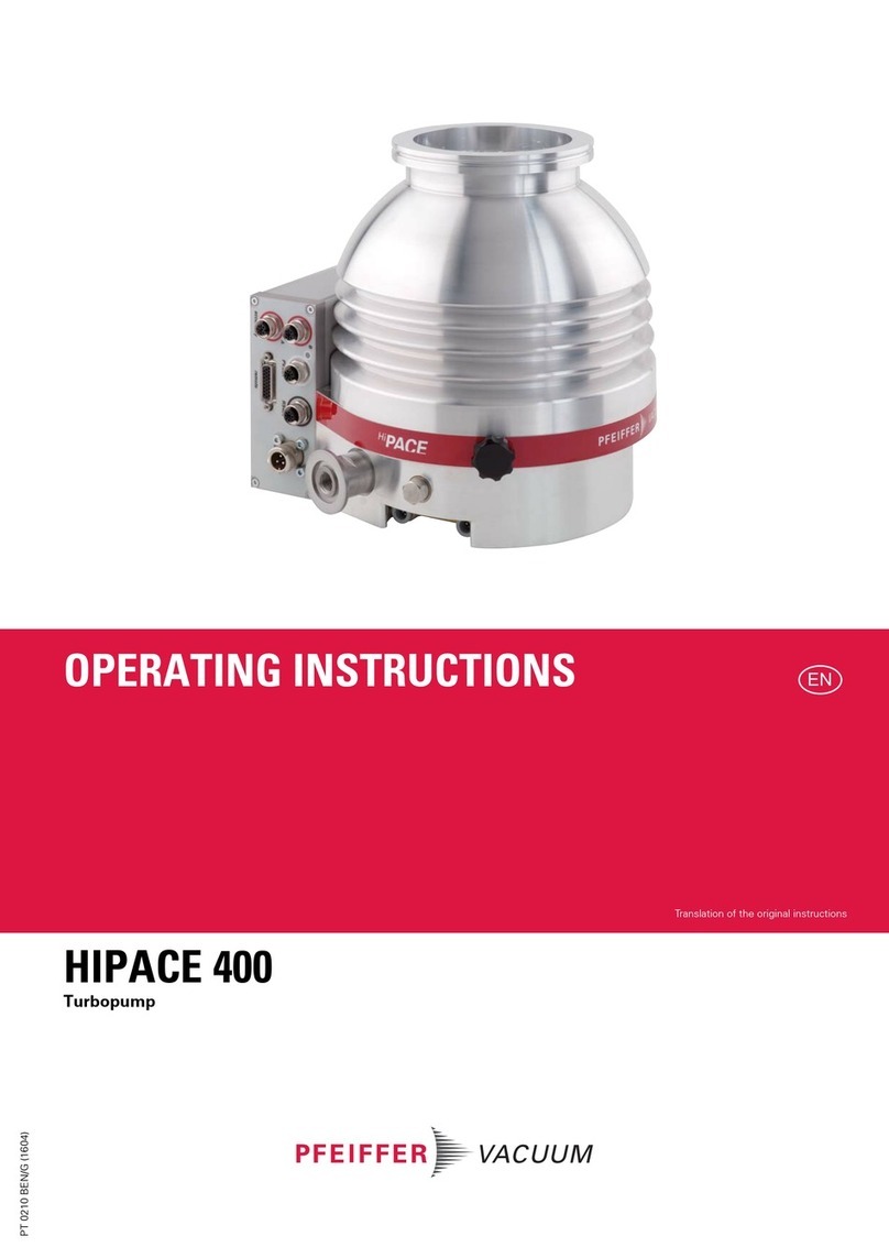
Pfeiffer HIPACE 30 User manual

OPERATING INSTRUCTIONS
EN
Translation of the Original
HIPACE 30
Turbopump

Dear Customer,
Thank you for choosing a Pfeiffer Vacuum product. Your new turbopump is designed to
support you by its performance, its perfect operation and without interfering your individual
application. The name Pfeiffer Vacuum stands for high-quality vacuum technology, a
comprehensive and complete range of top-quality products and first-class service. With this
expertise, we have acquired a multitude of skills contributing to an efficient and secure
implementation of our product.
Knowing that our product must not interfere with your actual work, we are convinced that our
product offers you the solution that supports you in the effective and trouble-free execution of
your individual application.
Please read these operating instructions before putting your product into operation for the
first time. If you have any questions or suggestions, please feel free to contact info@pfeiffer-
vacuum.de.
Further operating instructions from Pfeiffer Vacuum can be found in the Download Center on
our website.
Disclaimer of liability
These operating instructions describe all models and variants of your product. Note that your
product may not be equipped with all features described in this document. Pfeiffer Vacuum
constantly adapts its products to the latest state of the art without prior notice. Please take
into account that online operating instructions can deviate from the printed operating
instructions supplied with your product.
Furthermore, Pfeiffer Vacuum assumes no responsibility or liability for damage resulting from
the use of the product that contradicts its proper use or is explicitly defined as foreseeable
misuse.
Copyright
This document is the intellectual property of Pfeiffer Vacuum and all contents of this
document are protected by copyright. They may not be copied, altered, reproduced or
published without the prior written permission of Pfeiffer Vacuum.
We reserve the right to make changes to the technical data and information in this document.
2/56

Table of contents
1 About this manual 7
1.1 Validity 7
1.1.1 Applicable documents 7
1.1.2 Product variants 7
1.2 Target group 7
1.3 Conventions 7
1.3.1 Instructions in the text 7
1.3.2 Pictographs 8
1.3.3 Stickers on the product 8
1.3.4 Abbreviations 9
1.4 Trademark proof 9
2 Safety 10
2.1 General safety instructions 10
2.2 Safety instructions 10
2.3 Safety precautions 14
2.4 Limits of use of the product 14
2.5 Proper use 15
2.6 Foreseeable improper use 15
2.7 Personnel qualification 15
2.7.1 Ensuring personnel qualification 16
2.7.2 Personnel qualification for maintenance and repair 16
2.7.3 Advanced training with Pfeiffer Vacuum 16
3 Product description 17
3.1 Function 17
3.1.1 Cooling 17
3.1.2 Rotor bearing 17
3.1.3 Drive 17
3.2 Scope of delivery 17
3.3 Identifying the product 18
3.3.1 Product types 18
3.3.2 Product features 18
4 Transportation and Storage 19
4.1 Transport 19
4.2 Storage 19
5 Installation 20
5.1 Preparatory work 20
5.2 Connecting the high vacuum side 20
5.2.1 Requirements for the dimensioning of a counter flange 20
5.2.2 Consider earthquake protection 21
5.2.3 Using a splinter shield or protective screen 22
5.2.4 Using the vibration compensator 22
5.2.5 Mounting orientations 23
5.2.6 Installation of ISO-KF flange 23
5.2.7 Attaching ISO-K flange onto ISO-K 24
5.2.8 Installation of ISO-K flange onto ISO-F 24
5.2.9 Attaching CF flange to CF-F 25
5.3 Connecting the fore-vacuum side 27
5.4 Connecting accessories 28
5.5 Connecting the electrical supply 29
5.5.1 Ground turbopump 29
5.5.2 Establishing the electric connection 29
6 Operation 31
Table of contents
3/56

6.1 Commissioning 31
6.2 Operating modes 32
6.2.1 Operation without operating unit 32
6.2.2 Operation via connection "E74" 32
6.2.3 Operation via multi-function connection "X3" 32
6.2.4 Operation via Pfeiffer Vacuum display and control unit 32
6.2.5 Operation via field bus 32
6.3 Switching on the turbopump 33
6.4 Operation monitoring 33
6.4.1 Operating mode display via LED 33
6.4.2 Temperature monitoring 34
6.5 Switching off and venting 34
6.5.1 Switching off 34
6.5.2 Venting 34
7 Maintenance 36
7.1 General maintenance information 36
7.2 Maintenance intervals and responsibilities 36
7.3 Replacing the operating fluid reservoir 37
7.3.1 Removing the operating fluid reservoir 37
7.3.2 Install operating fluid reservoir 38
7.4 Replace the electronic drive unit 39
7.4.1 Removing electronic drive unit 40
7.4.2 Install the electronic drive unit 40
7.5 Confirming the rotation speed specification 41
8 Decommissioning 42
8.1 Shutting down for longer periods 42
8.2 Recommissioning 42
8.3 Disposing of the vacuum pump 43
9 Malfunctions 44
10 Service solutions from Pfeiffer Vacuum 46
11 Spare parts HiPace 30 48
12 Accessories 49
12.1 Accessory information 49
12.2 Ordering accessories 49
13 Technical data and dimensions 51
13.1 General 51
13.2 Technical data 51
13.3 Dimensions 53
Declaration of conformity 54
Table of contents
4/56

List of tables
Tbl. 1: Abbreviations used in this document 9
Tbl. 2: Permissible ambient conditions 15
Tbl. 3: Product designation of Pfeiffer Vacuum HiPace turbopumps 18
Tbl. 4: Turbopump features 18
Tbl. 5: Requirements for the dimensioning of customer-specific high vacuum con-
nection
21
Tbl. 6: Effect of splinter shield or protective screen on pumping speed 22
Tbl. 7: Factory setting of the electronic drive unit for turbopumps when delivered 31
Tbl. 8: Behavior and meaning of the LEDs on the electronic drive unit 34
Tbl. 9: Factory settings for delayed venting in turbopumps 35
Tbl. 10: Characteristic nominal rotation speeds of the turbopumps 41
Tbl. 11: Troubleshooting turbopumps 45
Tbl. 12: Overview of the spare parts available for the HiPace 30 48
Tbl. 13: HiPace 30 accessories 50
Tbl. 14: Conversion table: Pressure units 51
Tbl. 15: Conversion table: Units for gas throughput 51
Tbl. 16: Technical data for HiPace 30 | 24 V 53
List of tables
5/56

List of figures
Fig. 1: Position of the labels on the product 8
Fig. 2: HiPace 30 design 17
Fig. 3: Example: Safety connections 22
Fig. 4: Recommended alignment when using oil-sealed backing pumps 23
Fig. 5: Flange connection ISO-KF to ISO-KF 23
Fig. 6: Flange connection ISO-K to ISO-F, bracket screws 24
Fig. 7: Flange connection CF-F, hexagon head screw and through hole 26
Fig. 8: Flange connection CF-F, stud screw and tapped hole 26
Fig. 9: Flange connection CF-F, stud screw and through hole 27
Fig. 10: Example of fore-vacuum connection on HiPace 30 27
Fig. 11: Example of accessory connection via adapter TCS 12 28
Fig. 12: Example: Connecting the grounding cable 29
Fig. 13: Connecting the electronic drive unit to a power supply pack 30
Fig. 14: Removing the operating fluid reservoir 38
Fig. 15: Insert capillary rods and install operating fluid reservoir 39
Fig. 16: Removal of electronic drive unit 40
Fig. 17: Assembling the electronic drive unit 41
Fig. 18: Spare parts HiPace 30 48
Fig. 19: Dimensions HiPace 30 | DN 63 ISO-K 53
Fig. 20: Dimensions HiPace 30 | DN 63 CF-F 53
Fig. 21: Dimensions HiPace 30 | DN 40 ISO-KF 53
List of figures
6/56

1 About this manual
IMPORTANT
Read carefully before use.
Keep the manual for future consultation.
1.1 Validity
These operating instructions are for customers of Pfeiffer Vacuum. They describe the function of the
designated product and provide the most important information for safe usage of the product. The de-
scriptions comply with applicable directives. All information provided in these operating instructions refer
to the current development status of the product. The documentation remains valid as long as the cus-
tomer does not modify the product in any way.
1.1.1 Applicable documents
Document Number
Operating instructions, “electronic drive unit" TC 110 standard PT 0204 BN
Operating instructions for "electronic drive unit" TC 110 PB PT 0245 BN
Operating instructions, electronic drive unit TC 110 E74 PT 0301 BN
Operating instructions for "electronic drive unit" TC 110 RS PT 0351 BN
Declaration of conformity Part of this document
You can find these documents in the Pfeiffer Vacuum Download Center.
1.1.2 Product variants
●HiPace 30, DN 63 ISO-K, TC 110
●HiPace 30, DN 63 CF-F, TC 110
●HiPace 30, DN 40 ISO-KF, TC 110
1.2 Target group
These operating instructions are aimed at all persons performing the following activities on the product:
●Transportation
●Setup (Installation)
●Usage and operation
●Decommissioning
●Maintenance and cleaning
●Storage or disposal
The work described in this document is only permitted to be performed by persons with the appropriate
technical qualifications (expert personnel) or who have received the relevant training from Pfeiffer Vac-
uum.
1.3 Conventions
1.3.1 Instructions in the text
Usage instructions in the document follow a general structure that is complete in itself. The required ac-
tion is indicated by an individual step or multi-part action steps.
Individual action step
A horizontal, solid triangle indicates the only step in an action.
►This is an individual action step.
About this manual
7/56

Sequence of multi-part action steps
The numerical list indicates an action with multiple necessary steps.
1. Step 1
2. Step 2
3. ...
1.3.2 Pictographs
Pictographs used in the document indicate useful information.
Note
Tip
1.3.3 Stickers on the product
This section describes all the stickers on the product along with their meaning.
C US
TÜV Rheinland
Oil
S/N
Mod.
HiPace 30
PM P05 280
- - - - - - - -
P/N
n, f
Mass Made in Germany 2019/05
PM 183 900 -T
90000 1/min, 1500 Hz
2.0 kg
D-35614 Asslar
Rating plate
The rating plate of the turbopump is located on the lower part
of the vacuum pump.
Rating plate of the electronic drive unit
The electronic drive unit rating plate is located on the top
Operating instructions note
This sticker indicates that this operating instructions must be
read before performing any tasks.
Protection class
This sticker describes protection class 1 for the product. Its
placement indicates the position for the ground connection.
warranty seal
Closure seal
The product is sealed ex-factory. Damaging or removing a clo-
sure seal results in loss of the warranty.
4
5
3
12
Fig. 1: Position of the labels on the product
1 Operating instructions note 4 Rating plate of the turbopump
2 Electronic drive unit type plate 5 Information regarding ground connection
3 Closure seal
About this manual
8/56

1.3.4 Abbreviations
Abbreviation Meaning in this document
CF Flange: Metal-sealed connector in accordance with ISO 3669
dDiameter value (in mm)
DC Direct current
DCU Display Control Unit.
DN Nominal diameter as size description
fRotation speed value of a vacuum pump (frequency, in rpm or Hz)
HPU Handheld Programming Unit.
HV High vacuum flange, high vacuum side
ISO Flange: Connector in accordance with ISO 1609 and ISO 2861
LED Light emitting diode
PE Earthed conductor (protective earth)
[P:xxx] Electronic drive unit control parameters. Printed in bold as three-digit number in
square brackets. Frequently displayed in conjunction with a short description.
Example: [P:312] software version
S1 S1 switch on power supply pack
TTemperature (in °C)
TC Turbopump electronic drive unit (turbo controller)
TPS Voltage supply (turbo power supply)
VV Fore-vacuum flange, fore-vacuum connection
WAF Width across flats
X3 15-pole D-Sub connecting socket on the turbopump electronic drive unit
Tbl. 1: Abbreviations used in this document
1.4 Trademark proof
●Torx® is a registered trading name of ACUMENT INTELLECTUAL PROPERTIES, LLC.
●Profibus® is a registered trading name of Profibus Nutzerorganisation e.V.
About this manual
9/56

2 Safety
2.1 General safety instructions
This document includes the following 4 risk levels and 1 information level.
DANGER
Imminent danger
Indicates a hazardous situation which, if not avoided, will result in death or serious injury.
►Instructions on avoiding the hazardous situation
WARNING
Possibly imminent danger
Indicates a hazardous situation which, if not avoided, could result in death or serious injury.
►Instructions on avoiding the hazardous situation
CAUTION
Possibly imminent danger
Indicates a hazardous situation which, if not avoided, could result in minor or moderate injury.
►Instructions on avoiding the hazardous situation
NOTICE
Danger of property damage
Notice is used to address practices not related to physical injury.
►Instructions on avoiding property damage
Notes, tips or examples indicate important information on the product or on this document.
2.2 Safety instructions
All safety instructions in this document are based on the results of the risk assessment carried out in
accordance with Machinery Directive 2006/42/EC Annex I and EN ISO 12100 Section 5. Where applica-
ble, all life cycle phases of the product were taken into account.
Risks during transport
WARNING
Danger of serious injury due to falling objects
Due to falling objects there is a risk of injuries to limbs through to broken bones.
►Take particular care and pay special attention when transporting products manually.
►Do not stack the products.
►Wear protective equipment, e.g. safety shoes.
Safety
10/56

Risks during installation
DANGER
Danger to life from electric shock
Power supply packs that are not specified or are not approved will lead to severe injury to death.
►Make sure that the power supply pack meets the requirements for double isolation between
mains input voltage and output voltage, in accordance with IEC 61010 and IEC 60950.
►Make sure that the power supply pack meets the requirements in accordance with IEC 61010
and IEC 60950.
►Where possible, use original power supply packs or only power supply packs that correspond
with the applicable safety regulations.
WARNING
Risk of cuts on moving, sharp-edged parts when reaching into the open high vacuum flange
With the high vacuum flange open, access to sharp-edged parts is possible. A manual rotation of the
rotor increases the danger situation. There is the risk of cuts, up to the separation of body parts (e.g.
fingertips). There is a risk of hair and loose clothing being drawn in. Objects falling in destroy the tur-
bopump during subsequent operation.
►Only remove the original protective covers immediately prior to connecting the high vacuum
flange.
►Do not reach into the high vacuum connection.
►Wear protective gloves during installation.
►Do not start the turbopump with open vacuum connections.
►Always carry out the mechanical installation before electrical connection.
►Prevent access to the high vacuum connection of the turbopump from the operator side (e.g.
open vacuum chamber).
WARNING
Risk of injury caused by the turbopump breaking away with the vibration compensator in the
event of a malfunction
Sudden jamming of the rotor generates high destructive torques in accordance with ISO 27892.
When using a vibration compensator, this will probably lead to the turbopump being sheared off in
use. The energy that this would release could throw the entire turbopump or shattered pieces from its
interior through the surrounding space. Potentially dangerous gases can escape. There is a risk of
very serious injuries, including death, and extensive property damage.
►Take suitable safety precautions on-site for the compensation of the occurring torques.
►Before installing a vibration compensator, you must first of all contact Pfeiffer Vacuum.
WARNING
Danger to life from poisoning where toxic process media leak from damaged connections
Sudden twisting of the turbopump in the event of a fault causes fittings to accelerate. There is the risk
of damaging on-site connections (e.g., fore-vacuum line) and resulting leaks. This results in leakage
of process media. In processes involving toxic media, there is a risk of injury and danger to life due to
poisoning.
►Keep masses connected to the turbopump as low as possible.
►Use flexible lines to connect to the turbopump where necessary.
WARNING
Risk of danger to life through missing mains disconnection device
The vacuum pump and electronic drive unit are not equipped with a mains disconnection device
(mains switch).
►Install a mains disconnection device according to SEMI-S2.
►Install a circuit breaker with an interruption rating of at least 10,000 A.
Safety
11/56

WARNING
Risk of injury due to incorrect installation
Dangerous situations may arise from unsafe or incorrect installation.
►Do not carry out your own conversions or modifications on the unit.
►Ensure the integration into an Emergency Off safety circuit.
WARNING
Danger of cut injuries from unexpected start up.
The use of mating plugs of the electronic drive unit (accessories) enables the automatic run-up of the
vacuum pump as soon the power is turned on. Attaching mating plugs before or during the installa-
tion leads to the movement of parts hence the risk of cut injuries by sharp-edged in the exposed high
vacuum flange.
►Only connect mating plugs after the mechanical installation.
►Only switch on the vacuum pump immediately prior to operation.
Risks during operation
WARNING
Risk of burns on hot surfaces when using additional equipment for heating during operation
The use of additional equipment for heating the vacuum pump or for optimizing the process gener-
ates very high temperatures on surfaces that can be touched. There is a risk of burning.
►If necessary, set up a contact guard.
►If necessary, apply the warning stickers provided for this at the danger points.
►Ensure adequate cooling down before working on the vacuum pump or in its vicinity.
►Wear protective equipment, e.g., gloves.
WARNING
Risk of serious injury in the event of vacuum pump destruction due to over pressure
Gas entry with very high over pressure results in destruction of the vacuum pump. There is a risk of
serious injury due to ejected objects.
►Never exceed the permissible 1500 hPa (absolute) inlet pressure on the suction side or the vent-
ing and sealing gas connection.
►Make sure that high, process-related over pressures cannot directly enter the vacuum pump.
CAUTION
Risk of injuries due to contact with vacuum when venting
While venting the vacuum pump there is a risk of minor injuries due to the direct contact of body parts
with the vacuum, e.g. hematomas.
►Do not fully unscrew the venting screw out of the housing during venting.
►Keep a distance from automatic venting device, such as venting valves.
Risks during maintenance and decommissioning
WARNING
Danger to life from electric shock during maintenance and service work
The device is only completely de-energized when the mains plug has been disconnected and the tur-
bopump is at a standstill. There is a danger to life from electric shock when making contact with live
components.
►Before performing all work, switch off the main switch.
►Wait until the turbopump comes to a standstill (rotation speed =0).
►Remove the mains plug from the device.
►Secure the device against unintentional restarting.
Safety
12/56

WARNING
Risk of cuts on moving, sharp-edged parts when reaching into the open high vacuum connec-
tion
Incorrect handling of the turbopump before maintenance work results in hazardous situations with
risk of injury. There is a risk of cuts from accessing sharp-edged, rotating parts when removing the
turbopump.
►Wait until the turbopump comes to a standstill (rotation speed f=0).
►Switch the turbopump off properly.
►Secure the turbopump against re-start.
►Seal open connections immediately following removal, using the original protective cover.
WARNING
Health hazard through poisoning from toxic contaminated components or devices
Toxic process media result in contamination of devices or parts of them. During maintenance work,
there is a risk to health from contact with these poisonous substances. Illegal disposal of toxic sub-
stances causes environmental damage.
►Take suitable safety precautions and prevent health hazards or environmental pollution by toxic
process media.
►Decontaminate affected parts before carrying out maintenance work.
►Wear protective equipment.
WARNING
Risk of poisoning from contact with harmful substances
The operating fluid reservoir and parts of the turbopump may contain toxic substances from pumped
media.
►Decontaminate affected parts before carrying out maintenance work.
►Prevent health hazards or environmental impacts with adequate safety precautions.
►Observe the operating fluid safety data sheet.
►Dispose of the operating fluid reservoir according to applicable regulations.
Risks in the event of malfunctions
WARNING
Danger to life from the turbopump breaking away in the event of a fault
Sudden jamming of the rotor generates high destructive torques in accordance with ISO 27892. If the
turbopump is not properly secured, it can shear off. The energy that this would release could throw
the entire turbopump or shattered pieces from its interior through the surrounding space. Potentially
dangerous gases can escape. There is a risk of very serious injuries, including death, and extensive
property damage.
►Follow the installation instructions for this turbopump.
►Observe the requirements regarding stability and design of the counter flange.
►Use only original accessories or fixing material approved by Pfeiffer Vacuum for the installation.
WARNING
Risk of injury caused by the turbopump breaking away with the vibration compensator in the
event of a malfunction
Sudden jamming of the rotor generates high destructive torques in accordance with ISO 27892.
When using a vibration compensator, this will probably lead to the turbopump being sheared off in
use. The energy that this would release could throw the entire turbopump or shattered pieces from its
interior through the surrounding space. Potentially dangerous gases can escape. There is a risk of
very serious injuries, including death, and extensive property damage.
►Take suitable safety precautions on-site for the compensation of the occurring torques.
►Before installing a vibration compensator, you must first of all contact Pfeiffer Vacuum.
Safety
13/56

WARNING
Danger to life from poisoning where toxic process media leak from damaged connections
Sudden twisting of the turbopump in the event of a fault causes fittings to accelerate. There is the risk
of damaging on-site connections (e.g., fore-vacuum line) and resulting leaks. This results in leakage
of process media. In processes involving toxic media, there is a risk of injury and danger to life due to
poisoning.
►Keep masses connected to the turbopump as low as possible.
►Use flexible lines to connect to the turbopump where necessary.
2.3 Safety precautions
Duty to provide information on potential dangers
The product holder or user is obliged to make all operating personnel aware of dangers
posed by this product.
Every person who is involved in the installation, operation or maintenance of the product
must read, understand and adhere to the safety-related parts of this document.
Infringement of conformity due to modifications to the product
The Declaration of Conformity from the manufacturer is no longer valid if the operator
changes the original product or installs additional equipment.
●Following the installation into a system, the operator is required to check and re-evalu-
ate the conformity of the overall system in the context of the relevant European Direc-
tives, before commissioning that system.
General safety precautions when handling the product
►Observe all applicable safety and accident prevention regulations.
►Check that all safety measures are observed at regular intervals.
►Do not expose body parts to the vacuum.
►Always ensure a secure connection to the earthed conductor (PE).
►Never disconnect plug connections during operation.
►Observe the above shutdown procedures.
►Before working on the high vacuum connection, wait until the rotor has stopped completely (rota-
tion speed f = 0).
►Never put the device into operation with the high vacuum connection open.
►Keep lines and cables away from hot surfaces (> 70°C).
►Never fill or operate the unit with cleaning agents or cleaning agent residues.
►Do not carry out your own conversions or modifications on the unit.
►Observe the unit protection class prior to installation or operation in other environments.
2.4 Limits of use of the product
Installation location weatherproof (internal space)
Air pressure 750 hPa to 1060 hPa
Installation altitude max. 5000 m
Rel. air humidity max. 80%, at T <31°C,
up to max. 50% at T <40°C
Protection class III
Excess voltage category II
Permissible protection degree IP54
Degree of contamination 2
Ambient temperature 5 °C to 30 °C with convection cooling without gas through-
put
5 °C to 35°C with air cooling
Safety
14/56

Permissible surrounding magnetic field 3 mT
Maximum irradiated thermal output 1.2 W
Tbl. 2: Permissible ambient conditions
Notes on ambient conditions
The specified permissible ambient temperatures apply to operation of the turbopump at
maximum permissible backing pressure or at maximum gas throughput, depending on the
cooling type. The turbopump is intrinsically safe thanks to redundant temperature monitor-
ing.
●The reduction in backing pressure or gas throughput permits operation of the turbo-
pump at higher ambient temperatures.
●If the maximum permissible operating temperature of the turbopump is exceeded, the
electronic drive unit first reduces the drive output and then switches it off where neces-
sary.
2.5 Proper use
►Use the turbopump only for generating vacuum.
►Use the turbopump only in combination with a suitable backing pump that can deliver up to the
required maximum fore-vacuum pressure.
►Use the turbopump only in closed indoor areas.
►Use the turbopump only for the evacuation of dry and inert gases.
2.6 Foreseeable improper use
Improper use of the product invalidates all warranty and liability claims. Any use that is counter to the
purpose of the product, whether intentional or unintentional, is regarded as misuse, in particular:
●Establishing the voltage supply without correct installation
●Installation with non-specified fastening material
●Pumping explosive media
●Pumping of corrosive media
●Pumping of condensing vapors
●Pumping of fluids
●Pumping of dust
●Operation with impermissible high gas throughput
●Operation with impermissible high fore-vacuum pressure
●Operation with excessively high irradiated heat output
●Operation in impermissible high magnetic fields
●Operation in an incorrect gas mode
●Venting with impermissible high venting rates
●Use for pressure generation
●Use in areas with ionizing radiation
●Operation in explosion-hazard areas
●Use in systems in which sporadic loads and vibrations or periodic forces act on the device
●The causing of hazardous operating conditions by a presetting on the electronic drive unit that is
contrary to the process
●Use of accessories or spare parts that are not listed in these instructions
2.7 Personnel qualification
The work described in this document may only be carried out by persons who have appropriate profes-
sional qualifications and the necessary experience or who have completed the necessary training as
provided by Pfeiffer Vacuum.
Training people
1. Train the technical personnel on the product.
2. Only let personnel to be trained work with and on the product when under the supervision of
trained personnel.
Safety
15/56

3. Only allow trained technical personnel to work with the product.
4. Before starting work, make sure that the commissioned personnel have read and understood
these operating instructions and all applicable documents, in particular the safety, maintenance
and repair information.
2.7.1 Ensuring personnel qualification
Specialist for mechanical work
Only a trained specialist may carry out mechanical work. Within the meaning of this document, special-
ists are people responsible for construction, mechanical installation, troubleshooting and maintenance
of the product, and who have the following qualifications:
●Qualification in the mechanical field in accordance with nationally applicable regulations
●Knowledge of this documentation
Specialist for electrotechnical work
Only a trained electrician may carry out electrical engineering work. Within the meaning of this docu-
ment, electricians are people responsible for electrical installation, commissioning, troubleshooting, and
maintenance of the product, and who have the following qualifications:
●Qualification in the electrical engineering field in accordance with nationally applicable regulations
●Knowledge of this documentation
In addition, these individuals must be familiar with applicable safety regulations and laws, as well as the
other standards, guidelines, and laws referred to in this documentation. The above individuals must
have an explicitly granted operational authorization to commission, program, configure, mark, and earth
devices, systems, and circuits in accordance with safety technology standards.
Trained individuals
Only adequately trained individuals may carry out all works in other transport, storage, operation and
disposal fields. Such training must ensure that individuals are capable of carrying out the required activi-
ties and work steps safely and properly.
2.7.2 Personnel qualification for maintenance and repair
Advanced training courses
Pfeiffer Vacuum offers advanced training courses to maintenance levels 2 and 3.
Adequately trained individuals are:
●Maintenance level 1
─Customer (trained specialist)
●Maintenance level 2
─Customer with technical education
─Pfeiffer Vacuum service technician
●Maintenance level 3
─Customer with Pfeiffer Vacuum service training
─Pfeiffer Vacuum service technician
2.7.3 Advanced training with Pfeiffer Vacuum
For optimal and trouble-free use of this product, Pfeiffer Vacuum offers a comprehensive range of
courses and technical trainings.
For more information, please contact Pfeiffer Vacuum technical training.
Safety
16/56

3 Product description
3.1 Function
The turbopump forms a compact unit with the electronic drive unit. Pfeiffer Vacuum power supply packs
provide the voltage supply.
45 6 7
8
3
1
9
2
10
11
12
13
1415
Fig. 2: HiPace 30 design
1 Protective cover for the high vacuum connec-
tion
9 Fore-vacuum connection, DN 16 ISO-KF
2 Pump housing, aluminum 10 Electronic drive unit TC 110
3 Venting screw 11 Protective cover for the fore-vacuum connec-
tion
4 Sealing gas connection 12 Rubber-metal bumper
5 Ground terminal 13 Pump base
6 Pump housing, stainless steel 14 Multifunction connection "X3"
7 Turbo rotor 15 LED operating mode display
8 High vacuum connection, DN 63 CF-F
3.1.1 Cooling
●Convection cooling
●Air cooling (optional)
The electronic drive unit automatically regulates the drive power downward at excess temperatures.
3.1.2 Rotor bearing
Hybrid-bearing turbopump
●High vacuum side: wear-free permanent magnetic bearing
●Fore-vacuum side: ball bearing with ceramic balls
Permanent lubrication of the rotor bearing on the fore-vacuum side is ensured by an operating fluid res-
ervoir.
3.1.3 Drive
●TC 110 electronic drive unit
3.2 Scope of delivery
●Turbopump with electronic drive unit
●Protective cover for the high vacuum connection
●Protective cover for the fore-vacuum connection
●Operating instructions
Product description
17/56

3.3 Identifying the product
►To ensure clear identification of the product when communicating with Pfeiffer Vacuum, always
keep all of the information on the rating plate to hand.
►Learn about certifications through test seals on the product or at www.certipedia.com with compa-
ny ID no. 000021320.
3.3.1 Product types
The product designation of Pfeiffer Vacuum turbopumps from the HiPace series is composed of the
family name, the size (which is based on the pumping speed of the vacuum pump) and, if required, an
additional feature description.
Family Size/model Property, attribute, feature
HiPace 10 to 2800 none = Standard version
mini = Compact version
U = Overhead version
C = Corrosive gas version
P = Process
M = Active magnetic bearing
T = Temperature management
Plus = Low vibration, low magnetic field
E = High efficiency
H = High compression
I = Ion implantation
Tbl. 3: Product designation of Pfeiffer Vacuum HiPace turbopumps
3.3.2 Product features
Feature Version
HV flange DN 63 ISO-K DN 63 CF-F DN 40 ISO-KF
Flange material Aluminium Stainless steel Aluminium
Tbl. 4: Turbopump features
Product description
18/56

4 Transportation and Storage
4.1 Transport
WARNING
Danger of serious injury due to falling objects
Due to falling objects there is a risk of injuries to limbs through to broken bones.
►Take particular care and pay special attention when transporting products manually.
►Do not stack the products.
►Wear protective equipment, e.g. safety shoes.
We recommend
Pfeiffer Vacuum recommends keeping the transport packaging and original protective cov-
er.
Instructions for safe transport
►Transport the turbopump only within the permissible temperature limits.
►Observe weight specified on the rating plate.
►Where possible, always transport or ship the turbopump in its original packaging.
►Always carry the turbopump with both hands.
►Remove the protective cover only immediately prior to installation.
4.2 Storage
We recommend
Pfeiffer Vacuum recommends storing the products in their original transport packaging.
Storing the turbopump
1. Seal all flange openings with the original protective caps.
2. Seal all other connections (e.g. venting connection) with the corresponding original parts.
3. Store the turbopump only indoors within the permissible temperature limits.
4. In rooms with humid or aggressive atmospheres: Hermetically seal the turbopump together with a
drying agent in a plastic bag.
Transportation and Storage
19/56

5 Installation
The installation of the turbopump and its fastening is of outstanding importance. The rotor of the turbo-
pump revolves at very high speed. In practice it is not possible to exclude the risk of the rotor touching
the stator (e.g. due to the penetration of foreign bodies into the high vacuum connection). The kinetic
energy released acts on the housing and on the anchoring of the turbopump within fractions of a sec-
ond.
Comprehensive tests and calculations conforming to ISO 27892 confirm the safety of the turbopump
both against crashes (destruction of the rotor blade) and against bursting (breakage of the rotor shaft).
The experimental and theoretical results are expressed in safety measures and recommendations for
the correct and safe fastening of the turbopump.
5.1 Preparatory work
WARNING
Risk of cuts on moving, sharp-edged parts when reaching into the open high vacuum flange
With the high vacuum flange open, access to sharp-edged parts is possible. A manual rotation of the
rotor increases the danger situation. There is the risk of cuts, up to the separation of body parts (e.g.
fingertips). There is a risk of hair and loose clothing being drawn in. Objects falling in destroy the tur-
bopump during subsequent operation.
►Only remove the original protective covers immediately prior to connecting the high vacuum
flange.
►Do not reach into the high vacuum connection.
►Wear protective gloves during installation.
►Do not start the turbopump with open vacuum connections.
►Always carry out the mechanical installation before electrical connection.
►Prevent access to the high vacuum connection of the turbopump from the operator side (e.g.
open vacuum chamber).
General notes for the installation of vacuum components
►Choose an installation location that permits access to the product and to supply lines at all times.
►Observe the ambient conditions given for the area of use.
►Provide the highest possible level of cleanliness during assembly.
►Ensure that flange components during installation are grease-free, dust-free and dry.
Select the installation location
1. Observe the instructions for transport to the installation location.
2. Make sure that there are sufficient cooling options for the turbopump.
3. Install suitable shielding if the surrounding magnetic fields exceed the permissible levels.
4. Install suitable shielding so that the irradiated thermal output does not exceed the permissible val-
ues when high temperatures occur due to the process.
5. Observe the permissible temperatures for the vacuum connection.
5.2 Connecting the high vacuum side
5.2.1 Requirements for the dimensioning of a counter flange
NOTICE
Risk of damage due to incorrect counter flange design
Unevenness on the operator-side counter flange results in stresses in the vacuum pump housing,
even when properly attached. This can produce leakage or negative changes in running characteris-
tics.
►Adhere to the shape tolerances for the counter flange.
►Observe the maximum flatness deviations over the entire surface.
Installation
20/56
Table of contents
Other Pfeiffer Water Pump manuals

Pfeiffer
Pfeiffer TMH 065 User manual

Pfeiffer
Pfeiffer HiPace 400 User manual

Pfeiffer
Pfeiffer DUO 3 User manual

Pfeiffer
Pfeiffer MVP 010-3 DC User manual

Pfeiffer
Pfeiffer MVP 015-4 DC User manual

Pfeiffer
Pfeiffer DuoLine DUO 20 M User manual

Pfeiffer
Pfeiffer TPU 062 User manual

Pfeiffer
Pfeiffer HiPace 300 User manual

Pfeiffer
Pfeiffer HISCROLL 6 User manual

Pfeiffer
Pfeiffer DUO 20 M User manual

Popular Water Pump manuals by other brands

GORMAN-RUPP PUMPS
GORMAN-RUPP PUMPS PRIME-AIRE PA6D manual

PFT
PFT RITMO XL FU 230 operating instructions

WAGNER
WAGNER Unica 4-270 Translation of the original operating manual

Calpeda
Calpeda META quick start

EINHELL
EINHELL RG-AW 1139 operating instructions

SAER Elettropompe
SAER Elettropompe PMK Series manual