manuals.online logo
Brands
  1. Home
  2. •
  3. Brands
  4. •
  5. PFlow Industries
  6. •
  7. Lifting System
  8. •
  9. PFlow Industries D Series User manual

PFlow Industries D Series User manual

15702-0001 | Rev I | 2019-07-15 | Printed in the U.S.A.
D Series | Hydraulic VRC
Installation Manual
Customer:
Job Number:
Important:
Read this entire manual.
Important safety information
is included.
Before starting the installation,
verify the job site dimensions and the
dimensions of the delivered materials
against the PFlow Industries, Inc.
General Arrangement (GA) drawing.
The illustrations depicted in this manual
are not to scale or detail. The illustrations
are for reference only.
www.pflow.com
P 414 352 9000
F 414 352 9002
6720 N. Teutonia Ave.
Milwaukee, WI 53209
72&_ '6HULHV__5HY,__HPDLOSVG#SÁRZFRP
Table of Contents
www.pflow.com
P 414 352 9000
F 414 352 9002
6720 N. Teutonia Ave.
Milwaukee, WI 53209
Description Section | Page
1. Contact Information 15705-0011 1 | 1
2. General Information 15710-0004 2 | 1
Introduction 2 | 1
General Overview 2 | 1
Code Requirements 2 | 1
Parts 2 | 1
Service 2 | 1
Feedback 2 | 1
3. Warranty Information 15710-0014 3 | 1
Parts and Labor 3 | 1
'HÀQLWLRQV 3 | 1
Warranty 3 | 1
Exclusions 3 | 1
Obligation 3 | 1
Liability 3 | 2
Warranty Procedures 3 | 2
Pre-Authorization 3 | 2
Invoices 3 | 2
4. Important Safety Information 15702-0004 4 | 1
Read the Entire Manual 4 | 1
Intended Purpose 4 | 1
Safety Alert Symbols 4 | 1
Danger Statements 4 | 2
Warning Statements 4 | 2
Hydraulic Safety Precautions 4 | 4
Caution Statements 4 | 5
Electrical Safety Precautions 4 | 6
De-energize the Circuit 4 | 6
Electrical Safety Precautions 4 | 7
Working on Energized Circuits 4 | 7
Notes for the Installation Electrician 4 | 7
Entrance Below a Raised Carriage Deck 15709-0083 4 | 9
5. Glossary 15710-0018 5 | 1
Unique Descriptions and Names 5 | 1
Gate Types 5 | 8
Identifying Call Outs 5 |9
Table of Contents
'6HULHV__5HY,__HPDLOSVG#SÁRZFRP 72&_
www.pflow.com
P 414 352 9000
F 414 352 9002
6720 N. Teutonia Ave.
Milwaukee, WI 53209
Description Section | Page
6. Equipment Arrival and Unpacking 15710-0006 6 | 1
Arrival 6 | 1
Inspection 6 | 1
Transportation Damage and Claims 6 | 1
Shipping Photograph Examples 6 | 2
Shipping Packet 6 | 3
Return Materials Authorization (RMA) 6 | 3
Warranty Work 6 | 3
Recommended Tools 6 | 4
7. Pre-Installation Responsibilities 15710-0008 7 | 1
End User Responsibilities 7 | 1
End User and/or Mechanical and/or Electrical
Installer Responsibilities
7 | 1
Mechanical Installer Responsibilities 7 | 2
Electrical Installer Responsibilities 7 | 2
8. Job Site General Arrangement (GA) Review 15710-0011 8 | 1
9. Frequently Asked Questions 15710-0011 9 | 1
10. Sequence of Installation 10 | 1
11. Placement 15702-0011 11 | 1
Verify Job Site Dimensions and Carriage Orientation 11 | 1
Mark Alignment 11 | 1
Position the Carriage 11 | 2
12. Backframe Setup 15702-0005 12 | 1
Purpose 12 | 1
Remove the Back Panel 12 | 1
Review the GA Drawing for Backframe Placement 12 | 1
Spliced Backframe Guidelines 12 | 2
Assemble the Spliced Backframe 12 | 2
Align the Spliced Backframe 12 | 3
Tack Weld the Spliced Backframe 12 | 4
Spliced Backframe Finish Welding Details 12 | 4
Insert the Wheelblocks 12 | 5
Raise and Secure the Backframe 12 | 5
Attach the Wheelblocks 12 | 6
Review the Backframe for Plumb 12 | 7
Brace the Backframe 12 | 8
Install the Hydraulic Cylinder 12 | 9
72&_ '6HULHV__5HY,__HPDLOSVG#SÁRZFRP
Table of Contents
www.pflow.com
P 414 352 9000
F 414 352 9002
6720 N. Teutonia Ave.
Milwaukee, WI 53209
Description Section | Page
13. Bracing 15702-0013 13 | 1
Required Anchoring and Bracing Guidelines 13 | 1
Side-to-Side and Front-to-Back Bracing 13 | 2
Bracing Supplies 13 | 2
Anchoring Guidelines 13 | 3
Bracing Guidelines 13 | 4
Table of Contents
'6HULHV__5HY,__HPDLOSVG#SÁRZFRP 72&_
www.pflow.com
P 414 352 9000
F 414 352 9002
6720 N. Teutonia Ave.
Milwaukee, WI 53209
Description Section | Page
16. Gate Installation 15709-0005 16 | 1
Identify Components 16 | 1
Sliding Gate 16 | 2
Assemble the Sliding Gate 16 | 2
Install the Gate Post Extensions 16 | 3
Raise and Secure the Sliding Gate 16 | 4
Anchor the Gate Post Base Plates 16 | 4
Plumb and Square the Gate 16 | 4
Install Support Braces 16 | 4
Verify Gate Operation 16 | 4
Install the Gate Interlock 16 | 5
Verify the Gate Interlock Operation 16 | 5
Adjust the Interlock Keeper Assembly Magnet 16 | 5
Bi-Parting Swing Gate 16 | 6
Assemble the Bi-Parting Swing Gate 16 | 6
Install the Gate Post Extensions 16 | 7
Raise and Secure the Gate Assembly 16 | 8
Anchor the Gate Post Base Plates 16 | 8
Plumb and Square the Gate 16 | 8
Install Support Braces 16 | 8
Verify the Gate Panel Swing 16 | 8
Install the Gate Interlock 16 | 9
Verify the Gate Interlock Operation 16 | 9
Adjust the Interlock Keeper Assembly Magnet 16 | 9
Swing Gate 16 | 10
Assemble the Swing Gate 16 | 10
Install the Gate Post Extensions 16 | 11
Raise and Secure the Swing Gate Assembly 16 | 12
Anchor the Gate Post Base Plates 16 | 12
Plumb and Square the Gate 16 | 12
Install Support Braces 16 | 12
Verify the Gate Panel Swing 16 | 12
Install the Gate Interlock 16 | 13
Verify the Gate Interlock Operation 16 | 13
Adjust the Interlock Keeper Assembly Magnet 16 | 13
72&_ '6HULHV__5HY,__HPDLOSVG#SÁRZFRP
Table of Contents
www.pflow.com
P 414 352 9000
F 414 352 9002
6720 N. Teutonia Ave.
Milwaukee, WI 53209
Description Section | Page
16. Gate Installation (continued)
Single Vertical Acting (SVA) Gate 16 | 14
Establish Placement 16 | 14
Prepare the Chains in the Gate Posts 16 | 15
Begin Horizontal Assembly 16 | 16
Install the Header 16 | 16
Install the Chains 16 | 17
Assemble the Gate Panel 16 | 18
Attach the Gate Panel to the Gate Chains 16 | 18
Raise and Secure the Gate 16 | 19
Align the Gate Assembly 16 | 19
Anchor the Gate Post Base Plates 16 | 19
Plumb and Square the Gate 16 | 20
Install Support Braces 16 | 20
Adjust the Gate Panel 16 | 21
Install the Gate Panel Interlock 16 | 22
Verify the Gate Operation 16 | 22
Begin Vertical Assembly 16 | 23
Establish Placement 16 | 23
Prepare the Chains in the Gate Posts 16 | 23
Raise and Secure the Gate Posts 16 | 23
Install the Header 16 | 24
Install the Chains 16 | 24
Assemble the Gate Panel 16 | 25
Attach the Gate Panel to the Gate Chains 16 | 26
Install Support Braces 16 | 26
Adjust the Gate Panel 16 | 27
Install the Gate Interlock 16 | 28
Verify the Gate Operation 16 | 28
Table of Contents
'6HULHV__5HY,__HPDLOSVG#SÁRZFRP 72&_
www.pflow.com
P 414 352 9000
F 414 352 9002
6720 N. Teutonia Ave.
Milwaukee, WI 53209
Description Section | Page
16. Gate Installation (continued)
Carriage Mounted Single Vertical Acting (SVA) Gate 16 | 29
Establish Placement 16 | 29
Prepare the Chains in the Gate Posts 16 | 30
Begin Horizontal Assembly 16 | 31
Install the Header 16 | 31
Install the Chains 16 | 32
Assemble the Gate Panel 16 | 33
Attach the Gate Panel to the Gate Chains 16 | 33
Raise and Secure the Gate 16 | 34
Align the Gate Assembly 16 | 34
Plumb and Square the Gate 16 | 35
Weld the Gate Posts 16 | 35
Install Support Braces 16 | 35
Attach the Bumpers 16 | 36
Adjust the Gate Panel 16 | 36
Install the Gate Limit Switch and Stationary
Junction Boxes
16 | 37
Verify the Gate Operation 16 | 37
Begin Vertical Assembly 16 | 38
Establish Placement 16 | 38
Prepare the Chains in the Gate Posts 16 | 38
Raise and Secure the Gate Posts 16 | 38
Install the Header 16 | 39
Install the Chains 16 | 39
Assemble the Gate Panel 16 | 41
Attach the Gate Panel to the Gate Chains 16 | 41
Plumb and Square the Gate 16 | 42
Weld the Gate Posts 16 | 42
Install Support Braces 16 | 42
Attach the Bumpers 16 | 43
Adjust the Gate Panel 16 | 43
Install the Gate Limit Switch and Stationary
Junction Boxes
16 | 44
Verify the Gate Operation 16 | 44
72&_ '6HULHV__5HY,__HPDLOSVG#SÁRZFRP
Table of Contents
www.pflow.com
P 414 352 9000
F 414 352 9002
6720 N. Teutonia Ave.
Milwaukee, WI 53209
Description Section | Page
17. Gate Cable Interlock 15709-0029 17 | 1
Important Safety Information 17 | 1
Purpose 17 | 2
General Description 17 | 4
Carriage Cam 17 | 4
Column Mounted Roller Assembly 17 | 4
Control Cable 17 | 4
Gate Cable Interlock Assembly 17 | 4
Peelle Terms 17 | 5
Important Safety Information 17 | 6
Straddle Placement 17 | 7
Cantilever Placement 17 | 7
Adjust the Interlock Assembly 17 | 8
Adjust the Cam and Cable 17 | 8
Position the Roller Arm on the VRC Column 17 | 9
Wire the Electrical Switches 17 | 11
18. Enclosure Panels 15709-0038 18 | 1
Full Height Enclosures 18 | 1
Inventory Enclosure Panels 18 | 2
Assemble and Install Enclosure Panels 18 | 2
19. Signage Locations 15709-0035 19 | 1
20. Landing Platform or Ramp 15709-0004 20 | 1
Install the Gate Post Extensions 20 | 1
Install the Landing Platform 20 | 1
Install the Ramp 20 | 1
Table of Contents
'6HULHV__5HY,__HPDLOSVG#SÁRZFRP 72&_
www.pflow.com
P 414 352 9000
F 414 352 9002
6720 N. Teutonia Ave.
Milwaukee, WI 53209
Description Section | Page
21. Hydraulic Installation and
Start-up Procedures
15702-0010 21 | 1
Hydraulic Safety Precautions 21 | 1
General Hydraulic Information 21 | 2
General Hydraulic Precautions 21 | 2
Install the Hydraulic Pump 21 | 3
Review the GA Drawing for Placement 21 | 3
Placement Considerations 21 | 3
Clean the Fittings and Hoses 21 | 4
Attach the Fittings and Hose to the Cylinder 21 | 4
Attach the Fitting and Hose to the Hydraulic
Pump
21 | 5
Thread Sizes 21 | 5
Install the Breather Cap 21 | 6
Start-up Procedures 21 | 7
&RQÀUP(VWRS6DIHW\2SHUDWLRQ 21 | 7
&RQÀUP0RWRU5RWDWLRQ 21 | 7
Make Sure There are No Leaks 21 | 7
&RQÀUPWKDWWKH3XPS0RWRU6KXWV2II 21 | 8
Adjust the Pressure Relief Valve (if needed) 21 | 8
Adjust the Pressure Switch (if needed) 21 | 8
&RQÀUP&DUULDJH6WRSVDUH/HYHOZLWKWKH
Floor
21 | 9
&RQÀUP95&7UDYHO6SHHGV 21 | 9
Adjust the Flow Control Valve (if needed) 21 | 9
&RQÀUP*DWH6DIHW\2SHUDWLRQ 21 | 9
22. Adjust Motor Overload Sensor (MOL) 15702-0022 22 | 1
The Purpose of the Motor Overload Sensor
(MOL)
22 | 1
Locate the Full Load Amperage (F.L.A.) Value
Test and Calibrate the MOL 22 | 1
23. Installation Completion Checklist 15702-0023 23 | 1
24. Installation Questionnaire 15708-1500 24 | 1
$FFHSWDQFH&HUWLÀFDWLRQ95& 15710-0017-VRC 25 | 1
TOC | 10 '6HULHV__5HY,__HPDLOSVG#SÁRZFRP
Table of Contents
www.pflow.com
P 414 352 9000
F 414 352 9002
6720 N. Teutonia Ave.
Milwaukee, WI 53209
Options
Description Document # Revision
Bill of Material Sheets
Document #
Customer Information
Customer Name Job Number
Table of Contents
'6HULHV__5HY,__HPDLOSVG#SÁRZFRP 72&_
www.pflow.com
P 414 352 9000
F 414 352 9002
6720 N. Teutonia Ave.
Milwaukee, WI 53209
Customer Information
Customer Name Job Number
Job Drawings
Description Document # Revision
TOC | 12 '6HULHV__5HY,__HPDLOSVG#SÁRZFRP
Table of Contents
www.pflow.com
P 414 352 9000
F 414 352 9002
6720 N. Teutonia Ave.
Milwaukee, WI 53209
15705-0011 | Rev H | 2018-04-01 | e-mail psd@pow.com Section 1 | 1
Section 1 | Contact Information
www.pflow.com
P 414 352 9000
F 414 352 9002
6720 N. Teutonia Ave.
Milwaukee, WI 53209
PFlow Industries, Inc.
6720 N. Teutonia Avenue
Milwaukee, Wisconsin 53209
Oce
Phone: 414-352-9000
Fax: 414-352-9002
Product Support Department
e-mail: psd@pow.com
Sales
e-mail: sales@pow.com
For a list of contact personnel visit the PFlow Industries, Inc. website at:
http://www.pow.com/contact-us/
PFlow Industries, Inc. reserves the right to make changes or improvements to
the standard model line at any time. PFlow Industries, Inc. reserves the right
to make changes to subsequent editions of the manual without prior notice to
holders of this edition.
© Copyright April 2018 by PFlow Industries, Inc.
All rights reserved.
No part of this manual may be reproduced or used in any form without
expressed written permission from PFlow Industries, Inc.
This publication may be photocopied by the original purchaser of the
VRC. Any other type of reproduction is prohibited without express written
permission from PFlow Industries, Inc.
All trademarks referenced in this manual are the property of their
respectiveowners.
Mechanical or electrical modications performed on the VRC not approved
by PFlow Industries, Inc. may void any warranty and/or service agreements.
Please contact the PFlow Product Support Department for assistance with
service modications.
Training is available upon request from the Product Support Department.
Half-Day, Full-Day, and Two-Day sessions are customized to t specic needs -
either for a single VRC type or for the entire product line.
On-site supervision services are available from the Product Support
Department. Contact our Field Operations Manager for more details.
This manual is written in American English.
Documentation
Copyright Notice
Trademarks
Training
On-site Supervision
Source Language
System
Modications/
Disclaimer
Section 1 | 2 15705-0011 | Rev H | 2018-04-01 | e-mail psd@pow.com
Section 1 | Contact Information
www.pflow.com
P 414 352 9000
F 414 352 9002
6720 N. Teutonia Ave.
Milwaukee, WI 53209
15710-0004 | Rev C | 2018-04-01 | e-mail psd@pow.com Section 2 | 1
Section 2 | General Information
www.pflow.com
P 414 352 9000
F 414 352 9002
6720 N. Teutonia Ave.
Milwaukee, WI 53209
This manual provides information about the PFlow Industries, Inc. custom designed
Vertical Reciprocating Conveyor (VRC). As the nations’ leading manufacturer of
vertical material handling equipment, PFlow Industries, Inc. is condent that this
new VRC will provide many years of reliable service.
The VRC provides a safe and simple means of moving material from one level to
another. The simplicity of design and few moving components ensure a trouble-free,
long life, with low maintenance and little downtime.
This VRC is designed for the movement of materials only, up to the VRC’s rated capacity,
from one level to the next. Do not allow anyone to ride on the VRC. VRCs are not
elevators, and are specically excluded within the scope of the ASMEA17.1 Safety
Code for Elevators and Escalators. VRCs are included in ASMEB20.1 Safety Standard
for Conveyors and Related Equipment, which is incorporated by reference into OSHA
29 CFR 1910. A copy of the ASME B20.1 standard can be purchased at
www.asme.org and other sources. PFlow Industries, Inc. recommends that this
standard be referenced for appropriate installation, maintenance, inspection,
and operation in relation to hazards. All electrical designs and components are in
accordance with National Electric Code (NEC) requirements. Local codes may
require initial inspection of the installation and periodic inspection and testing of the
unit. Contact PFlow Industries, Inc. for more information in the event an inspection
is required.
The information and illustrations in this manual are intended only as an aid to understanding
the VRCs general installation. The information and illustrations do not cover every possible
contingency or circumstance regarding nonstandard options or siteconditions.
If there is a problem, call PFlow Industries, Inc. at (414) 352-9000, during normal
business hours, 8:30 a.m. to 5:00 p.m. central standard time, Monday through
Friday. Outside of those hours, see the PFlow Industries, Inc. Contact Information
page for additional information. Use the model number and serial number or the
PFlow Industries, Inc. General Arrangement (GA) drawing number for the li in
allcorrespondence.
Equipment damage resulting from modication in any manner from the original
model, including the substitution of parts other than factory authorized parts, will
void thewarranty. Furthermore, PFlow Industries, Inc. will not be liable for any loss,
injury, or damage to persons or property, nor for direct, indirect, or consequential
damage of any kind resulting from modied or substitution of parts other than
factory authorized parts of said material or equipment.
PFlow Industries, Inc. maintains a complete stock of, or has access to, all replacement
components. Detailed records of all equipment sold are kept. If a component is
damaged in shipment, is defective or missing, contact PFlow Industries immediately.
The PFlow Industries, Inc. Product Support Department will assist maintenance
and service personnel with any questions or problems regarding the equipment
orinstallation.
Your feedback is important. Please help PFlow Industries, Inc. understand if the
equipment has met your expectations. Please complete the questionnaire in this
manual. The questionnaire will help us address any comments and/or concerns.
Introduction
General
Overview
Code
Requirements
Parts
Service
Feedback
NOTE
Section 2 | 2 15710-0004 | Rev C | 2018-04-01 | e-mail psd@pow.com
Section 2 | General Information
www.pflow.com
P 414 352 9000
F 414 352 9002
6720 N. Teutonia Ave.
Milwaukee, WI 53209
_5HY(__HPDLOSVG#SÁRZFRP 6HFWLRQ_
Section 3 | Warranty Information www.pflow.com
P 414 352 9000
F 414 352 9002
6720 N. Teutonia Ave.
Milwaukee, WI 53209
zStructure is dened as columns, carriage, and pre-fabricated bracing
(excluding carriage side guards).
zManufactured components are dened as those components manufactured
by PFlow Industries, Inc.
zPurchased components are those components that are used as supplied
byvendors.
PFlow Industries, Inc. expressly warrants to the original purchaser that this
product will be free from defects in material and workmanship under normal,
intended use. The warranty period begins 30 days aer shipment.
This warranty does not apply to:
1. Equipment or components damaged or broken in transit or shipping.
2. Replacement of wear parts.
3. Equipment failures caused by abuse, misuse, exceeding recommended
capacities, impact with other objects, negligence, improper installation,
unskilled use, unskilled maintenance, inadequate maintenance, or
incorrectadjustments.
4. Exposure to a corrosive or abrasive environment or exterior elements unless
specically built for that environment.
5. Equipment that has been repaired, altered or modied in any manner outside of
the manufacturing facility, substitution of parts other than factory authorized
parts, removal of any parts, or addition of any parts without prior written
permission by PFlow Industries, Inc.
6. Any losses or damages resulting from loss of data, loss of revenue or prots, loss
of products, incidental or consequential damages, delays, or expenses incurred
by failure of said part or parts even if advised of the possibility thereof.
7. Lost time and/or additional trips for missing or damaged components.
8. Expedited freight charges.
The obligation for PFlow Industries, Inc. is limited to only the replacement or
repair of defective components that received prior authorization. This is the
owner’s soleremedy.
PFlow Industries, Inc. will bear normal labor charges performed by an authorized
PFlow Industries, Inc. service agent during standard business hours, excluding
overtime, holiday rates, or any additional fees.
This warranty applies to all models and no person except an ocer of PFlow
Industries, Inc. is authorized to modify this warranty or to incur on behalf of
PFlow Industries, Inc. any other obligation or liability in connection with PFlow
Industries, Inc. equipment.
Parts
and Labor
'HÀQLWLRQV
Warranty
([FOXVLRQV
2EOLJDWLRQ
Parts: Labor:
Structure Lifetime Structure Lifetime
Manufactured Components 1 Year Manufactured Components 1 Year
Purchased Components 1 Year Purchased Components 90 Days
Gates and Enclosures 90 Days Gates and Enclosures 90 Days
6HFWLRQ_ _5HY(__HPDLOSVG#SÁRZFRP
Section 3 | Warranty Information www.pflow.com
P 414 352 9000
F 414 352 9002
6720 N. Teutonia Ave.
Milwaukee, WI 53209
PFlow Industries, Inc. believes, to the best of our knowledge, that the information in
the equipment manuals are accurate. In the event that technical or typographical errors
exist, PFlow Industries, Inc. reserves the right to make changes to subsequent editions
of the manual without prior notice to holders of this edition. The reader should consult
PFlowIndustries, Inc. if errors are suspected.
The customer’s right to recover damages caused by fault or negligence on the part of
PFlow Industries, Inc. shall be limited to the amount paid to PFlow Industries, Inc. by the
customer. The limitation of liability of PFlow Industries, Inc. will apply regardless of the
form of action, whether in contract or tort, including negligence. Any action against PFlow
Industries, Inc. must be brought within one (1) year aer that cause of action accrues.
PFlow Industries, Inc. will not be liable for any loss, injury, or damage to persons or
property, nor for direct, indirect, or consequential damage of any kind resulting from
failure or defective operation of said material or equipment.
All billing must be in accordance with our Warranty Procedures. Replacement of defective
parts will be handled in accordance with the Return Materials Authorization (RMA) policy for
PFlow Industries, Inc.
zAll warranty work must be pre-authorized by PFlow Industries, Inc. Product
Support Department prior to starting work.
zWhere distance and or experience may be more cost-eective, PFlow Industries,
Inc. reserves the right to use alternate organizations.
zLabor is dened as a maximum of two hours travel per call, plus reasonable
on-site repair time as determined by PFlow Industries, Inc.
zLocal purchase of components must be pre-authorized.
1. Notify the PFlow Industries, Inc. Product Support Department of the problem
forauthorization.
2. PFlow Industries, Inc. will determine:
zThe cause of the problem.
zWho will do the repair work.
zThe repair details involved.
3. If PFlow Industries, Inc. decides that your organization or your subcontractor will do
the work, an authorization number will be assigned which must be referenced on all
subsequent paperwork.
Notify PFlow Industries, Inc. by phone, FAX, or e-mail during the next business day if an event
occurs during our non-working hours. Issuance of an authorization number does not guarantee
approval and/or payment.
1. Submit an invoice for approval within 30 days aer the date the work was completed.
Payment is made 30 days aer the date of approval.
2. A deduction from outstanding payments to PFlow Industries, Inc. for warranty is
never authorized.
3. Invoices received without sucient information will be returned. Invoices will be
reconsidered for approval when complete documentation is received. All invoices
must include, in detail, the following:
/LDELOLW\
Warranty
Procedures
Pre-
$XWKRUL]DWLRQ
,QYRLFHV
NOTE
☐ PFlow serial number. ☐ Labor hours expended resolving the problem.
☐ Date the work was performed. ☐ Rates per hour.
☐ Description of the problem. ☐ Copies of receipts for materials purchased.
☐ Travel time incurred. ☐ Detailed description of work completed.
'6HULHV__5HY%__HPDLOSVG#SÁRZFRP 6HFWLRQ_
Section 4 | Important Safety
Information
www.pflow.com
P 414 352 9000
F 414 352 9002
6720 N. Teutonia Ave.
Milwaukee, WI 53209
Intended Purpose
Read the Entire
Manual
Safety Alert Symbols
Important: carefully read the entire manual upon receipt of the VRC.
Improper installation, alteration, adjustment, service, cleaning, or
maintenance could result in death, severe injury, or property damage.
Instructions and warnings must be read and thoroughly understood by all
operators and users. PFlow Industries, Inc. recommends that the owner
conduct regular sta training including safety instructions on a regular basis
to avoid the risk of accident or damage to the VRC.
Following procedures other than those indicated in this guide to install,
use, and maintain the VRC is considered inappropriate and may cause fatal
accidents, personal injury, or property damage, in addition to invalidating
the warranty.
The intended purpose of the PFlow Industries, Inc. Vertical Reciprocating
Conveyor (VRC) is to provide a safe and simple means of moving materials
only, up to the VRCs rated capacity, from one level to another. VRCs are not
elevators. The VRC is exclusively intended for use in establishments where
all operators have been trained to understand the purpose, limitations, and
associated hazards of the VRC. Any other use of the VRC is strictly forbidden.
To ensure your safety and the safety of those around you, it is important
that you read, observe, and understand ALL safety precautions relative to a
particular task. Safety precautions in the manual are labeled with an alert
symbol followed by the word DANGER, WARNING, or CAUTION.
This is the safety alert symbol. It is used to alert you to potential physical injury
hazards. Obey all safety messages that follow this symbol to avoid possible injury
or death.
Indicates a hazardous situation that, if not avoided, will result in
death or serious injury.
Indicates a hazardous situation that, if not avoided, could result in
death or serious injury.
Indicates a hazardous situation that, if not avoided, could result in
minor or moderate injury.
Used to address practices not related to physical injury.
CAUTION
NOTICE
6HFWLRQ_ '6HULHV__5HY%__HPDLOSVG#SÁRZFRP
Section 4 | Important Safety
Information
www.pflow.com
P 414 352 9000
F 414 352 9002
6720 N. Teutonia Ave.
Milwaukee, WI 53209
zStay within the rated li capacity.
zMake sure all safety devices are in place and operable before using the
equipment. If any safety device is missing or inoperable, immediately
remove the equipment from service.
zHigh Voltage! A licensed electrician must install all electrical connections
and permanent wiring in accordance with applicable local or national
electrical codes. Make sure the equipment is properly grounded in
accordance with local electrical codes or, in the absence of local codes,
with the current edition of the National Electrical Code NFPA No. 70.
zFalling column hazard! Make sure all beams, columns, posts, enclosure
panels, and components are properly supported during installation.
Illustrations may show the beams, columns, posts, enclosure panels,
and components unsupported in order to make the equipment and
installation instructions clearly understood.
zKeep clear of unsupported platforms. Stay out of the area under a
raised platform. If a maintenance operation requires the carriage to
remain in the raised position, refer to Bulletin 15709-0083 for additional
information or contact PFlow Industries, Inc. Product Support
Department for assistance.
zPassengers are not permitted. Riding may result in death or serious
personal injury.
zThis equipment can be dangerous if not used properly. Allow only
competent adults who have been properly trained and authorized
personnel to operate this equipment.
zThis equipment must be maintained to ensure safety. Allow only properly
trained personnel to service the equipment. Implement a routine safety
inspection plan and follow the recommended preventive maintenance
schedule in the owner’s manual.
zLockout/tagout equipment before performing any adjustments
or maintenance. If the equipment is not locked out, it could start
unexpectedly and cause injury or damage. Make sure all personnel are
aware of the potential for stored energy to be present even aer the power
has been locked out. Refer to ANSI Z244.1 and OSHA 29 CFR 1910.147
for minimum requirements for a lockout/tagout system. There may be
additional state or local requirements.
zComponents and accessories may be heavy. To prevent serious injury,
use the appropriate liing apparatus when handling the components and
installing theVRC.

Other PFlow Industries Lifting System manuals
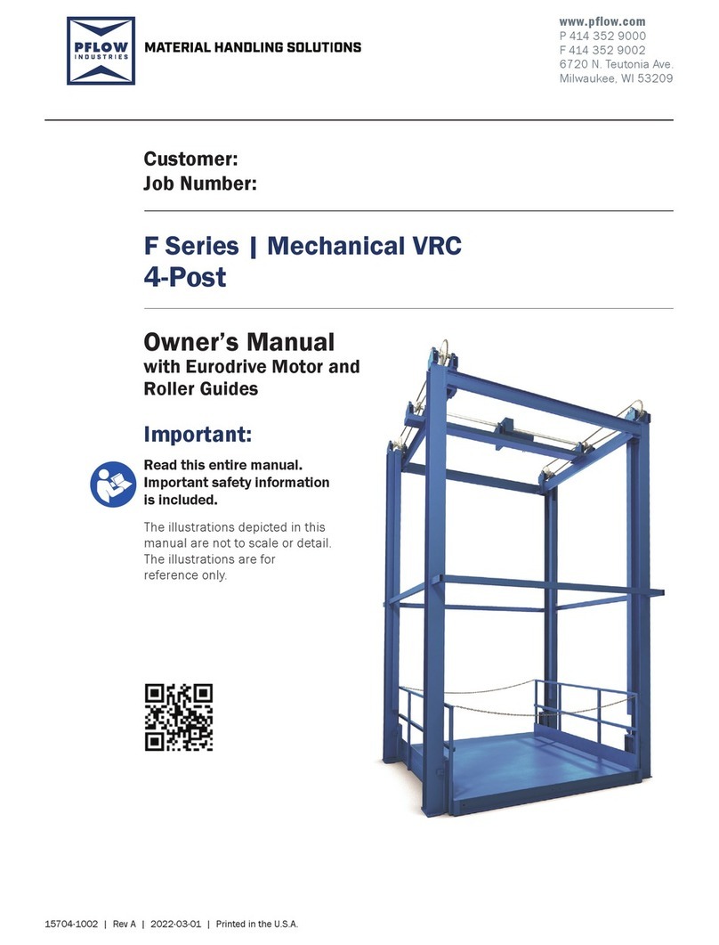
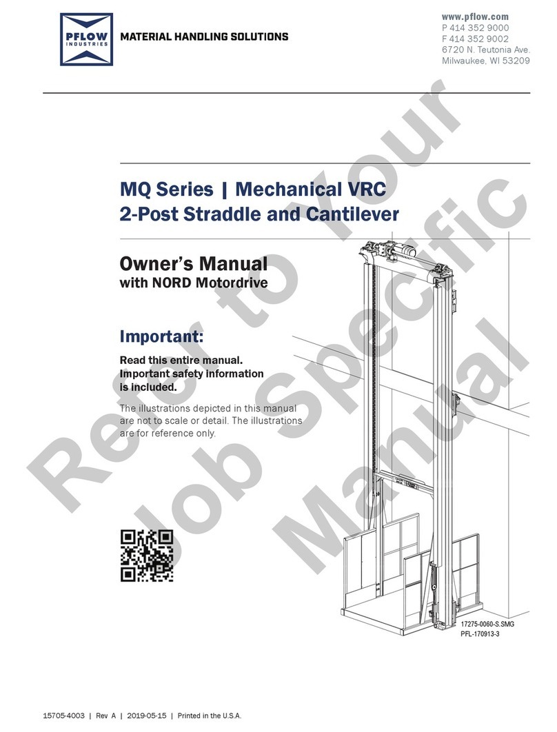
PFlow Industries F Series Installation and user guide

PFlow Industries

PFlow Industries F Series Installation and user guide

PFlow Industries 21 Series User manual

PFlow Industries

PFlow Industries 21 Series User manual

PFlow Industries 21 Series User manual

PFlow Industries

PFlow Industries 21 Series User manual

PFlow Industries B Series Quick start guide

PFlow Industries

PFlow Industries B Series Quick start guide

PFlow Industries Cartveyor CV Series User manual

PFlow Industries

PFlow Industries Cartveyor CV Series User manual

PFlow Industries B Series Quick start guide

PFlow Industries

PFlow Industries B Series Quick start guide

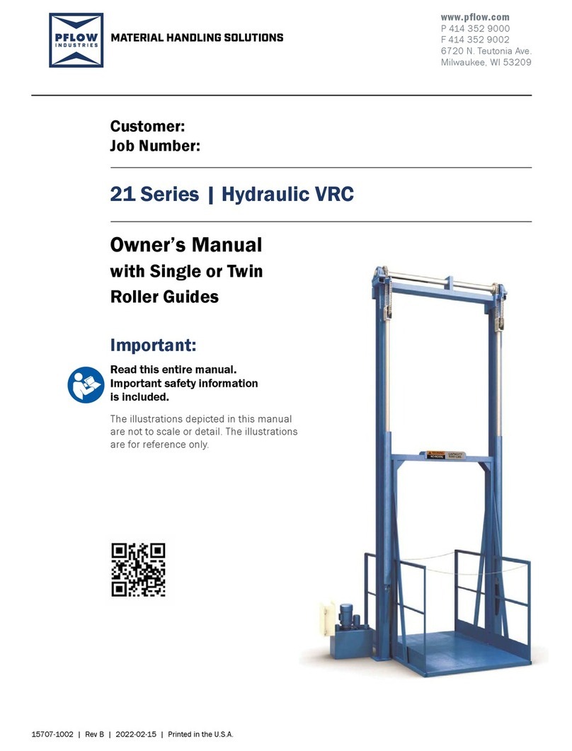
PFlow Industries 21 Series Hydraulic VRC User manual

PFlow Industries

PFlow Industries 21 Series Hydraulic VRC User manual

PFlow Industries MQ Series User manual

PFlow Industries

PFlow Industries MQ Series User manual

PFlow Industries F Series User manual

PFlow Industries

PFlow Industries F Series User manual

PFlow Industries 21 Series User manual
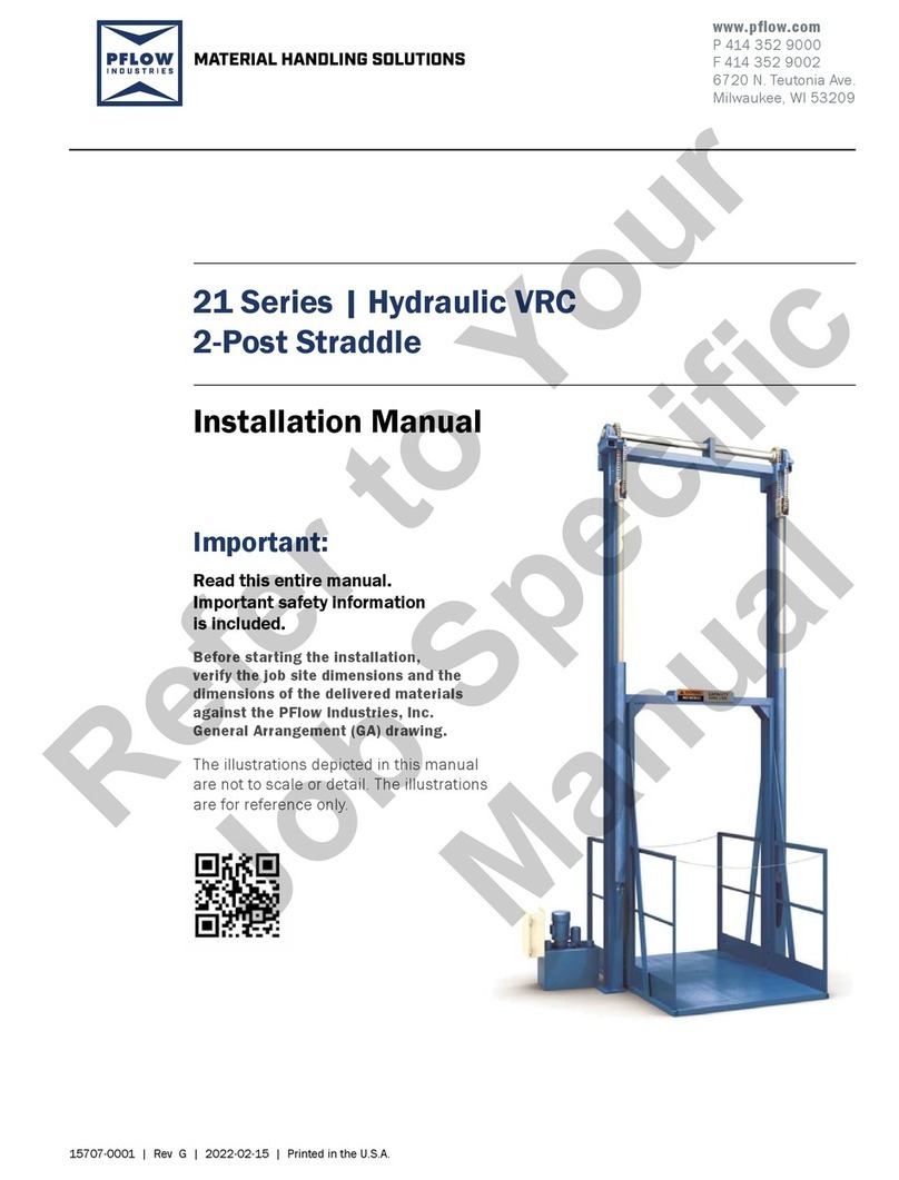
PFlow Industries

PFlow Industries 21 Series User manual
Popular Lifting System manuals by other brands

Rotary SL235MP installation instructions

Rotary

Rotary SL235MP installation instructions

U-Line H-10646 manual

U-Line

U-Line H-10646 manual

OYPLA DIY 3048 user manual

OYPLA DIY

OYPLA DIY 3048 user manual

Advance Lifts 100 Series owner's manual

Advance Lifts

Advance Lifts 100 Series owner's manual

morse 400A-96SS-114 Operator's manual

morse

morse 400A-96SS-114 Operator's manual

Hi-Force HVL Series instruction manual

Hi-Force

Hi-Force HVL Series instruction manual

Nihon Bisoh BISOMAC 308 Operator's manual

Nihon Bisoh

Nihon Bisoh BISOMAC 308 Operator's manual

Vestil EHLTD Series manual

Vestil

Vestil EHLTD Series manual

Ricon S2000 Series operating instructions

Ricon

Ricon S2000 Series operating instructions

AUTOLIFT AUTOLift3000 user manual

AUTOLIFT

AUTOLIFT AUTOLift3000 user manual

EDMA EDMAPLAC MEGA INSTRUCTION AND SECURITY MANUAL

EDMA

EDMA EDMAPLAC MEGA INSTRUCTION AND SECURITY MANUAL

ThyssenKrupp orion installation manual

ThyssenKrupp

ThyssenKrupp orion installation manual

North American Ramps CHECK OUT ProMaster MANUAL & SAFETY INSTRUCTIONS

North American Ramps

North American Ramps CHECK OUT ProMaster MANUAL & SAFETY INSTRUCTIONS

De Liftfabriek Shuttle instruction manual

De Liftfabriek

De Liftfabriek Shuttle instruction manual

Paragon Pro PANEL LIFT 117 Operator's manual

Paragon Pro

Paragon Pro PANEL LIFT 117 Operator's manual

TradeQuip 1001T owner's manual

TradeQuip

TradeQuip 1001T owner's manual

stellar labs Flex Series owner's manual

stellar labs

stellar labs Flex Series owner's manual

Stannah 320 manual

Stannah

Stannah 320 manual

manuals.online logo
manuals.online logoBrands
  • About & Mission
  • Contact us
  • Privacy Policy
  • Terms and Conditions

Copyright 2025 Manuals.Online. All Rights Reserved.