manuals.online logo
Brands
  1. Home
  2. •
  3. Brands
  4. •
  5. Phantom
  6. •
  7. Accessories
  8. •
  9. Phantom Tensioned Sports Cage System User manual

Phantom Tensioned Sports Cage System User manual

Page 1of 9
Phantom™ Tensioned Sports Cage
Installation Instructions
Parts List for Standard-Span Systems:
(1) Phantom™ Tensioned Sports Cage with three (3) top tensioning cables installed
(3) 2:1 Tensioning Assemblies with black nylon tensioning halyards
(3) Telescoping Reach Poles*
(3) Intermediate Cables (only for spans over 69’ for 55’ cage and 84’ for 70’ cage)
*Short-Span Systems omit Reach Poles and substitute the following:
(3) Anchor-End Blocks with black nylon anchoring halyards
(3) Rope Cleats
(6) 1/4”-20 x 2” Pan Head Screws
Additional Parts Required (must be supplied by customer):
(6) 3/8” steel eyebolts
(6) wall anchors to receive 3/8” eyebolts rated to support a minimum 250-lb. load
(6) wall anchors to receive 1/4” screws for Rope Cleats (Short-Span Systems only)
Tools Required for Set-up:
- pliers
- step ladder
- drill
Page 2of 9
Initial Set-Up Procedure:
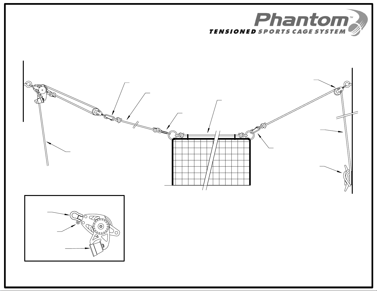
1. Determine which wall in your facility to define as the Tensioning Wall and which
to define as the Anchoring Wall (see Figures 1-1 and 2-1, or 4-1 for Short-Span
Systems). The Tensioning Wall will have the 2:1 Tensioning Assemblies
attached to it with tensioning halyards hanging down to the floor. These halyards
can be gathered and pulled to the side, or lifted and hung out of reach if needed.
This should be taken into consideration so as to avoid interfering with doorways,
etc. The same is true of the Anchoring Wall for Short-Span Systems as the
anchoring halyards will also hang down and must connect to the Rope Cleats.
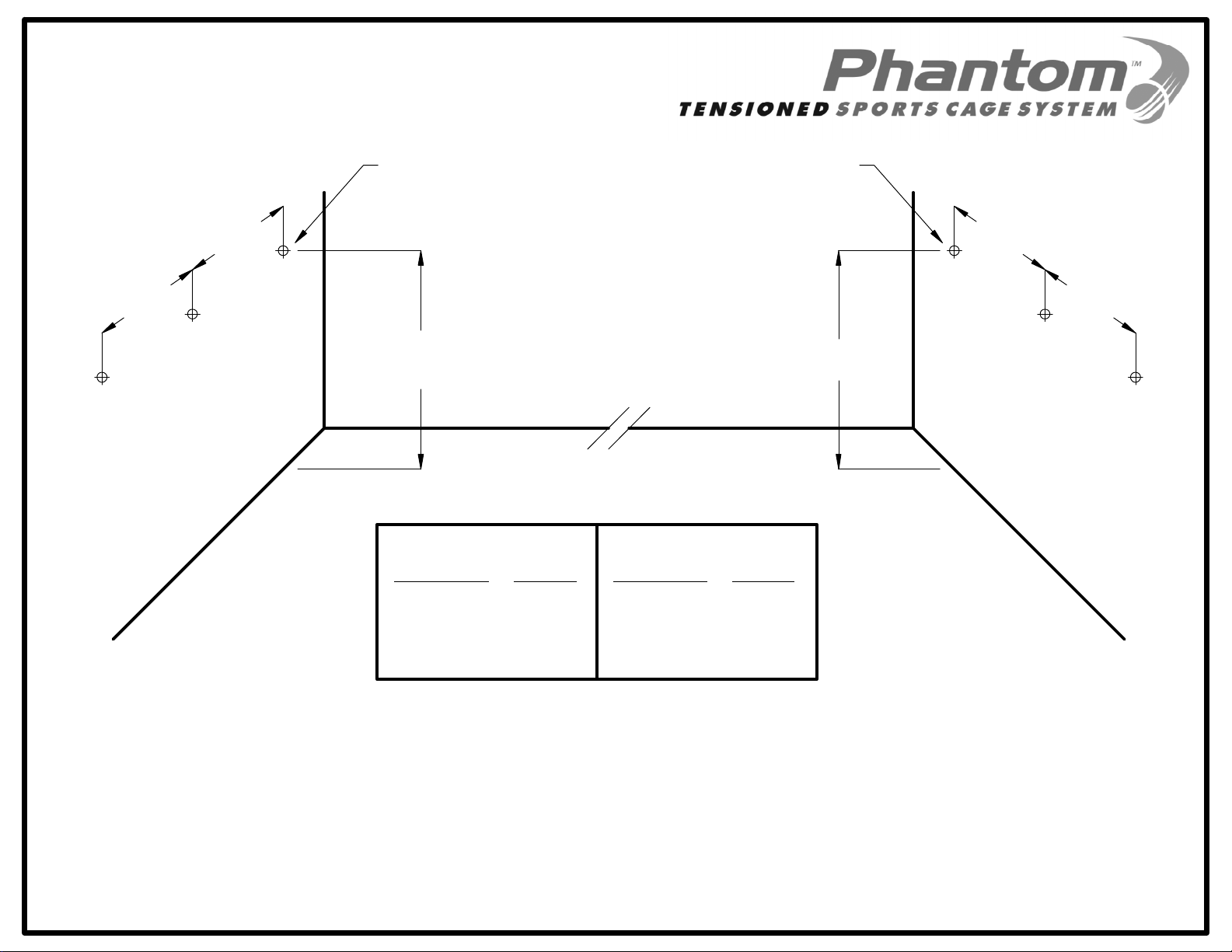
2. For the initial set-up, position and install the appropriate wall anchors and
eyebolts according to Figure 1-1 prior to attaching the tensioning hardware. Be
sure to account for any adjustment needed to the mounting height on the
Tensioning Wall as noted in the chart at the bottom of Figure 1-1 – this is based
on your wall span.
3. Once all eyebolts are installed, attach one Tensioning Block to each eyebolt on
the Tensioning Wall by unscrewing the clevis pin to remove the clevis (see Inset
“A” on Figure 2-1). You may need pliers to loosen the pin initially. Hang the
clevis onto the eyebolt, re-insert the pin to attach the Tensioning Block, and
tighten by hand. Make one last 1/4 turn with the pliers to ensure it is secure.
4. While holding onto the bit clip at the end of the 2:1 Tensioning Assembly, pull the
halyard down towards the floor. Be sure the halyard is not engaged in the cam-
lock and can move freely through the Tensioning Block. Attach the bit clip to the
halyard itself on the LOWER side of the knot that is located 9 feet from the end of
the halyard. The bit clip should be attached here and the 2:1 Tensioning
Assembly stored in this fashion at all times when not in use. This is done to
prevent the bit clip from accidentally drawing back up to the Tensioning Block
and out of reach. The knot has been intentionally placed in the halyard for you
for the same purpose – to prevent the end of the halyard from sliding up and out
of reach. Repeat Steps 3-4 for each of the other eyebolts on the Tensioning
Wall.
5. Lay the cage net out and stretch it across the floor with the steel rings extended
towards each wall. The three Tensioning Cables should be left resting on top.
If you received Reach Poles with your shipment, proceed to the following section
entitled, “Anchoring Wall Attachment for Standard-Span Systems”.
If you received Anchor-End Blocks with anchoring halyards and rope cleats,
continue to Step 6.
Page 3of 9
6. Attach one Anchor-End Block to each eyebolt on the Anchoring Wall by
unscrewing the clevis pin to remove the clevis (similar to procedure for
Tensioning Blocks in Step 3). You may need pliers to loosen the pin initially.
Hang the clevis onto the eyebolt, re-insert the pin to attach the Anchor-End
Block, and tighten by hand. Make one last 1/4 turn with the pliers to ensure it is
secure.
7. While holding onto the bit clip at the end of the anchoring halyard, pull the
halyard down towards the floor. Attach the bit clip to the halyard itself on the
LOWER side of the knot that is located 18 inches from the end of the halyard.
The bit clip should be attached here and the anchoring halyard stored in this
fashion at all times when not in use. This is done to prevent the bit clip from
accidentally drawing back up to the Anchor-End Block and out of reach. Repeat
Steps 6-7 for each of the other eyebolts on the Anchoring Wall.
8. Locate and install each of the three Rope Cleats to correspond with each of the
anchoring halyards as is convenient and practical for your facility. Tie the end of
each anchoring halyard permanently to the corresponding Rope Cleat. This is
done to prevent the end of the anchoring halyard from accidentally sliding up and
out of reach.
Proceed to the section entitled, “Anchoring Wall Attachment for Short-Span
Systems”.
Anchoring Wall Attachment for Standard-Span Systems:
1. Extend the Reach Poles to full length and lock in place (see Figure 3-1).
Connect the hook end of one reach pole to an eyebolt on the Anchoring Wall
(see Figure 2-1). Repeat this step for each of the three eyebolts on the
Anchoring Wall.
This step should be done from the ground - no ladders are required!
2. Attach the bit clip on the end of each Reach Pole to the steel ring on the end of
the appropriate corresponding Tensioning Cable on the net. This completes the
necessary attachments at the Anchoring Wall.
Proceed to the section entitled, “Tensioning Wall Attachment (all systems)”.
Page 4of 9
Anchoring Wall Attachment for Short-Span Systems:
1. Attach the bit clip on the end of each anchoring halyard to the steel ring on the
end of the appropriate corresponding Tensioning Cable (see Figure 4-1). Hoist
up each halyard so the end of the net will hang at least 3 feet away from the
Anchoring Wall. Wrap the halyard onto the Rope Cleat to secure it in place. This
completes the necessary attachments at the Anchoring Wall.
Proceed to the section entitled, “Tensioning Wall Attachment (all systems)”.
Tensioning Wall Attachment (all systems):
1. If included, attach one Intermediate Cable to each of the steel rings on the ends
of the Tensioning Cable nearest the Tensioning Wall (see Figures 2-1 or 4-1).
Please remember, not all systems include Intermediate Cables. If your system
does not include Intermediate Cables, you can skip this step and proceed to the
next.
2. Unhook the bit clip on the end of each 2:1 Tensioning Assembly from the halyard
and attach it to the steel ring on the end of the appropriate corresponding
Tensioning Cable (or Intermediate Cable if included).
3. Grab the end of one of the halyards and pull straight down to hoist the cage up
into position. As the cable tension increases, the halyard will slide into the cam-
lock and be held in place automatically if/when the halyard is released. Be sure
to pull the halyard straight down parallel with the wall to engage the cam-lock. If
the angle with the wall is too great, the cam-lock may not engage properly.
Repeat this step for each of the three halyards and adjust as necessary until
desired tension* (cage height) is reached.
* Please Note: It is not necessary to put excessive tension on the system – it is
designed to function properly even under minimal tension with as much as 24” of
sag across the span.
This completes the set-up – you are now ready to begin using the cage.
After the initial installation of the 2:1 Tensioning Assemblies, the set-up time
required for the Phantom™ Tensioned Sports Cage System should be less than
5 minutes from storage to hitting!
4. To lower and remove the cage, pull each halyard out away from the wall towards
the cage slightly – this will disengage the cam-locks and free the halyards,
allowing the cage to drop to the ground freely. Be sure to hold on to the halyards
securely to prevent them from slipping through your hands uncontrollably.
Page 5of 9
5. Follow the set-up instructions in reverse to disconnect the cage and remove
Reach Poles. Be sure to attach the bit clips on the ends of the 2:1 Tensioning
Assemblies to the LOWER side of the knot on each halyard as previously
mentioned. The halyards can be gathered and pulled to the side, or lifted and
hung out of reach if needed.
6. When packing the net for storage, the goal is to avoid tangling the cables and
losing the end rings, thereby simplifying set-up for the next use. Begin by
bringing the three Tensioning Cables together. The easiest way to do this is to
have one person at each end of the lowered cage. Each person collects the
three cables and pulls tension between each other so that the cables run
adjacent and parallel to one another.
7. Lay the cables down and push the sides of the cage inward until you have a full
length row of net about 2’ wide with the cables on top.
8. Place your storage container (such as the Phantom™ Tensioned Sports Cage
Storage Cart) near middle of the net. Grabbing the net in the middle, carefully lift
and place it down in the bottom of the container so as not to snag it on anything.
Keep loading the net in from both sides equally until the entire cage is in the
container and the three steel rings from each end of the cage are left hanging out
opposite sides of the container’s top opening.
9. To deploy the cage the next time, set the storage container in the middle of the
designated cage area. Have two people each take one set of steel rings and pull
the net out of the container as they walk toward opposite walls.
Thank you for your purchase of the Phantom™ Tensioned Sports Cage System!
We hope you enjoy the simplicity and ease of use it provides.
7'-6"
7'-6"
7'-6"
7'-6"
SEE CHART
BELOW 14'-0"
TENSIONING
WALL
ANCHORING
WALL
FIGURE 1-1
SIX (6) 3/8-INCH DIA. STEEL EYEBOLTS
RE UIRED PER CAGE*
WALL ANCHOR POSITIONING
* EYEBOLTS AND WALL ANCHORS ARE NOT INCLUDED.
IT IS THE RESPONSIBILITY OF THE END USER TO PROVIDE THE EYEBOLTS
AND WALL ANCHORS APPROPRIATE FOR THEIR WALL CONDITION.
WALL ANCHORS MUST BE RATED TO SUPPORT A MINIMUM LOADING OF 250 LBS.
AND SIZED TO RECEIVE A 3/8" THREADED EYEBOLT.
TENSIONING WALL MOUNTING HEIGHTS
UP TO 80'
80' - 90'
90' - 100'
100' +
14'-0"
14'-6"
15'-0"
CALL
WALL SPAN HEIGHT
55' Phantom™ Cage
UP TO 100'
100' - 110'
110' - 120'
120' +
14'-0"
14'-6"
15'-0"
CALL
WALL SPAN HEIGHT
0' Phantom™ Cage
PLEASE NOTE: IT IS NORMAL TO EXPECT 18" TO 24" OF SAG
THROUGHOUT THE CAGE, ALTHOUGH LESS CAN BE
ATTAINED BY INCREASING TENSION ON THE HALYARDS.
INTERMEDIATE CABLES ARE INCLUDED FOR SPANS OVER
6 ' FOR A 55' CAGE AND 84' FOR A 70' CAGE.
FIGURE 2-1
STANDARD-SPAN ATTACHMENT DETAIL
TENSIONING
WALL
TENSIONING CABLE
REACH POLE
ANCHORING
WALL
2:1 TENSIONING ASSEMBLY
BIT CLIP
BIT CLIP
CAM-LOCK
INSET "A" - TENSIONING BLOCK DETAIL
CLEVIS
CLEVIS PIN
INTERMEDIATE CABLE
(IF INCLUDED)
BIT CLIP
TENSIONING
HALYARD
REACH POLE SHORTENED FOR STORAGE
REACH POLE EXTENDED FOR USE
USE TWIST-LOCK TO SECURE POLE
POSITION FOR STORAGE/USE
FIGURE 3-1
TELESCOPING REACH POLE INSTRUCTIONS
PLEASE NOTE: IT IS NORMAL TO EXPECT 18" TO 24" OF SAG
THROUGHOUT THE CAGE, ALTHOUGH LESS CAN BE
ATTAINED BY INCREASING TENSION ON THE HALYARDS.
INTERMEDIATE CABLES ARE INCLUDED FOR SPANS OVER
6 ' FOR A 55' CAGE AND 84' FOR A 70' CAGE.
FIGURE 4-1
SHORT-SPAN ATTACHMENT DETAIL
TENSIONING
WALL
TENSIONING
HALYARD
TENSIONING CABLE
ANCHOR-END BLOCK
ANCHORING
WALL
2:1 TENSIONING ASSEMBLY
BIT CLIP
BIT CLIP
CAM-LOCK
INSET "A" - TENSIONING BLOCK DETAIL
CLEVIS
CLEVIS PIN
INTERMEDIATE CABLE
(IF INCLUDED)
BIT CLIP
ROPE CLEAT
ANCHORING
HALYARD

Popular Accessories manuals by other brands

Kompernass KAA 31 A1 operating instructions

Kompernass

Kompernass KAA 31 A1 operating instructions

Mutsy Spider instruction manual

Mutsy

Mutsy Spider instruction manual

Tecumseh F31HC Installation, Operation, Service and Maintenance Instructions

Tecumseh

Tecumseh F31HC Installation, Operation, Service and Maintenance Instructions

Kampa Jamboree instructions

Kampa

Kampa Jamboree instructions

weinor Aruba Rund Maintenance instructions and directions for use

weinor

weinor Aruba Rund Maintenance instructions and directions for use

serene living DEWDROPOIL Instructions & Care

serene living

serene living DEWDROPOIL Instructions & Care

Saniswiss SANIPOD user manual

Saniswiss

Saniswiss SANIPOD user manual

PCB Piezotronics IMI SENSORS HT640B71 Installation and operating manual

PCB Piezotronics

PCB Piezotronics IMI SENSORS HT640B71 Installation and operating manual

My Junior My Kiddyboard manual

My Junior

My Junior My Kiddyboard manual

KITA KFP02 Series instruction manual

KITA

KITA KFP02 Series instruction manual

Bang & Olufsen BEOLINE Guides & online training

Bang & Olufsen

Bang & Olufsen BEOLINE Guides & online training

SKF CMWA 8800 Service manual

SKF

SKF CMWA 8800 Service manual

KROHNE OPTISENS TSS 2000 Handbook

KROHNE

KROHNE OPTISENS TSS 2000 Handbook

emporium NEERA WBECEM003 quick start guide

emporium

emporium NEERA WBECEM003 quick start guide

Panasonic KX-HNS104C installation guide

Panasonic

Panasonic KX-HNS104C installation guide

fontastic Eta user manual

fontastic

fontastic Eta user manual

Omron ZX-T - Operation manual

Omron

Omron ZX-T - Operation manual

Grandstream Networks UCM6100 Series user manual

Grandstream Networks

Grandstream Networks UCM6100 Series user manual

manuals.online logo
manuals.online logoBrands
  • About & Mission
  • Contact us
  • Privacy Policy
  • Terms and Conditions

Copyright 2025 Manuals.Online. All Rights Reserved.