manuals.online logo
Brands
  1. Home
  2. •
  3. Brands
  4. •
  5. Phantom
  6. •
  7. Projection Screen
  8. •
  9. Phantom Executive 4" User manual

Phantom Executive 4" User manual

4” Executive Recessed Installation Manual
-1 of 8 –
Version 2. – 06/11/09
Section A. The First Trip
1. Installing the Roller Assembly
2. Installing the U-Channel
Section B. The Second Trip
1. Connect the Motor to Electrical Power
2. Installing the Mesh
3. Installing the Slide Bar
4. Installing the Bottom Brush Seals
5. Installing the Side Tracks
6. Setting the Motor Limits
7. Setting the Top Limit
8. Setting the Bottom Limit
9. Final Motor Wiring
L- Important Information
Inspect the shipping container for any
shipping damage before proceeding to step 1.
LYou may want to check your unit before
going to the job site, especially if you must
travel a lengthy distance or obtain rental of
any special lift equipment. You will be able to
identify each box by the customer tag you
previously assigned to each of the units. You
may use the packing slip to assist you to
double check for correct sizes and
measurements.
It is recommended that the installation of a
recessed unit take at least two trips, with the
U-channel and roller assembly installed during
the early part of construction. The second
trip to finish the install at or near the end of
construction
Unpacking the Unit:
Unpack the unit and check for the following:
•Roller mounting brackets
•Roller
•Motor
•U-channel
•Recessed side tracks
•Recessed side track clips
•Slide bar
•Probes (pair)
•Bottom Brush Seal
•Mesh (always shipped separate)
•Control accessories as ordered
•Screw (fastener) pack
•Track Entry Guide set
A. THE FIRST TRIP:
When you go to the job site, make sure you
know the dimensions that the cavity needs to
be built to for both the U-channel and the
cavity for the unit. This should have been
coordinated between the builder, architect, or
homeowner before the order was submitted
and would have been dictated by the
dimension of the unit. Refer to the Planning
and Measuring Manual with appropriate
appendixes for further instruction.
1.
1. Installing the Roller Assembly
It is recommended that before you install the
U-channels, that you install the roller tube
assembly. Since the 4” Executive does not
have a spring loaded pivot, installing the tube
later (collapsing the tube or not) is more
difficult that with the larger Executives.
4” Executive Recessed Installation Manual
-2 of 8 –
Version 2. – 06/11/09
LIf the above is not possible, it is
recommended to build a temporary box to
replicate the agreed upon cavity size and write
“RECESSED ROLL SCREEN GOES
HERE”. In this temporary cavity, you can
also indicate where the electrical service is to
be located, and any other service information
that the other sub-trades on site may require.
Determine the location where the roller
mounting brackets will be installed in the
cavity. Be sure to pre-drill for mounting holes
(minimum of 3) into each bracket.
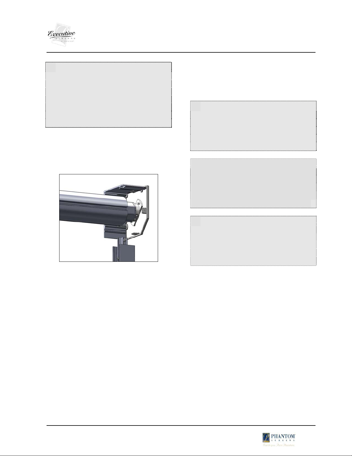
Recessed roller mounting brackets
Determine where the electrical wire will be
routed and make sure the wire is on the
correct side of the roller before it is installed.
Depending on your wiring, you may also want
to drill out the bracket for the wire with a
3/8” drill bit.
Mount the pivot side bracket into the cavity.
Slide the motor end cap onto the motor
bracket (the two pins on the end cap mate to
the 2 holes in the bracket attached to the
motor) – ensure the limits face down, and the
motor wire faces the back corner of the
bracket.
While holding the motor end cap bracket
onto the motor (and holding motor into insert
at the same time) install the roller assembly by
inserting the idler bushing onto the post on
the bracket and then lift the assembly up and
secure the motor side bracket in place.
LThe roller must be installed level to
ensure proper roll up so you may need to
shim as needed to achieve this. There should
be no more than 1/16” of side to side
movement in the roller, so you may need to
adjust the bracket location as needed.
LIf there is over 1/16” but less than
3/16” of side to side movement in the roller,
rather than moving a bracket, it may be easier
to remove the screw securing it in and slide
the plastic bushing out of the idle insert by a
MAXIMUM of 1/8” and re-secure in place.
LThe screws through the roller mounting
brackets will be holding the entire weight of
the unit, do not undersize these fasteners
and be sure to continue to support the roller
assembly until you have installed the roller
mounting brackets completely.
After the roller assembly has been installed
make sure there is a drip loop in the electrical
cord leading from the motor so water cannot
back flow into the unit and damage the
motor.
4” Executive Recessed Installation Manual
-3 of 8 –
Version 2. – 06/11/09
Drip loop on the motor cable inside of the cavity
2.
Installing the U-Channel
Install the U-channels from the bottom of the
cavity to the floor in the space designated.
Make sure that the U-channels are level, and
located where the installation specifications
dictate. Phantom Screens recommends that
you place covers over the U-channel opening
to keep debris out during construction. Verify
with the builder to ensure there are no railings
or other items being installed within ½ inch
of the U-channel that would impede with the
movement of the slide bar and bottom brush
seal.
LIdentify which end of the cavity has
electrical power available.
B. THE SECOND TRIP:
At the job site ensure that the U-channels
have not been moved if they were installed
prior to installation of the unit. Remove all
protective coverings and any foreign material
from the opening in the U-channel. Remove
the temporary cavity (if used) and inspect the
cavity for unwanted obstructions (nails,
screws and staples). Check for the electrical
power supply and determine how each unit’s
power source will be isolated during, and after
installation.
1. Connect the Motor to Electrical Power
:
Somfy strongly recommends using a Tester
Cable (T.C.) for installation to ensure the
system is operating correctly before the final
electrical connection is made.
Ensure the tester cable switch is in the center
“off” position and connect the tester cable to
the motor leads by matching color codes.
Identify the “up” limit screw by finding the
arrow on the motor head that which points in
the direction that retracts (rolls up) the unit.
Turn the power to the unit on and ensure that
the switch is operating properly (“Up” raises,
“down” lowers). If not, turn the power to the
unit off and simply reverse the red and black
motor leads.
2. Installing the Mesh
Run the motor in the down direction until it
stops at its pre-set lower limit. Determine the
front of the mesh. The zipper flange is on the
back of the mesh and will be butted up to
within 1/16” of the zipper teeth on the front.
Determine the top of the mesh (zipper tabs
will always be at the bottom) and slide the top
zipper one of the zipper ports on the roller
(usually the one closest to the bottom).
Top of the mesh Bottom of the mesh
4” Executive Recessed Installation Manual
-4 of 8 –
Version 2. – 06/11/09
After installing the mesh on the roller, the top
zipper should have the same number of
zipper teeth extending past the roller at both
ends so that the mesh is centered on the roller
There should be 3 (Maximum of 4) zipper
teeth extending per side. Insert the mesh pins
between the zipper teeth in the zipper port at
each end of the roller. The head of the mesh
pin goes in between the third and fourth
zipper teeth.
Three teeth showing Mesh pin installation
These mesh pins hold the mesh in place on
the roller assembly, and prevent the mesh
from shifting side to side during roll
up/down.
3. Installing the Slide Bar
Hold the “up” button on the tester switch or
remote until the bottom of the mesh is at a
comfortable working height (around 3’ off the
floor). Take the time to ensure the mesh is
rolling up straight on the roller and does not
get caught on anything that can tear it.
LIf the mesh will not roll up to a
comfortable height, you will need to adjust
the upper limit on the motor. See the section
on Setting Limits for further instructions.
Install the slide bar on the bottom zipper by
folding one of the tabs at the bottom of the
mesh back at a 45-degree angle. Install the
zipper into the bottom most slide bar zipper
port.
Mesh tab folded 45º Bottom zipper inserted
LCaution – the slotted portions of the
slidebar zipper port are sharp, use caution to
avoid damaging the mesh when inserting it.
The slide bar should stop at the other zipper
tab, which is hanging straight down on the
opposite end of the slide bar. At this point
you can insert the probe with the round
tubing at the top, (you should not see the “x”
shapes in the bottom of the probe).
Slide the zipper tab into the space between
the legs of the probe, which are protruding
from the end of the slide bar.
Mesh tab in line with the probe and being inserted
Stop positioning the mesh tab when the end
of the probe is flush with the zipper stitching.
Once the tab is positioned correctly on the
zipper flange install two black #6 x ½”
stainless steel wood screws (supplied in the
screw pack) through the arch shaped guides
on the legs of the probe tighten them so the
probe pinches the zipper tab.
4” Executive Recessed Installation Manual
-5 of 8 –
Version 2. – 06/11/09
LMake sure that the screws go through the
probe straight and exit on the other side
through the arch shaped guides.
LIf you choose to, you can pre-drill the
probes before inserting the screws using a
3/32” drill bit or smaller.
#6 ½” wood screw being inserted into the probe
LDo not install screws through the
stitching (thread) and do not over tighten.
LDO NOT remove any screws from the
slide bar as this will result in movement of the
weight bars and potentially cause uneven
rollup of the mesh.
Proceed to the other end of the slide bar and
install the second zipper tab exactly like the
first.
4. Installing the Bottom Brush Seals
Before you insert the bottom brush seals into
the bottom brush seal ports of the slide bar,
ensure that the end is cut square. Start the
bottom brush seal on one end, and slide it all
the way across the slide bar port. If you are
having problems getting the bottom brush
seal to feed the length of the slide bar, spray
the length of the port with silicone.
Bottom brush inserted into the slide bar ports
With a pair of scissors or a knife, trim the
bottom brush seals flush with the other end
of the slide bar.
LThe 4” Executive uses 2 bottom brush
seals, one on each side of the slidebar.
To keep them from moving, crimp both ports
at each end of the slidebar.
5.
Installing the Side Tracks:
Measure from the top of the U-channel
(which should be flush with the bottom of the
cavity) to the finished surface (or bottom of
the unit). Measure both sides of the opening,
as they may be different.
LIf only the slide bar is being pulled into
the cavity you need only add 1 ½” to the
length of the sidetrack. However if you are
going to bring both the slide bar and bottom
brush seal into the cavity you will need to add
2 1/2” (minimum) to the side track length.
4” Executive Recessed Installation Manual
-6 of 8 –
Version 2. – 06/11/09
Identify the left track from the right. Measure
from the top of the sidetrack to the bottom
and cut each sidetrack to its desired length.
Install the recessed sidetrack clips. The first
clip should be located at approximately 6”
from the bottom. The remainder of the clips
are placed at a maximum of 24” apart. The
top clip should not be more than 9” from the
top of the actual track itself.
LYou should pre-plan your clip locations
for an even appearance, and to avoid
overlapping screws securing the U-Channel.
Recessed side track, clip and screws to fasten together
To install track entry guides supplied with
your unit, they should be affixed to the top of
the track at this time and before the tracks are
installed into the U-channel. To secure the
track entry guide to the top of the recessed
track, affix a 6 x ½” TEK screw through the
side of the track entry guide and through the
track.
Screw inserted through the track entry guide and into
the recessed track.
With the slide bar at the top, hold the zipper
flange and guide the zipper into the top
counter sunk end of the entry guide and into
the zipper ports of the tracks.
With the clips fastened to the recessed tracks,
snap into the U- channels. Be careful not to
push the clips in to the U-channels too far as
it is easier to push them in than pull them out
to adjust.
LWith the slidebar just barely above the
floor, the location of the mesh hanging in the
u-channels will give you a good idea of where
the final track location should be.
Press the down button to lower the slidebar
and guide the zippers down into the side
tracks. You may have to adjust the side tracks
in the U- channels as you bring the slide bar
down. Ensure the mesh feeds straight down
into both tracks, and that both tracks are
plumb.
LDo not pull the screen or the zippers too
taught. The zippers should be feeding straight
down parallel to each other into the tracks.
4” Executive Recessed Installation Manual
-7 of 8 –
Version 2. – 06/11/09
Run the mesh up and down, adjusting the side
tracks in or out as needed. Ensure a nice tight
roll on the tube when rolled and that the
slidebar hangs level.
LIf you cannot get the slidebar to hang
level, such as in the case of a tapered mesh,
add a small shim to the tube on the end that
the slidebar hangs lowest. This will act to
increase the diameter on that end and cause
the mesh to roll up faster on that end to
compensate. Caution – a little does a lot.
Start with a very small shim (like the size of a
single 1’ strip of duct tape) and add more as
needed. Use a material that will not degrade.
When you are done, add the second screw to
lock the clips in place. Silicone the side tracks.
6. Setting the Motor Limits
LRecessed hex screws in the motor head
can accommodate a flat head screwdriver
(4mm wide max.), Somfy Allen wrench (Cat.
No. 6500258) or flexible limit switch adjuster
(Cat. No. 6500091)
LDO NOT use a drill or any other power
tool to adjust the limits or they could be
permanently damaged.
LThe motors have a built-in thermal cut-
off. If after several minutes of use the motor
will not rotate in either direction, allow the
motor to cool for a few minutes.
Looking up at the motor, the bottom limit
is the one closest to the mesh, regardless
of left or right motor location.
7. Setting the Top Limit
Run the motor in the up direction, stopping it
a few inches below the desired final height.
The top of the slide bar should not be more
than ½ inch above the end of the tracks, and
the probe must never be above the top of the
tracks.
If the motor did not stop on its own before
this point, the pre-set upper limit on the
motor is higher than desired.
To decrease the height of the upper limit, turn
the up adjuster on the head of the motor (the
one furthest from the mesh) toward the “-”
(Clockwise) as much as required so that the
motor stops on its own when it reaches the
desired height.
To do this, turn the adjuster a few (around 5)
rotations then lower the screen a foot and
raise it again. Repeat with decreasing number
of rotations each time until the motor stops
on its own at exactly the desired height.
Bottom limit
adjuster
T
op limit
adjuster
4” Executive Recessed Installation Manual
-8 of 8 –
Version 2. – 06/11/09
If the motor stops on its own before it
reaches the desired height, the motor has
likely reached its pre-set upper limit.
Run the motor a couple inches in the down
direction to ensure the motor did not stop
due to thermal cut-off.
To increase the height of the upper limit, turn
the up adjuster on the head of the motor (the
one furthest from the mesh) toward the “+”
(Counterclockwise) as much as required to
allow it reach the desired final height. Test
every few rotations to avoid over-shooting.
8. Setting the Bottom Limit
Run the motor in the down direction,
stopping it a few inches above the desired
final height. Usually this would be where the
brush pile forms a “seal” with the floor.
If the motor did not stop on its own before
this point, the pre-set bottom limit on the
motor is lower than desired.
To increase the height of the bottom limit,
turn the Bottom limit adjuster on the head of
the motor (closest to the mesh) toward the
“-” (Clockwise) as much as required so that
the motor stops on its own when it reaches
the desired height.
As with the Upper limit, test every few
rotations to avoid over-shooting.
If the motor stops on its own before it
reaches the desired height, the motor has
likely reached its pre-set bottom limit.
Run the motor a couple inches in the down
direction to ensure the motor did not stop
due to thermal cut-off.
To lower the height of the bottom limit, turn
the bottom limit adjuster (the one closest to
the mesh) toward the “+” (Counterclockwise)
as much as required to allow it reach the
desired final height, testing every few
rotations to avoid over-shooting.
Ensure the slide bar is not resting on the
floor. This could effect tension on the mesh
and the mesh could sag at the bottom.
9. Final Motor Wiring
Disconnect tester and connect motor to
selected control option(s).
See Electrical Considerations – Conventional
Motors document
All electrical work being done must be in
accordance with all Local and National
Electrical Codes.

Popular Projection Screen manuals by other brands

Elite Screens EDGE FREE Aeon StarBright 9 Series user manual

Elite Screens

Elite Screens EDGE FREE Aeon StarBright 9 Series user manual

Elite Screens Kestrel Stage Series user guide

Elite Screens

Elite Screens Kestrel Stage Series user guide

SCREENLINE Living manual

SCREENLINE

SCREENLINE Living manual

Panasonic PT-40LC12-K operating instructions

Panasonic

Panasonic PT-40LC12-K operating instructions

Projecta Elpro electrol RF Mounting instruction

Projecta

Projecta Elpro electrol RF Mounting instruction

BRANDRUP FLYOUT 100 111 01S quick start guide

BRANDRUP

BRANDRUP FLYOUT 100 111 01S quick start guide

Euroscreen Linea TabTension manual

Euroscreen

Euroscreen Linea TabTension manual

Da-Lite PROFESSIONAL ELECTROL Instruction book

Da-Lite

Da-Lite PROFESSIONAL ELECTROL Instruction book

Draper Silhouette Series M Installation & operating instructions

Draper

Draper Silhouette Series M Installation & operating instructions

Da-Lite Parallax Instruction book

Da-Lite

Da-Lite Parallax Instruction book

Elite Prime Vision Polar Star Series user guide

Elite Prime Vision

Elite Prime Vision Polar Star Series user guide

AccuScreens WALL/PORTABLE PROJECTION SCREENS Assembly/mounting instructions

AccuScreens

AccuScreens WALL/PORTABLE PROJECTION SCREENS Assembly/mounting instructions

Elite Screens Electric100H Specifications

Elite Screens

Elite Screens Electric100H Specifications

SCREENLINE Big Lodo Evolution instructions

SCREENLINE

SCREENLINE Big Lodo Evolution instructions

LP Morgan Screenboard user manual

LP Morgan

LP Morgan Screenboard user manual

Cirrus Screens Harbour 2 manual

Cirrus Screens

Cirrus Screens Harbour 2 manual

Vutec ArtScreen installation instructions

Vutec

Vutec ArtScreen installation instructions

Music & Lights FullScreen SCSP Series user manual

Music & Lights

Music & Lights FullScreen SCSP Series user manual

manuals.online logo
manuals.online logoBrands
  • About & Mission
  • Contact us
  • Privacy Policy
  • Terms and Conditions

Copyright 2025 Manuals.Online. All Rights Reserved.