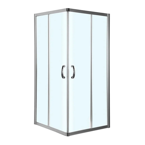
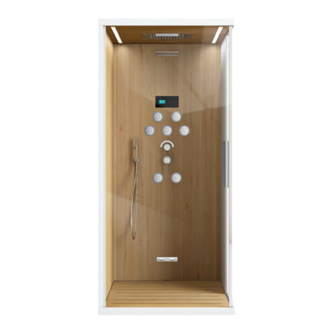
PHARO Duschtempel 115 DL 40 DeLuxe 29257 Series User manual

Pharo® Duschtempel® 115 DL 40 DeLuxe
Pharo® Duschtempel® 115 ST 40 Steam
Pharo® Duschtempel®
Duschtempel® 115 DL 40 DeLuxe (DT New Line DL) 29257xxx
Duschtempel® 115 DL 40 DeLuxe (DT New Line DL) 29157xxx
Duschtempel® 115 ST 40 Steam (DT New Line ST) 29247xxx
Duschtempel® 115 ST 40 Steam (DT New Line ST) 29147xxx
Duschtempel® 100 DL 40 DeLuxe (DT New Line DL) 29256xxx
Duschtempel® 100 DL 40 DeLuxe (DT New Line DL) 29156xxx
Duschtempel® 100 ST 40 Steam (DT New Line ST) 29246xxx
Duschtempel® 100 ST 40 Steam (DT New Line ST) 29146xxx
Montageanleitung
Installation Instructions
Istruzioni di montaggio
Instructions de montage
Instrucciones de montaje
Montagehandleiding
Návod k montáži
Instrukcja montażu
Ðóêîâîäñòâî ïî ìîíòàæó

Pharo® Duschtempel® 115 DL 40 DeLuxe
Pharo® Duschtempel® 115 ST 40 Steam
Pharo® Duschtempel®
29257xxx (Tür Linksanschlag)
29157xxx (Tür Rechtsanschlag)
29247xxx (Tür Linksanschlag)
29147xxx (Tür Rechtsanschlag)
29256xxx (Tür Linksanschlag)
29156xxx (Tür Rechtsanschlag)
29246xxx (Tür Linksanschlag)
29146xxx (Tür Rechtsanschlag)
29257xxx (Door with Left Stop)
29157xxx (Door with Right Stop)
29247xxx (Door with Left Stop)
29147xxx (Door with Right Stop)
29256xxx (Door with Left Stop)
29156xxx (Door with Right Stop)
29246xxx (Door with Left Stop)
29146xxx (Door with Right Stop)
29257xxx (Porta con anta a battente sinistro)
29157xxx (Porta con anta a battente destro)
29247xxx (Porta con anta a battente sinistro)
29147xxx (Porta con anta a battente destro)
29256xxx (Porta con anta a battente sinistro)
29156xxx (Porta con anta a battente destro)
29246xxx (Porta con anta a battente sinistro)
29146xxx (Porta con anta a battente destro)
Montageanleitung
Installation Instructions
Istruzioni di montaggio

3
Deutsch
DEUTSCH
Inhaltsverzeichnis 3
Masse DT 115 DL 40 DeLuxe/Steam 4
Masse DT 100 DL 40 DeLuxe/Steam 5
Bestandteile 6
Serviceteile 8
Technische Daten 12
Vorwort 14
In der Anleitung Verwendete Symbole
15
Sicherheitsvorschriften 16
Benötigtes Werkzeug 18
Montage Duschwanne 20
Montage Wannenfüsse 22
Montage Wanne 26
Montage Ablauf 30
Montage Wanne 32
Montage Haltewinkel 34
Montage Klemmleisten 36
Montage Dachauflagewinkel 40
Montage Dach 42
Montage Säulen 44
Montage Dach 50
Montage Sitz 52
Montage Klappsitz 54
Montage Eckschrank 56
Montage Eckpaneel 58
Montage Seitenscheibe 64
Montage Glastür 68
Endmontage 72
Funktionsprüfung 76
Thermostat justieren 80
Steuerung K IV lite Steam 82
Bedienung 94
Austausch Leuchtmittel 98
Reinigung 100
Entkalken 102
INHALTSVERZEICHNIS
English
ENGLISH
Contents 3
DimensionsofDT115DL40DeLuxe/Steam4
Dimensions of DT 100 DL 40 DeLuxe/
Steam 5
Components 6
Service Parts 8
Technical Data 12
Foreword 14
Symbols Used in the Instructions 15
Safety Precautions 16
Required Tools 18
Shower Tray Installation 20
Shower Tray Feet Installation 22
Shower Tray Installation 26
Drain Installation 30
Shower Tray Installation 32
Angle Bracket Installation 34
Wall Clamping Profile Installation 36
Top Support Bracket Installation 40
Top Installation 42
Column Installation 44
Top Installation 50
Seat Installation 52
Folding Seat Installation 54
Corner Cabinet Installation 56
Corner Panel Installation 58
Side Panel Installation 64
Glass Door Installation 68
Final Work 72
Functional Test 76
Thermostat Adjustment 80
K IV lite Steam Control 82
Operation 94
Replacement of Lighting 98
Cleaning 100
Decalcifying 102
CONTENTS
Italiano
ITALIANO
Indice 3
Ingombri DT 115 DL 40 DeLuxe/Steam4
Ingombri DT 100 DL 40 DeLuxe/Steam
5
Componenti 6
Parti di ricambio 8
Dati tecnici 12
Introduzione 14
Simboli utilizzati nel manuale 15
Norme di sicurezza 16
Utensili richiesti 18
Montaggio del piatto doccia 20
Montaggio dei piedi del piatto doccia
22
Montaggio del piatto doccia 26
Montaggio del deflusso 30
Montaggio del piatto doccia 32
Montaggio degli angolari di supporto
34
Montaggio del listello di bloccaggio36
Montaggio dell'angolare per
sostemere il cappello 40
Montaggio del cappello 42
Montaggio delle colonne 44
Montaggio del cappello 50
Montaggio del sedile 52
Montaggio del sedile pieghevole 54
Montaggio dell'armadietto angolare56
Montaggio del pannello angolare 58
Montaggio della pannello laterale 64
Montaggio della porta di vetro 68
Montaggio finale 72
Controllo del funzionamento 76
Taratura del termostato 80
Controllo K IV lite Steam 82
Comando 94
Sostituzione delle lampadine 98
Pulizia 100
Per togliere il calcare 102
INDICE

4
DT 115 DL 40 DELUXE
DT 115 ST 40 STEAM
MASSE DIMENSIONS INGOMBRI

5
DT 100 DL 40 DELUXE
DT 100 ST 40 STEAM
Deutsch
MASSE
English
DIMENSIONS
Italiano
INGOMBRI

6
BESTANDTEILE
Karton 1
A Wanne
B Wannenschürze (Option*)
Karton 2
C Dach mit Farblicht (Option*)
D Dachabdeckung (Option*)
Karton 3
E Säule mit Seitenbrausen (Opti-
on*)
F Säule mit Scharnieren (Rechtsan-
schlag)
G Klemmleiste (links)
H Klemmleiste (rechts)
I Dachauflagewinkel
Karton 4
J Eckpaneel
K Eckschrank mit Dampftechnik
inklu- sive Aromadispenser
(Option*)
L Revisionsscheibe
Karton 5
M Glastür
N Seitenscheibe (links)
O Seitenscheibe (rechts)
Karton 6 (in Karton 4)
P Zubehör (Befestigungsteile)
Q Handbrause Aktiva A8
R Brauseschlauch
S Ablauf
Karton 7 (in Karton 4)
T Klappsitz mit Rückenpad
* Alle mit "Option" gekennzeichneten
Teile können separat bestellt werden.
Lediglich in den DeLuxe Versionen sind
das Dach mit Farblicht, die Säulen mit
Seitenbrausen und derAromadispenser
bereits enthalten.
COMPONENTS
Carton 1
A Shower tray
B Shower tray skirting (option*)
Carton 2
C Top with colour lighting (option*)
D Top cover (option*)
Carton 3
E Column with body shower (opti-
on*)
F Column with hinges (right stop)
G Clamping rail (left)
H Clamping rail (right)
I Top support bracket
Carton 4
J Corner panel
K Corner cabinet with steam system in-
cluding aroma dispenser (option*)
L Service window
Carton 5
M Glass door
N Side panel (left)
O Side panel (right)
Carton 6 (in carton 4)
P Accessories (mounting parts)
Q Aktiva A8 hand shower
R Shower hose
S Drain
Carton 7 (in carton 4)
T Folding seat with back pad
* All parts marked as "option" can be
ordered separately. Only in the DeLuxe
versions already include the top with
colour lighting, columns with body
showers and the aroma dispenser.
COMPONENTI
Imballo 1
A piatto doccia
B pannello di rivestimento del piatto
doccia (opzione*)
Imballo 2
C cappello con luci colorate (opzio-
ne*)
D sopracappello (opzione*)
Imballo 3
E colonna con doccette laterali (opzi-
one*)
F colonna con cerniere (con anta a
battente destro)
G listello di bloccaggio (lato sinistro)
H listello di bloccaggio (lato destro)
I angolare per appoggio del cappel-
lo
Imballo 4
J pannello angolare
K armadietto angolare con tecnologia
del vapore incluso Aromadispenser
(opzione*)
L pannello d'ispezione
Imballo 5
M porta di vetro
N pannello laterale (lato sinistro)
O pannello laterale (lato destro)
Imballo 6 (nell'imballo 4)
P accessori opzionali (elementi di
montaggio)
Q doccetta Aktiva A8
R tubo flessibile doccia
S scarico
Imballo 7 (nell'imballo 4)
T sedile pieghevole con schienale
* Tutte le parti contrassegnate con
"opzione" possono essere ordinate
separatamente. Il cappello con le luci
colorate, le colonne con le doccette la-
terali e l'Aromadispenser sono compresi
solo nelle versioni DeLuxe.

7
I
J
G
D
N E A P F M
K T
O
H
B
R
Q
L
C
S
DeutschEnglishItaliano

8
1
2
3
4
5
6
7
8
9
10
11
12
13
14
15
16
17
18
19
20
21
22
23
24
25
26
27
28
29
30
31
32
33
34
35
36
37
38
39
40
41
Pos. VE
1
1
1
1
1
1
1
1
1
1
1
1
1
1
1
1
1
1
1
1
1
1
1
1
1
1
1
1
1
1
1
1
1
1
1
1
1
1
1
1
1
1
1
1
1
1
1
1
1
1
1
1
1
1
1
1
1
1
1
1
1
1
1
1
1
97066xxx
97067xxx
97068000
97069xxx
97070000
97024xxx
97071980
97026xxx
97072xxx
97073000
97074000
97075xxx
97076xxx
97077xxx
97078xxx
29978000
96980000
97035xxx
97036xxx
97037xxx
97038xxx
60055xxx
60054180
96996000
97042000
97043000
97079000
97080000
97081000
97082000
97083000
97084000
97085000
97086000
97087000
97458000
21880xxx
97088000
21881000
29715xxx
29710xxx
29965000
29966000
97044000
97045000
97046000
97047000
97150xxx
29922xxx
29980xxx
97089xxx
97090xxx
97091xxx
97092xxx
97093000
97094000
28406xxx
97095xxx
29730000
97096000
97097000
97098000
36391xxx
95032xxx
94282000
Bezeichnung
SERVICETEILE
Nr./Nr./No.
Dach kpl. DT 115
Dach kpl. DT 100
Trafo
Wandausgleichswinkel
Dichtung Tür/Dach
Schieber kpl.
Eckpaneel kpl.
Säulenabdeckung
Klemmleiste
Seitenscheibe DT 115
Seitenscheibe DT 100
Säule DT rechts funktion
Säule DT links funktion
Säule DT rechts ohne funk.
Säule DT links ohne funk.
Dichtprofil für Scheibe/Säule
Magnetleistenset
Duschwanne DT 115
Duschwanne DT 115 mit Anti-Rutsch
Duschwanne DT 100
Duschwanne DT 100 mit Anti-Rutsch
Staro 90 Color Set
Staro 90 Grundset
Dichtleiste Seitenscheibe
Dichtprofil Säule/Wanne links
Abweisser links
Duftbefülleinheit kpl.
Deckel
Sieb
Duftbegrenzer
Duftbehälter
Magnetventil
Levelsensor
Dampfgenerator kpl.
Heizspirale
Dampfaustrittsdüse
Schrauben Set
Schaltkasten
Glasplatte
Stahlschürze DT 115
Stahlschürze DT 100
Wannenfüße
Schürzenbefestigung
Befestigungssatz
Türspoiler
Dichtprofil Säule/Wanne rechts
Abweiser rechts
Türscharniere kpl.
Türgriff-Satz
Anschlagdichtung
Saeule DT Scharnier rechts funktion
Saeule DT Scharnier links funktion
Saeule DT Scharnier rechts ohne
Saeule DT Scharnier links ohne
Echtglastuer rechts
Echtglastuer links
Seitenbrause (Normalstrahl)
Rosette
Klappsitz kpl.
Sitz
Rückenlehne
Dichtung Eckschrank/Paneel
Thermostatgriff
Hülse
Temperatur Regeleinheit
Description
SPARE PARTS
roof DT 115 cpl.
roof DT 100 cpl.
transformer
wall compensation bracket
seal door/roof
support, assy
corner panel cpl.
column cover
clamping ledge
side glass DT 115
side glass DT 100
column DT right (with function)
column DT left (with function)
column DT right (without function)
column DT left (without function)
seal for side panel/column
magnetic strip
shower tub DT 115
shower tub DT 115 (anti slip)
shower tub DT 100
shower tub DT 100 (anti slip)
Staro 90 colour kit
Staro 90 basic kit
side glass seal strip
seal column/tray left
spoiler left
fragrance device kpl.
cover
sieve
fragrance adjusting
fragrance reservoir
solenoid valve
level sensor
steam generator cpl.
heating spiral
steam inlet
screw set
switch box
glass plate
steel plinth DT 115
steel plinth DT 100
shower tray feet
fixation set for steel skirt
mounting kit
spoiler
seal column/tray right
spoiler right
cerniera porta completa
door handle set
seal
column DT hinge right (with func-
tion)
column DT hinge left (with function)
columnDThingeright(without
function)
column DT hinge left (without
function)
right side door
left side door
body shower (normal jet)
escutcheon
tip-up seat cpl.
seat
backrest
seal corner cabinet/panel
Descrizione
PARTI DI RICAMBIO
tetto completo DT 115
tetto completo DT 100
trasformatore
profilatodicompensazioneaparete
guarnizione porta / tetto
cursore completa
pannello angolare completo
copertura colonna
profilo di fissagio
cristallo laterale DT 115
cristallo laterale DT 100
colonna DT destra con funzione
colonna DT sinistra con funzione
colonna DT destra senza funzione
colonna DT sinistra senza funzione
guarnizione per parete/colonna
improntatore magnetico
piatto doccia DT 115
piatto doccia DT 115 antiscivolo
piatto doccia DT 100
piatto doccia DT 100 antiscivolo
Staro 90 coloure kit
corpo base Staro 90
set di fissaggio per cristallo
guarnizionepercolonna/piattosinistra
ferma acqua sinistra
unitàriempimentodisostanzearomatiche
coperchio
filtro
limitatore sostanza aromatica
recipiente per sostanza aromatica
valvola elettromagnetica
sensore livello
generatore di vapore
spirale di riscaldamento
ugello di fuoriuscita vapore
set di viti
cassetta di contenimento
lastra di vetro
fascia DT 115
fascia DT 100
piedi del piatto doccia
set di fissaggio per fascia
set di fissaggio
spoiler per porta
guarnizionepercolonna/piattodestra
ferma acqua destra
door hinge
cerniera porta completa
guarnizione d’arresto
colonnaDTcernieradestraconfunzi-
one
colonna DT cerniera sinistra con funz.
colonnaDTcernieradestrasenzafunzione
colonna DT cerniera sinistra senza funz
porta a vetri destra
porta a vetri sinistra
doccia laterale (getto normale)
copertura
sedile ribaltabile completo
sedile
schienale
guarnizione angoliera / pannello
manopola termostatico
cappuccio
elemento termostatico
9
Pos. VE
42
43
44
45
46
47
48
49
50
51
52
53
54
55
1
1
1
1
1
1
1
1
1
1
1
1
1
1
1
1
1
1
1
1
1
1
36991xxx
97099xxx
94142000
27521xxx
97110000
28409xxx
25941xxx
17850xxx
28530xxx
28547xxx
96928000
97366xxx
97100000
97101000
97102xxx
29725xxx
29720xxx
97103000
97922000
96646000
96647000
96648000
xxx
000
090
320
410
420
450
460
800
810
880
Deutsch
Bezeichnung Nr./Nr./No.
Griff
Rosette
Absperrventil
Wandhalter für HB
Steuerung
Seitenbrause (Nebelstrahl)
Brauseschlauch
Handbrause AX Carlton
Handbrause AX Starck
Handbrause HG Aktiva A8
Schwallbrause
Kopfbrause
BeleuchtungsmodulHalogen/Farblicht
Beluchtungsmodul Halogen
Lautsprecher
Dachabdeckung DT 115
Dachabdeckung DT 100
Absperrventil
Temperaturfühler
Magnetventilblock
Magnetspule 12V DC
Service Set
Oberflächen
chrom
chrom/gold
weiß (alpin)
pergamon
platin
weiß
grau
steel
satinox
edelmatt
English
Description
handle
escutcheon
isolating valve
wall holder for hand shower
control
body shower (fine spray jet)
shower hose
handshower AX Carlton
handshower AX Starck
handshower HG Aktiva A8
surge shower
head shower
lighting halogen/colour
lighting halogen
speaker
top cover DT 115
top cover DT 100
isolating valve
temperature sensor
group of solenoid valves
solenoid coil 12 V DC
service set
Colors
chromeplated
chromeplated/goldplated
white (alpin)
pergamon
platin
white
grey
steel
satinox
satin chrome
Italiano
Descrizione
manopola
copertura
valvola d'arresto
supporto per HB
scatola di comando
doccia laterale (getto a spruzzo)
flessibile
docetta AX Carlton
docetta AX Starck
docetta HG Aktiva A8
getto d’acqua
Soffione doccia
modulod’illuminazionealogeno/colorate
modulo d’illuminazione alogeno
altoparlante
copertura tetto DT 115
copertura tetto DT 100
valvola d'arresto
termosensore
blocco di valvole elettromagnetiche
bobina magnetica 12 V DC
set di servizio
Couleures
chromato
chromato/oro
bianco (alpino)
pergamon
platin
bianco
grigio
steel
satinox
satinato

10
2
5
6
4
3
51
49
50
8
9
10
7
11
12
15 16 17
14
8
32
32
36
35
34
33
7
30 / 31
15
29
28
39
38
12
9
DT 100/115 Deluxe/Steam
47
46
45
44
42
41
37
26
27
37
3
52
18
19
21
20
22
23
25
1
48
4
24
40
4
43
53
54
13
55
SERVICETEILE SPAREPARTS PARTI DI RICAMBIO

11
Deutsch
TECHNISCHE DATEN
Mindestfließdruck: 2 bar
Empfohlener Betriebsdruck: 2 – 5 bar
Prüfdruck: 16 bar
Heißwassertemperatur: max. 70 °C
Empfohlene Heißwassertemp.:
60 °C
Sicherheitssperre: 38 °C
Durchflussleistung bei 3 bar:
Handbrause (1): 12,9 l/min
6 Seitenbrausen: 17,0 l/min
12 Seitenbrausen (2): 21,0 l/min
Kopfbrause (3): 14,7 l/min
Kopfbrause +
12 Seitenbrausen (4): 25,7 l/min
Schwallbrause: 20,4l/min
Dampferzeuger: 4,1 l/h (Dampfbetrieb)
Dampferzeuger: 7,7 l/h
(Dampfbetrieb+ Drainage)
Funktionstüchtigab2bar.Esdürfenmaximal2
Verbraucher zusammengeschaltet werden.
Die Duschtempel Steam und Deluxe
können nicht in Verbindung mit hydraulisch,
elektronisch und thermisch gesteuerten
Durchlauferhitzern eingesetzt werden.
Druckunterschiede zwischen den Kalt- und W
armwasseranschlüssen müssen ausgeglichen
werden.
Ab 14 °d (2,5 mmol/l) Ihres Wassers ist zum
Schutz des Dampfgenerators eine Was
serenthärtungsanlage in die Wasserzufuhr
einzubauen.
Die Duschtempel bestehen aus folgenden
Werkstoffen:
-Dach, Dachabdeckung und Eckschrank mit
Dampftechnik bestehen aus Acryl
-Wanne und Wannenschürze aus Stahl
-Profile und Säulen aus Aluminium
Mindestraumhöhe von 2400 mm notwendig
und erforderliche Höchstbelastung des
Fußbodens ist 200 Kg/m2, daher muss der
Raum, in den das Produkt eingebaut wird,
dem obigen entsprechen.
Leerrohr A mit Innen- Ø 25 mm
(Feuchtraumkabel 3 x 1,5 mm²) Absicherung
16AüberFI-Schutzschalter(30mA).Wennkein
Leerrohr mindestens Kabellänge von 2500
mm vor der Wand. Potentialausgleichskabel
(idealer Bereich C): Querschnitt von
mindestens 4 mm² und einer Länge von ca.
1500mm!
Leerrohr B mit Innen-Ø 25 mm für Lautsprech
eranschlusskabel.
English
TECHNICAL DATA
Minimum flow pressure: 2 bar
Recommended operating press.:
2 – 5 bar
Test pressure: 16 bar
Hot water temperature: max. 70° C
Recommended hot water temp.:
60° C
Safety stop: 38° C
Flow capacity at 3 bar
Hand shower (1):12.9 l/min
6 body showers: 17.0 l/min
12 body showers (2): 21.0 l/min
Overhead shower (3): 14.7 l/min
Overhead shower + 12 body showers (4):
25.7 l/min
Surge shower: 20.4 l/min
Steam generator: 4.1 l/h (steam operation)
Steam generator:7.7 l/h
(steam operation+ drain)
Functions as from 2 bar. Only 2 consu-
mers can be switched simultaneously.
The Steam and Deluxe Shower Temples
cannot be used in combination with hy-
draulically, electronically and thermally
controlled flow heaters.
The pressures of the cold and hot water
connections must be balanced.
Install water softening equipment in the
water inlet to protect the steam gene-
rator as from water hardness level 14°d
(2,5 mmol/l) (German Standard).
Shower Temples consist of the following
materials:
-Top, top cover and corner cabinet with steam
system made of acrylic material
-Showertrayandshowertrayskirtingaremade
of steel
-Profiles and columns are made of aluminium
A minimum room height of 2400 mm is
necessary and the required maximum floor
loadis200Kg/m2,thereforetheroomwhere
theproductistobeinstalledhastomeetthe
requirements mentioned above.
Wiring conduit A with internal diameter
25 mm (damp-proof cable 3 x 1.5 mm²)
16AfusingviaFIprotectiveswitch(30mA).
When no wiring conduit is present, mini-
mum cablelength 2500 mm in front of the
wall. Earth Bonding cable (ideal range C):
Cross-section at least 4 mm² and a length
of approx. 1500 mm!
Wiring conduit B with internal diameter
of 25 mm for loudspeaker connection
cable.
Italiano
DATI TECNICI
Pressione minima: 2 bar
Pressione di servizio consigliata:
2 – 5 bar
Pressione di prova: 16 bar
Temperatura acqua calda: max. 70° C
Temp. acqua calda consigliata: 60° C
Blocco di sicurezza: 38° C
Portata con 3 bar
Doccetta (1): 12,9 l/min
6 Getti laterali: 17,0 l/min
12 Getti laterali (2): 21,0 l/min
Soffione doccia centrale (3): 14,7 l/min
Soffione doccia centrale + 12 getti laterali (4):
25,7 l/min
Doccia ad onda piena: 20,4 l/min
Generatore di vapore: 4,1 l/h (esercizio
con vapore)
Generatore di vapore: 7,7 l/h
(esercizio con vapore + drenaggio)
Funzionante a partire da 2 bar. Al massimo
possono essere collegate 2 utenze contem-
poraneamente.
Le cabine doccia Duschtempel Steam e
Deluxe non possono essere impiegate in
combinazione con scaldabagni istantanei
idraulici, elettronici e termostatici.
È necessario compensare le differenze di
pressione esistenti tra gli attacchi dell'acqua
fredda e quelli dell'acqua calda.
A partire da 14°d (2,5 mmol/l) dell'acqua, a
protezionedel generatore di vapore è indis-
pensabile montare un impianto per la ad-
dolcificazione dell'acqua nell'alimentazione
dell'acqua.
Le parti componenti delle cabine doccia
Duschtempel sono eseguite con i seguenti
materiali:
-cappello, sopracappello e parete angolare
con tecnologia del vapore in materiale
acrilico
-piatto doccia e pannello di rivestimento del
piatto doccia in acciaio
-profilati e colonne in alluminio
Altezza minima necessaria della stanza pari a
2400 mm ed il carico massimo richiesto per il
pavimentoèdi200Kg/m2,pertantoillocalein
cui si intende installare il prodotto deve corris-
pondereaquellodicuisopra.
Tubo vuoto di posa A con Ø interno 25 mm
(cavo per locali umidi 3 x 1,5 mm²) protezione
16A mediante un interruttore a corrente di
guasto (30 mA). In caso di mancanza di tubo
vuotodiposaalmenouncavodallalunghezza
di 2500 mm prima della parete. Cavo di com-
pensazione del potenziale (campo ideale C):
Sezione di almeno 4 mm² e una lunghezza di
ca.1500mm!

12
A
EE
FF
C
B
C
TWW
TWK
D
Anschluss für Wasserzulauf und Wasser-
ablauf sind nach den derzeit gültigen
DIN 1988 und den örtlichenVorschriften
zu installieren (Anschlußmuffe DN15 ½“,
bündig Fliesen).
Empfohlene Bereiche für den Wasser-
ablauf bei Anschluß aus dem Boden
D, Oberkante Anschlußmuffe bündig
Fertigfußboden, bei Anschluß aus der
Wand C Unterkante Anschlußmuffe bis
Oberkante Fertigfußboden maximal 5
mm! Ablauf-Ø 50 mm.
(Wasser- und Stromanschluß wahlweise
links oder rechts)
Einbau der Duschwanne unter die Flie-
sen, Duschkabine auf die Fliesen!
Schraffierter Bereich D ist ideal für den
abwasserseitigen Anschluß aus dem
Boden, Bereich E notwendige Wand-
verstärkung für Dachhaltewinkel und
Bereich F für Klappsitz.
TWW = Trinkwasser warm (links)
TWK = Trinkwasser kalt (rechts)
Connections for water inlet and drain
have to be installed according to the
currently valid DIN 1988 as well as lo-
cal regulations (connection sleeve DN15
½“, flush with tiles).
Recommended areas for the drain when
connected out of floor D, upper rim of
connection sleeve flush with finished
floor, when connected out of wall C lo-
wer rim of connection sleeve maximum
5 mm to upper edge of finished floor!
Drain diameter 50 mm.
(Water and electricity connection optio-
nally on the left or right)
Installation of shower tray under the
tiles, shower cabin on the tiles!
Hatched area D is ideal for the drain
connection out of the floor, area E for
required wall reinforcement for top
retaining bracket and area F for folding
seat.
TWW = hot water left
TWK = cold water right
TubovuotodiposaBcondiametrointernoØ25
mmpercavodicollegamentoperaltoparlanti.
I collegamenti per acqua di mandata
e per l'acqua di uscita devono essere
installati secondo le attuali norme DIN
1988 ed in conformità con le vigenti
normative locali (manicotto di collega-
mento DN15 ½“, a filo con piastrelle).
Campi consigliati per l'acqua di uscita in
caso di raccordo dal pavimento D, bordo
superiore manicotto di collegamento a
filo con pavimento finito, in caso di
raccordo da parete C spigolo inferiore
manicotto di collegamento fino a bordo
superiore pavimento finito al massimo 5
mm! Deflusso Ø 50 mm
(Collegamento per l'acqua e per la
corrente a scelta lato sinistro oppure
lato destro)
Montaggio del piatto doccia sotto le
piastrelle, cabina doccia sopra le pias-
trelle!
Il campo tratteggiato D è ideale per il
collegamento lato acqua dal pavimento,
campo E rinforzo necessario della pare-
te per angolare di supporto del tettuccio
e campo F per sedile pieghevole.
TWW = acqua potabile calda (lato sinistro)
TWK = acqua potabile fredda (lato destro)

13
Deutsch
VORWORT
Die vorliegende Anleitung ist für den In-
stallateur gedacht, sie beschreibt die für
einen korrekten Einbau des Produktes
Duschtempel Steam / DeLuxe anzuwen-
denden Systeme und Methoden.
Der Duschtempel Steam / DeLuxe
entspricht den Richtlinien und weist
daher keine Gefahren für den Benutzer
auf, falls sie nach den vom Hersteller
gelieferten Anweisungen eingebaut,
benutzt und gepflegt wird und unter
der Bedingung, dass die elektrischen
und mechanischen Teile voll leistungs-
tüchtig gehalten werden.
Aus diesem Grund sind die in der vor-
liegenden Anleitung verzeichneten An-
weisungen genauestens zu befolgen.
Die Duschtempel sind in Konformität
mit den Niederspannungsrichtlinien
73/23/EWG, 93/68/EWG und der Norm
CEI 64-8 (IEC 364) hergestellt.
Die Schutzart der Dampfdusche ist IPX5,
die Nennspannung ist 230 V, die Nenn-
leistung ist 3,5 kW für die Ausführung
DeLuxe und Steam.
Die von der Europarichtlinie für elek-
tromagnetische Verträglichkeit auf-
erlegten Sicherheits-anforderungen
(Richtlinien 89/336/EWG, 92/31/EWG,
93/68/EWG) und die Konformität mit
der letzteren wird durch die Anwen-
dung folgender europäischer Normen
gewährleistet:
EN 55014-1
EN 55014-2
EN 61000-3-2
EN 61000-3-3
EN 61000-4-2
EN 61000-4-3
EN 61000-4-4
EN 61000-4-5
EN 61000-4-11
English
FOREWORD
These instructions are intended for the
installer, they describe the systems and
methods to be used for correct instal-
lation of the Steam / DeLuxe Shower
Temple.
The Steam / DeLuxe Shower Temple
complies with the regulations and
therefore presents no hazards for the
user, providing it is installed, used and
serviced according to the instructions
provided by the manufacturer and with
the condition that the electrical and
mechanical parts are maintained fully
operational.
For this reason, the instructions contai-
ned here in are to be followed exactly.
The Shower Temples are manufactured
in conformity with the low voltage direc-
tives 73/23/EEC,93/68/EEC and the CEI
64-8 (IEC 364) standard.
The protection type of the Steam Sho-
wer Cabin is IPX5, the rated voltage is
230 V, the rated power for the DeLuxe
and Steam versions is 3.5 kW.
The safety requirements imposed by the
European directive for electromagnetic
compatibility (directives 89/336/EEC,
92/31/EEC, 93/68/EEC) and the con-
formity with the last are ensured by the
application of the following European
standards:
EN 55014-1
EN 55014-2
EN 61000-3-2
EN 61000-3-3
EN 61000-4-2
EN 61000-4-3
EN 61000-4-4
EN 61000-4-5
EN 61000-4-11
Italiano
INTRODUZIONE
Il presente manuale è previsto per
l'installatore. In esso si descrivono i
sistemi ed i metodi da seguire per una
corretta installazione della cabina doccia
Duschtempel Steam / DeLuxe.
La cabina doccia Duschtempel Steam
/ DeLuxe è conforme alle direttive e,
quindi, è assolutamente sicura per
l'utente se installata, utilizzata e curata
attenendosi alle allegate istruzioni del-
la casa costruttrice ed a condizione che
tutte le parti elettriche e meccaniche
vengano sempre tenute in condizioni
di perfetto funzionamento.
Per questo motivo è assolutamente in-
dispensabile seguire scrupolosamente
le istruzioni contenute nel presente
manuale.
Le cabine docce Duschtempel sono
prodotte in conformità con le direttive
relative alla bassa tensione 73/23/CEE,
93/68/CEE ed alla norma CEI 64-8 (IEC
364).
Il tipo di protezione della cabina coccia
con vapore è IPX5,la tensione nominale
è 230 V, la potenza nominale è 3,5 kW
per il modello DeLuxe e Steam.
Il rispetto delle disposizioni di sicurezza
emesse dalla direttiva europea relativa
alla tollerabilità elettromagnetica (di-
rettive 89/336/CEE, 92/31/CEE, 93/68/
CEE) e la conformità con quest'ultima
viene garantita attraverso l'applicazione
delle seguenti norme europee:
EN 55014-1
EN 55014-2
EN 61000-3-2
EN 61000-3-3
EN 61000-4-2
EN 61000-4-3
EN 61000-4-4
EN 61000-4-5
EN 61000-4-11

14
IN DER ANLEITUNG VERWENDETE
SYMBOLE
In der vorliegenden Einbauanleitung und
an einigen Stellen auf dem Produkt selbst
befinden sich Symbole, die hier unten
beschrieben werden.
ÜBLICHESYMBOLE UNDIHREBESCHREI-
BUNG.
ACHTUNG STROMSCHLAGGEFAHR
Meldet dem betreffenden Personal, dass
der beschriebene Vorgang, falls nicht un-
ter Einhaltung der Sicherheitsvorschriften
ausgeführt, das Risiko eines elektrischen
Schlags birgt.
ACHTUNG ALLGEMEINE GEFAHR
Meldet dem betreffenden Personal, dass
der beschriebene Vorgang, falls nicht un-
ter Einhaltung der Sicherheitsvorschriften
ausgeführt, das Risiko von Körperver-
letzungen birgt.
ANMERKUNG
Weist das betreffende Personal auf Infor-
mationen hin, deren Nichtbeachtung zu
leichten Personen- oder Produktschäden
führen kann.
HINWEIS
Weist das betreffende Personal auf Infor-
mationen hin, deren Inhalt wichtig ist und
berücksichtigt werden soll.
HYDRAULISCHER INSTALLATEUR
Fachtechniker, der imstande ist, das Pro-
dukt unter normalen Bedingungen ein-
zubauen und Eingriffe wie Einstellungen,
Wartungs- und notwendige Reparatur-
arbeiten an mechanischen Teilen auszu-
führen. Er ist nicht befähigt, Eingriffe an
elektrischen Anlagen auszuführen, wenn
diese unter Spannung stehen.
SYMBOLS USED IN THE INSTRUC-
TIONS
The symbols described below appear
in these Installation Instructions and in
some locations on the product itself.
SYMBOLS USED AND THEIR DESCRIP-
TION.
ATTENTION RISK OF ELECTRIC
SHOCK
Informs the personnel concerned that
the process described, unless perfor-
med in compliance with the safety rules,
bears the risk of electric shock.
ATTENTION GENERAL HAZARD
Informs the personnel concerned that
the process described, unless perfor-
med in compliance with the safety rules,
bears the risk of injury.
COMMENT
Informs the personnel concerned of
information which, if not observed, can
cause minor injuries or damage.
NOTE
Informs the personnel concerned of
information with important contents to
be observed.
INSTALLER
Specialist technician capable of instal-
ling the product under normal condi-
tions and performing settings, main-
tenance and necessary repair work on
mechanical parts. He is not authorised
to make interventions on live electrical
equipment.
SIMBOLI UTILIZZATI NEL MANU-
ALE
Nel presente manuale di istruzioni di montag-
gio si trovano dei simboli alcuni dei quali si
trovano applicati in alcuni punti del prodotto
stesso. In questa parte della documentazione
si procede alla descrizione del significato di
questi simboli.
SIMBOLI CORRENTI E DESCRIZIONE
DEL LORO SIGNIFICATO.
ATTENZIONE PERICOLO DI SCOSSA
ELETTRICA
Segnalaalpersonaleoperatoreinteressatoche
l'operazionedescrittapuòcomportareilrischio
diunascossaelettricasenoneseguitanelpieno
rispetto delle norme di sicurezza.
ATTENZIONE PERICOLO GENERALE
Segnala al personale operatore interessato
che l'operazione descritta può comportare il
rischiodiseriincidentisenoneseguitanelpieno
rispetto delle norme di sicurezza.
AVVERTENZA
Richiama l'attenzione del personale operatore
interessato su informazioni che in caso di inos-
servanza possono comportare leggeri danni a
persone ed al prodotto.
NOTA BENE
Segnala al personale operatore interessato
informazioni con un contenuto importante che
deve essere tento in considerazione.
INSTALLATORE IDRAULICO
Tecnico specializzato in grado di installare il
prodotto in normali situazioni ed ad eseguire
interventi di registrazione, di manutenzione
e di necessari lavori di riparazione su parti
meccaniche. Egli è autorizzato ad eseguire
interventi su impianti elettrici che si trovino
sotto tensione.

15
Deutsch
ELEKTRISCHER INSTALLATEUR
Fachtechniker, der imstande ist, das Pro-
dukt unter normalen Bedingungen einzu-
bauen. Er ist für alle Eingriffe elektrischer
Art wie Einstellungen, Wartung und
Reparaturen zuständig. Er ist imstande,
unter Spannung in Schaltschränken oder
elektrischen Dosen zu arbeiten.
VORSICHT HEISSE OBERFLÄCHE
Hier kann tropfenweise heisses Wasser
austreten!
Während des Betriebs Oberfläche nicht
berühren.
English
ELECTRICIAN
Specialist technician capable of instal-
ling the product under normal condi-
tions. He is responsible for all electrical
work, such as setting, maintenance and
repairs. He is capable of working in en-
ergized control cabinets or on electrical
sockets.
CAUTION HOT SURFACE
Do not touch the steam diffuser during
operation.
Drops of hot water may leak from it!
Italiano
INSTALLATORE ELETTRICO
Tecnico specializzato in grado di installare il
prodotto in normali condizioni di lavoro.Tra le
sue competenze rientrano tutti gli interventi di
tipoelettricocomeregistrazioni,manutenzione
e riparazioni. Egli è in grado di intervenire in
quadrielettriciadarmadiooppuresupreseper
la corrente che si trovino sotto tensione.
CAUTELA - SUPERFICIE AD ALTA
TEPERATURA!
Durante l'uso non toccare il diffusore
del vapore.
Da esso può sgocciolare acqua bol-
lente!

16
VordemEinbaudesProduktesmussgeprüft
werden, ob der Fußboden, auf dem die
Duschkabine installiert wird, ausreichend
nivelliert ist, ob er das Gewicht tragen kann,
(siehe Einbauvorbereitungen auf Seite 8)
und ob alle technologischen Ausrüstungen
vorhanden sind.
Vor der Ausführung von Reinigungs- und
Wartungsarbeitenmuss dasProdukt auf den
Energiezustand Null gebracht werden, d. h.
FI-Schutzschalter auslösen.
Der Einbau von elektrischen Vorrichtungen
(Steckdosen, Schalter, Lampen, usw.) im
Badezimmer bzw. im Installationsraum des
Gerätsmussnachdendiesbezüglichgültigen
Vorschriften erfolgen.
Kein essigsäurehaltiges Silikon verwenden.
DurchdenGebrauchvonessigsäurehaltigem
SilikonkönntendieAkryl-bzw.Metalteileder
Duschkabine beschädigt werden.
DamitkeineDampf indieWändeeindringen
kann,müssen diese mit einer diffusionsdich-
ten Schicht versehen sein.
Die Dampfdusche darf in ihrer Bauart nicht
verändert werden. Nur Originalersatzteile
verwenden.
Stromversorgung:
Der Elektroanschluss darf ausschließlich
vom Elektrofachmann, Ihrem Elektro-Instal-
lateur durchgeführt werden. Die gesamte
Stromversorgung erfolgt über einen 230
V/50 Hz Wechselstromanschluss und muss
über eine Fehlerstrom-Schutzeinrichtung
(RCD) mit einem Bemessungsdifferenz-
strom von ≤ 30 mA abgesichert werden.
Bei der Elektro-Installation sind die entspre-
chenden VDE-, Landes- und EVU-Vorschrift-
en in der jeweils gültigen Fassung einzu-
halten. Die Installations- und Prüfungsarbe-
iten sind von einem zugelassenen Elektro-
fachmann auszuführen, unter Berücksich-
tigung von VDE 0100 Teil 701. Sämtliche
Arbeiten an der Dampfdusche dürfen nur
im spannungsfreien Zustand vorgenom-
men werden!
SICHERHEITSVORSCHRIFTEN
Before installing the product check
whether the floor on which the shower
cabin is to be installed has been leveled
sufficiently and whether it can carry the
weight (see preparations for installation
on Page 8) and whether all technological
equipment is available.
Set the product to the zero energy state
prior to any cleaning and repair work,i.e.
trigger the FI protective switch.
Install electrical devices (sockets, swit-
ches, lamps, etc.) in the bathroom or in
the equipment installation room accor-
ding to the relevant regulations.
Do not use silicone containing acetic
acid!
Acrylic or metal parts of the shower
cabin can be damaged by the use of
silicone containing acetic acid.
Sothatnosteamcanpenetrateintothewalls,
thesemustbeprovidedwithadiffusionthick
layer.
The steam shower’s construction must
not be changed. Only original compo-
nents may be used.
Power supply:
The electrical connection may only be
carried out by an electrician, i.e. your
electrical installer. The entire power
supply is realized via a 230 V/50 Hz AC
connection and must be fused via a 2-
pole RCCB with a residual current of ≤
30 mA.
For electrical installation, all applicable
VDE, country-specific and EVU regula-
tions in their respectively valid versions
must be observed. All installation and
inspection works must be carried out
by an approved electrician and in ac-
cordance with VDE 0100 Part 701. All
works at the steam shower may only
be carried out in a de-energized state!
SAFETY PRECAUTIONS
Prima di procedere all'installazione
del prodotto ci si deve accertare se il
pavimento di posa sia sufficientemente
livellato, se è adatto a sostenere il peso
previsto (vedere predisposizioni per il
montaggio a pagina 8) e se sono dispo-
nibili tutte le previste apparecchiature
tecnologiche.
Prima di procedere ad interventi di
pulizia e di manutenzione è necessario
mettere il prodotto allo stato energe-
tico zero, cioè, aprire l'interruttore di
massima.
L'installazione di dispositivi elettrici (pre-
sa per la corrente, interruttori, lampadi-
ne, ecc.) nel bagno oppure nel locale
da installazione dell'apparecchiatura
deve essere eseguita in conformità con
le relative prescrizioni in vigore.
Non utilizzare silicone contenente acido
acetico.
Utilizzando silicone contenente acido
acetico vi è il pericolo di danneggiare
parti in materiale acrilico oppure parti
metalliche della cabina doccia.
Per non far penetrare del vapore nelle
pareti bisogna applicarvi uno strato
che impedisce la diffusione del vapo-
re.
La struttura della doccia a vapore non
deve essere modificata. Usare solo
ricambi originali.
Alimentazione elettrica:
L’allacciamento elettrico deve essere
eseguito solo da un tecnico (elettri-
cista esperto). L’intero sistema viene
alimentato a tensione alternata a 230
V/50 Hz e l’impianto deve possedere
un interruttore di sicurezza per correnti
di guasto (salvavita) bipolare con cor-
rente di apertura di ≤ 30 mA.
Per l’impianto elettrico si devono ris-
pettare le norme CEI e dell’azienda
elettrica vigenti.
I lavori di installazione e di collaudo
devono essere svolti da un tecnico
autorizzato. Qualsiasi intervento sulla
doccia a vapore va eseguito solo dopo
aver staccato la tensione elettrica!
PRESCRIZIONI DI SICUREZZA

17
Deutsch
Lautsprecher
BeimAnschlussaneineexterneStereoanlage
ist folgendes zu beachten:
Die eingebauten Lautsprechersyste-
me dürfen nur an Audio-Verstärker
angeschlossen werden, welche die
Anforderungen der EG-Niederspan-
nungsrichtlinie 73/23/EWG bzw. die
Sicherheitsanforderungen der DIN EN
60065 erfüllen. Die max. Ausgangsspit-
zenspannung des Audio-Verstärkers
muss unter 35 V pro Kanal liegen.
Hinweise zur Verwendung
In ihrer Bewegung eingeschränkte
ältere und behinderte Personen
sollten bei der Nutzung der
Dampfdusche besondere Sorgfalt
walten lassen.
Falls Sie gesundheitliche Beden-
ken haben, setzen Sie sich mit
Ihrem Arzt in Verbindung.
Beispiele zur Nichtverwendung
Die Dampfduschen dürfen nicht
im öffentlichen Bereich eingesetzt
werden.
Kinder dürfen nicht unbeaufsich-
tigt die Dampfdusche benutzen.
•
•
•
•
English
Speaker
Observe the following when connecting
to external stereo equipment:
The built in loudspeaker system should
be connected only to an audio amplifier
which meets with the request of the EG
low voltage guideline 73/23/EWG as
well as the security request of DIN EN
60065. The maximum out-put of the
amplifier must be under 35 watts per
channel.
Tip for using
People who are constricted in
their action should be use the
steam cabine special diligence
Please contact your doctor if you
have health concerns.
Examples for non-using
the steam cabines may not be
used in public areas.
Children must not be left unatten-
ded in the steam cabine.
•
•
•
•
Italiano
Con Altoparlante
In caso di collegamento con un impia-
nto stereofonico esterno è necessario
tenere presente quanto segue:
Il sistema di altoparlante incorporato
può essere collegato solo ad un am-
plificatore audio che risponda sia ai
requisiti della direttiva EG relativa al
basso voltaggio 73/23/EWG che ai
requisiti di sicurezza DIN EN 60065.
L’uscita massima dell’amplificatore
deve essere inferiore ai 35 Watt per
canale.
Esempi di uso
persone che hanno limitazioni
motorie dovrebbero usare la vas-
ca con molta attenzione.
consultate il vostro medico se
avete qualche malattia.
Esempi di uso improprio
la vasca idromassaggio non può
essere usata in luoghi pubblici.
I bambini non devono essere
lasciati incustoditi nella vasca.
•
•
•
•

18
BENÖTIGTES WERKZEUG
Sich vor dem Einbau mit folgendem
Werkzeug ausrüsten:
A Schlagbohrmaschine
B Bohrer Ø 6 mm
C Bohrer Ø 8 mm
D Bohrer Ø 10 mm
E Bohrer Ø 14 mm
F Inbusschlüssel SW 2 mm
G Inbusschlüssel SW 4 mm
H Inbusschlüssel SW 8 mm
I Maulschlüssel SW 10 mm
J Maulschlüssel SW 13 mm
K Maulschlüssel SW 17 mm
L Maulschlüssel SW 19 mm
M Maulschlüssel SW 24 mm
N Kreuzschlitzschraubendreher
O kleiner Schlitzschraubendreher
P Wasserwaage 1500 mm
Q Wasserwaage 400 mm
R Messer
S Säge
T Bleistift
U Meterstab
V Bockleiter
W Silikon
ANMERKUNG
Ausschließlich essigsäurefreies Silikon
verwenden
REQUIRED TOOLS
Make sure the following tools are avai-
lable before installation:
A Hammer drill
B Drill 6 mm diameter
C Drill 8 mm diameter
D Drill 10 mm diameter
E Drill 14 mm diameter
F Allen wrench SW 2 mm
G Allen wrench SW 4 mm
H Allen wrench SW 8 mm
I Spanner SW 10 mm
J Spanner SW 13 mm
K Spanner SW 17 mm
L Spanner SW 19 mm
M Spanner SW 24 mm
N Screwdriver for recessed-head
screws
O Small slotted screwdriver
P Spirit level 1500 mm
Q Spirit level 400 mm
R Knife
S Saw
T Pencil
U Meter rule
V Double ladder
W Silicone
COMMENT
Only use silicone free from acetic acid
UTENSILI RICHIESTI
Prima di procedere al montaggio, pro-
curarsi i seguenti attrezzi:
A trapano battente
B punta Ø 6 mm
C punta Ø 8 mm
D punta Ø 10 mm
E punta Ø 14 mm
F chiave a brugola misura 2 mm
G chiave a brugola misura 4 mm
H chiave a brugola misura 8 mm
I chiave fissa misura 10 mm
J chiave fissa misura 13 mm
K chiave fissa misura 17 mm
L chiave fissa misura 19 mm
M chiave fissa misura 24 mm
N cacciavite a stella
O piccolo cacciavite cacciavite a tag-
lio
P livella 1500 mm
Q livella 400 mm
R taglierino
S sega
T matita
U metro
V scala doppia
W silicone
AVVERTENZA
Utilizzare esclusivamente silicone privo
da acido acetico

19
A
B
C
D
E
I
J
K
L
FGH
M
N O
P
Q
RS
T U V W
DeutschEnglishItaliano

20
A Wannenfüße
B Schallschutzband
C Duschwanne
D Wannenschürze
inkl. 3 Magnethalter
E Fertigset Staro 90
F Grundset Staro 90
G Anschlußstutzen
H Bodenbefestigung:
2 Sechskantschrauben
2 U-Scheiben
2 Dübel Ø 8 mm
1 Verbindungsplatte Duschwanne
- Boden
I Eckbefestigung:
1 Stockschraube
1 Kontermutter
1 Schallschutzhülse
1 Dübel Ø 14 mm
J Wandbefestigung Wanne links und
rechts:
2 Sechskantschrauben
2 U-Scheiben
2 Dübel Ø 10 mm
Vor Montage Duschwanne und Schürze
auf Transportschäden untersuchen!
Nach Einbau der Teile werden keine
Transportschäden oder Oberflächenr-
eklamationen mehr anerkannt!
MONTAGE DUSCHWANNE
A Shower tray feet
B Sound insulation band
C Shower tray
D Shower tray skirting
including 3 magnetic holders
E Staro 90 complete set
F Staro 90 basic set
G Connecting piece
H Floor fitting:
2 hexagon head cap screws
2 washers
2 dowels 8 mm diameter
1 shower tray - floor connection
plate
I Corner fitting:
1 threaded pin
1 counter-nut
1 sound insulation sleeve
1 dowel 14 mm diameter
J Wall fitting shower tray left and
right:
2 hexagon head cap screws
2 washers
2 dowels 10 mm diameter
Check shower tray and skirting for trans-
port damage before installation!
Transport damage or surface defects
will not be accepted after installation
of the parts!
SHOWER TRAY INSTALLATION MONTAGGIO DEL PIATTO DOC-
CIA
A piedi del piatto doccia
B nastro insonorizzante
C piatto doccia
D pannello di rivestimento
del piatto doccia
E kit di montaggio Staro 90
F kit di base Staro 90
G raccordi di collegamento
H fissaggio a pavimento:
2 viti a testa esagonale
2 rondelle ad U
2 tasselli Ø 8 mm
1 piastra di montaggio piatto
doccia - pavimento
I fissaggio ad angolo:
1 vite
1 controdado
1 manicotto d’insonorizzazione
1 tassello Ø 14 mm
J installazione a parete piatto doccia
lato sinistro e lato destro:
2 viti a testa esagonale
2 rondelle ad U
2 tasselli Ø 10 mm
Prima del montaggio accertarsi che
il piatto doccia ed il pannello di
protezione non abbiano subito danni
dovuti al trasporto!
Una volta eseguito il montaggio delle
parti non sarà più possibile riconoscere
danni dovuti al trasporto oppure reclami
relativi a superfici che presentino
danni!
This manual suits for next models
7
Table of contents
Popular Shower Cabin manuals by other brands

Grohe
Grohe Aquatower 2000 quick start guide

Welltime
Welltime Summer NDB2142 installation instructions

Oceania
Oceania PB2 installation manual

glass 1989
glass 1989 SOHO QY Installation & maintenance manual

glass 1989
glass 1989 noor steam-s Installation, operation & maintenance manual

glass 1989
glass 1989 METIS Installation, operation & maintenance manual

Radaway
Radaway Fuenta New KDJ+S Assembly instruction

Schulte
Schulte MasterClass D700304 manual

Insignia
Insignia GT0509 instruction manual

Aston Global
Aston Global SDR981.00-L Installation and owner's manual

glass 1989
glass 1989 metis 100/80 quick start guide

Insignia
Insignia 1100R ES Series installation manual