Method 2: Using a command prompt
1. Obtain the MAC address from the label on the Power Management
Card. Each Management Card has a unique MAC address.
2. Use the ARP command to set the IP address.
Example:
To assign the IP Address 192.168.10.134 for the Power Management
Card, which has a MAC address of 00-0C-15-00-FF-99 you will type in
the following in the command prompt from a PC connected to the same
network as the Power Management Card.
(1) Type in “arp -s192.168.10.134 00-0C-15-00-FF-99” then press
Enter.
3. Use the Ping command to assign a size of 123 bytes to the IP.
(1) Type in “ping 192.168.10.134 -l 123” then press Enter.
(2) If the replies are received, your computer can communicate with the
IP address.
7. You will need to enter a User Name
and Password for the Power
Management Card in the
authentication window, as shown in
Figure 3.
- Default user name: admin
- Default password: admin
8. If the IP address change is
successful, you will see a message
confirming the IP set up is OK, as
shown in Figure 4.
WEB INTERFACE Login User Account
You will need to enter a User Name and Password to login to the interface.
There are two user account types.
1. Administrator
- Default username: admin
- Default password: admin
2. View only
- Default username: device
- Default password: device
The administrator can access all functions, including enable/disable the view
only account. The viewer can access read only features but cannot change
any settings.
Troubleshooting
Problem
Unable to configure
the Power
Management Card
by method 1 or
method 2
Unable to ping the
Power Management
Card
•Check the LED status, the condition is normal
when the yellow and green LEDs are both on.
If green LED is off :
►Check if the Power Management Card is
properly seated in the device and the device
power is turned on.
If yellow LED is off :
►Ensure the network connection is good.
•Ensure the PC being used is on the same network
subnet as the device you are trying to
communicate with.
•Use method 1 and/or method 2 to get/set a correct
IP address for the Power Management Card.
•If the PC being used is on a different network
subnet from the Power Management Card, verify
the setting of subnet mask and the IP address of
gateway.
CONFORMANCE APPROVALS
FCC Statement:
This device complies with part 15 of the FCC Rules. Operation is subject
to the following two conditions:
(1) This device may not cause harmful interference, and
(2) this device must accept any interference received, including
interference that may cause undesired operation.
Warning: Changes or modifications to this unit not expressly approved by
the party responsible for compliance could void the user’s authority to
operate the equipment.
NOTE: This equipment has been tested and found to comply with the
limits for a Class A digital device, pursuant to part 15 of the FCC Rules.
These limits are designed to provide reasonable protection against
harmful interference when the equipment is operated in a commercial
environment. This equipment generates, uses and can radiate radio
frequency energy and, if not installed and used in accordance with the
instruction manual, may cause harmful interference to radio
communications. Operation of this equipment in a residential area is likely
to cause harmful interference in which case the user will be required to
correct the interference at his own expense.
Figure 3. Authentication window.
Figure 4. Setup IP Address successfully message.
Solution
Problem
Lost the user name
and password
Solution
•Follow below steps to reset to the default setting.
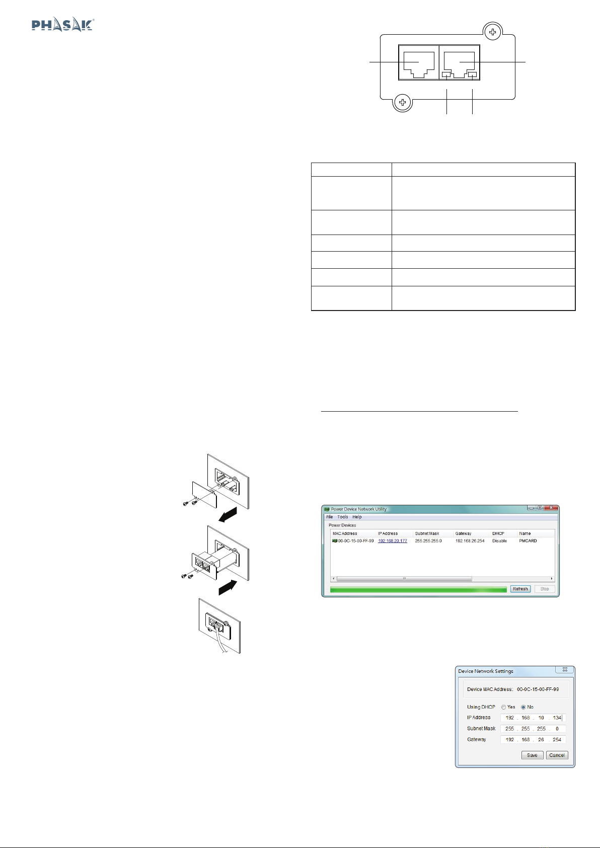
1. Remove the card from the UPS without turning
the UPS off.
2. Remove the jumper from the reset pins. Do not
dispose of the jumper.
3. Insert the card into the expansion port.
4. Wait until the Green LED is flashing (the
frequency of the ON/OFF flashing is once per
second).
5. Remove the card again.
6. Place the jumper back onto the Reset pins.
7. Install card into the expansion port again and
tighten the retaining screws.