Phase II Plus PHT-1800 User manual

ModelNo.PHT‐1800/PHT‐1840&PHT‐1850
OperationManual
21IndustrialAvenue
UpperSaddleRiverNJ07458
(201)962‐7373
www.phase2plus.com

1
1Overview 3
1.1Advantages3
1.2MainApplication&TestingRange.....................................................................3
1.2.1MainApplication...................................................................................................3
1.2.2TestingRange.........................................................................................................3
1.3TechnicalSpecifications........................................................................................3
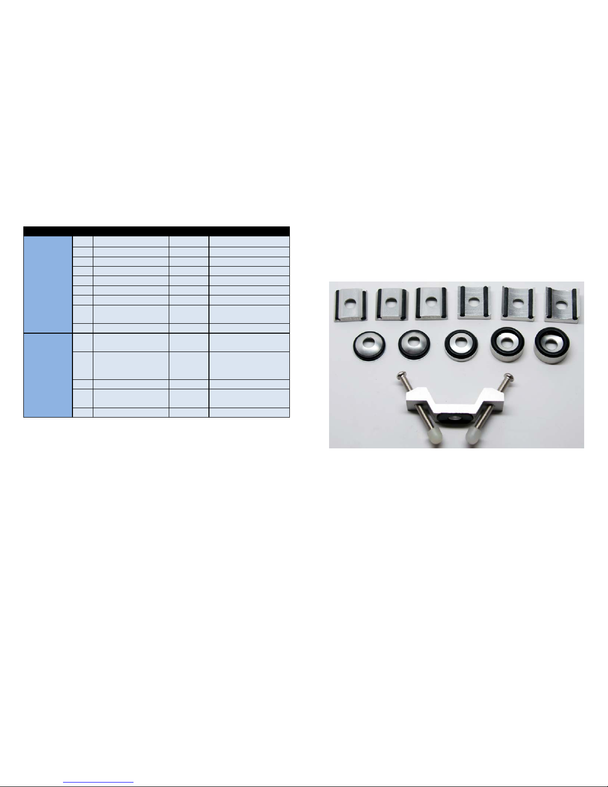
1.4Configuration.............................................................................................................4
1.5WorkingConditions................................................................................................5
2StructureFeature&TestingPrinciple5
2.1StructureFeature......................................................................................................6
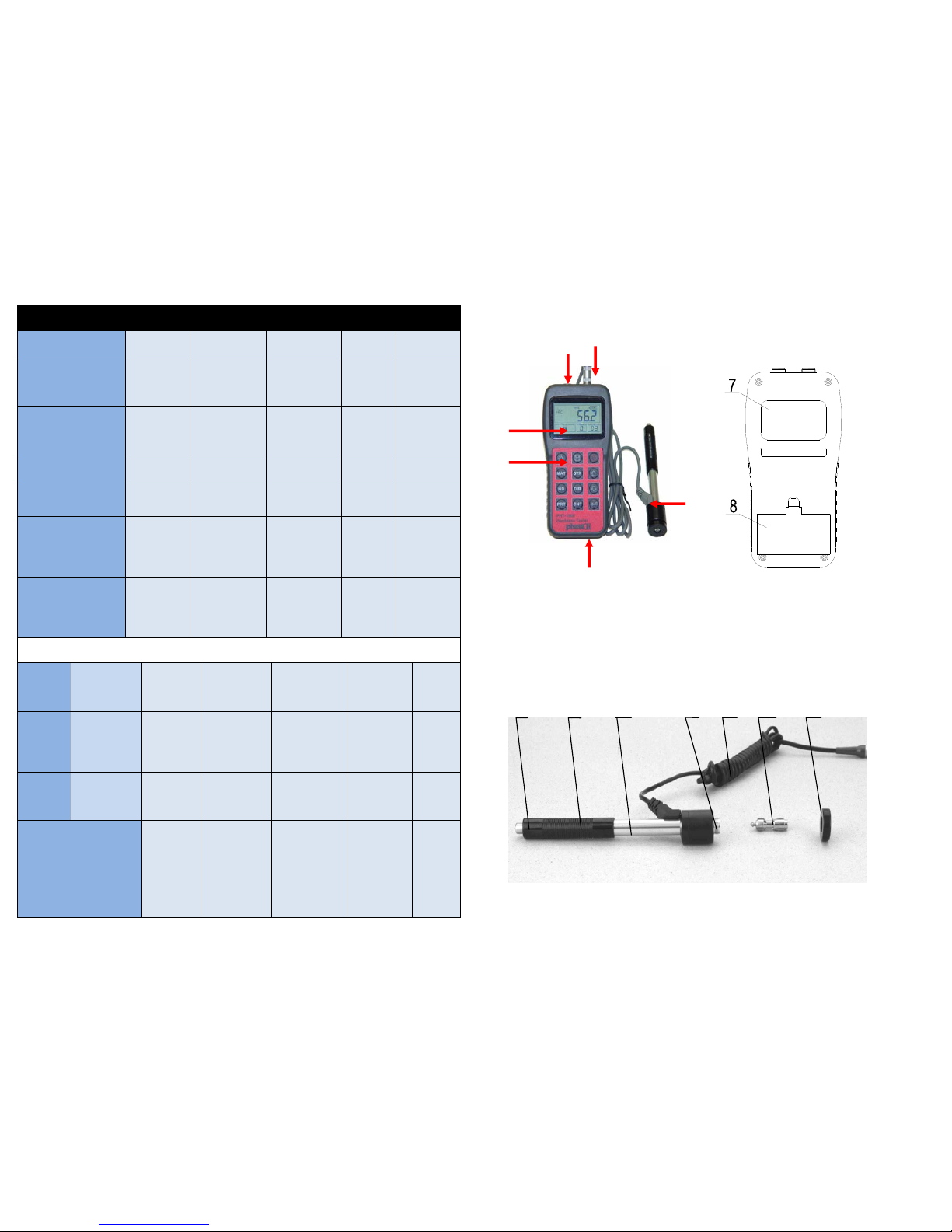
2.1.1DTypeImpactDevice.........................................................................................6
2.1.2DifferentTypesofImpactDevice..................................................................7
2.2MainScreen................................................................................................................7
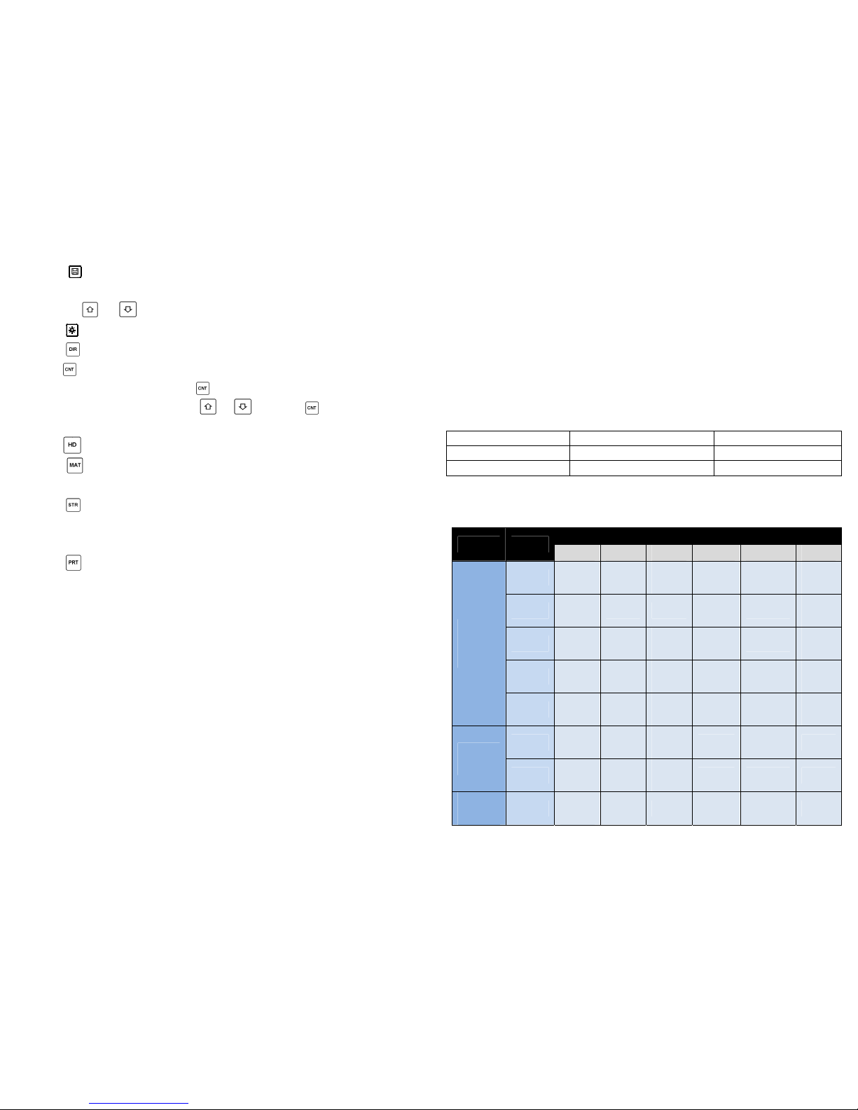
2.3KeypadDefinitions..................................................................................................8
2.4LeebHardnessTestingPrinciple........................................................................9
3Preparation 10
3.1InstrumentPreparationandInspection......................................................10
3.2ImpactDeviceSelection......................................................................................10
3.3PreparationoftheSampleSurface.................................................................11
4TestingProgram 12
4.1Start‐Up......................................................................................................................12
4.2Loading......................................................................................................................12
4.3Localization..............................................................................................................12
4.4Testing........................................................................................................................12
4.5ReadMeasuredValue..........................................................................................13
4.6Notification..............................................................................................................13
5OperationDetail13
5.1PowerOn/Off..........................................................................................................13
5.2MaterialSetting......................................................................................................14
5.3Hardness/Strengthtesting.................................................................................15
5.4ImpactDirectionSetting.....................................................................................15
5.5AverageTimesSetting.........................................................................................15
5.6Datalogging..............................................................................................................15
5.6.1Viewingstoredfile/Group.............................................................................15
5.6.2Clearingselectedfile/Group..........................................................................16
5.7PrintReport.............................................................................................................16
5.8SystemReset...........................................................................................................16
5.9ELBacklight.............................................................................................................17
5.10AutoPowerOff....................................................................................................17
5.11BatteryReplacement.........................................................................................17
5.12ConnectingtoaComputer..............................................................................17
5.13ErrorCodeReference....................................................................................................17
26
Effective:December6,2011
WarrantyPolicy:
Allportableandstationarymaterialtestinginstrumentsmanufacturedfor/by
PhaseIIshallbefreefromdefectsinmaterialandworkmanshipforaperiod
of1to5fullyears(dependinguponmodel)fromdateofpurchase.Partsfound
tobedefectiveshallbereplacedorrepairedatPhaseII’ssolediscretion.
ProductsfoundbyPhaseIItobemisused,abusedorneglectedarenot
coveredunderthiswarranty.Partsnotcoveredbythiswarrantyarenormal
wearandconsumableitemssuchas(butnotlimitedto)impactballs,impact
bodies,diamondindentors,carbideballindentors,impactsprings,cablesand
connectors,batteries,diamondstylus,contactprobes,etc.
Consumable(wearable)itemssuchascablesandprobeshavea90day
warrantyfromdateofpurchase.
Thiswarrantyisexclusiveandinlieuofallotherwarrantieswhetherwritten,
oralorimplied,includinganyimpliedwarrantiesormerchantabilityor
fitnessforaparticularpurpose.InnoeventshallPhaseIIbeliableforany
incidental,specialorconsequentialdamagesofanynature.
ReturnPolicy:
AllPhaseIIproductsmusthaveauthorizationpriortoreturn.
Ifproductisnotacceptableforanyreasonincludingapplicationissuesand
demonstrations,authorizationforreturnmustbeobtainedwithin10daysof
receiptofproduct.Unitmustbeinsamenewconditionitwasreceived.
Failuretodosowillresultinanautomatic15%restockingfee.
Returnsafter30dayswillnotbeaccepted.

25
MainHeadquarters:U.S.A
PhaseIIMachine&Tool,Inc.
21IndustrialAve
UpperSaddleRiver,NJ.07458USA
Tel:(201)962‐7373
Fax:(201)962‐8353
GeneralE‐Mail:info@phase2plus.com
BEIJING,CHINA
PhaseIIMeasuringInstruments(Beijing)Ltd.
Room301,Bldg2QingYuanXiLi,HaidianDistrict,Beijing100192,China
Tel:+86‐10‐59792409
Fax:+86‐10‐59814851
GeneralE‐mail:inf[email protected]
MEXICO
PhaseIIde Mexico
CalleANo.4PromerPiso
Col.SanMarcosAzcapotzalco
C.P02020Mexico
Tel:011‐525‐5538‐39771
Fax:same
GeneralE‐mail:phase2mexico@hotmail.com
VENEZUELA
PhaseIIHerramientasUniversalesEDCM.CA.
Av.FranciscoLazoMartiCC
PlazaSantaMonicaPBLocal
SantaMonica,Caracas1040Venezuela
Tel:212‐690‐28‐21
Fax:212‐693‐29‐16
E‐mail:edcphm@movistar.net
2
6Maintenance&Servicing17
6.1ImpactDeviceMaintenance..............................................................................17
6.2InstrumentMaintenanceProgram.................................................................18
6.3FaultAnalysis&Evaluation...............................................................................18
6.4NoticeofTransportandStorageConditions
APPENDIX.................................................................................................................................18
Table1.............................................................................................................................18
Table2.............................................................................................................................20
Table3.............................................................................................................................21
Table4…………………………………………………………………………………………24

3
1Overview
1.1Advantages
Widemeasuringrange.BasedontheprincipleofLeebhardnesstestingtheory.
CapableofmeasuringLeebhardnessofallmetallicmaterials.
Large screen LCD, showing all functions and parameters. With background
light.
Seven impact devices are available for special application. Automatic
identificationofimpactdeviceuponplugin.
Testatanyangle,evenupsidedown.
DirectdisplayofhardnessscalesHRB,HRC,HV,HB,HS,HL
Large memory could store 100 groups (Relative to average times 1‐32 ) of
information including single measured value, mean value, impactdirection,
impacttimes,materialandhardnessscaleetc.
Batterysymbolshowingthecapacityofthebattery.
Usercalibrationfunction.
OutputviaUSBport.Microprintersupport.
Compactplasticcase,suitableforuseunderpoorworkingconditions
Continuous working period of no less than 100 hours with two alkaline
batteries(AAsize)Autopoweroff.
Outsidedimensions:150×74×32mm
Weight:245g
1.2MainApplication&TestingRange
1.2.1MainApplication
Diecavityofmolds
Bearingsandotherparts
Failureanalysisofpressurevessel,steamgeneratorandotherlargeequipment
Large,hardworkpiece
Testingofinstalledmachineryandpermanentlyassembledparts.
Materialidentificationbaseduponhardnessrange
Rapidtestinginlargerangeandmulti‐measuringareasforlarge‐scale work
piece
1.2.2TestingRange
TestingrangerefertoTable1andTable2intheAppendix.
1.3TechnicalSpecifications
ErrorandrepeatabilityofdisplayedvalueseeTable1‐1below.
24
Windows8InstallationPatch:
ForallPHT‐seriesportablehardnesstesters
1,ConnectthetestertoPCviaUSBcable.Poweruptheinstrument.
2,Runzadig_2.1.2.exe
2,ActivateOptions/ListAllDevices.
Thenselectthe“LeebHardnessTester”item.Selectthe“libusb‐win32(v1.2.6.0)”
option.
3,PressdowntheInstallDriver/ReinstallDriverbutton.Waitforthedriver
installingprocesscomplete.
4,NowtheusbdriverfortheLeebHardnessTesterhasbeensuccessfullyinstalled.
Youcannowrunthedataprosoftwaretocommunicatewiththehardnesstester.
Note:Keeptheinstrumentpoweredupduringdriverinstallationand
connection.
TechSupport:(201)962‐8352

23
PHT‐1800DataOutputSoftwareInstallation:
InsertCDintodriveonyourcomputer
Windowwillpopup
RunAutoRun.exe
Followpromptstoloadprogram,makesureyour
designationdriveissettoC:
Oncecompleteda“DataproforHardnessiconwill
appearondesktop
LaunchtheprogramusingtheDataproforHardness
iconondesktopshortcut
UsingtheUSBcableprovidedinsertroundendto
thehardnesstesterandUSBsidetoyourcomputer
Onthesoftwarescreenselect“Connect”.Itwillask
forwhichCOMportyouareattachedto.SelectCOM
port.
Onceconnectedyoucanviewallsavedmemoryfiles
onscreen.
Therearealsoselectionsfor“Database”and
“Reports”.
4
Table1‐1
No.
Typeof
impact
de v i c e
HardnessvalueofLeeb
standardhardness
block
Errorof
displayed
value
Repeatability
1 D 760±30HLD
530±40HLD
±6HLD
±10HLD
6HLD
10HLD
2 DC 760±30HLDC
530±40HLDC
±6HLDC
±10HLDC
6HLD
10HLD
3 DL 878±30HLDL
736±40HLDL ±12HLDL 12HLDL
4 D+15 766±30HLD+15
544±40HLD+15 ±12HLD+15 12HLD+15
5 G 590±40HLG
500±40HLG ±12HLG 12HLG
6 E 725±30HLE
508±40HLE ±12HLE 12HLE
7 C 822±30HLC
590±40HLC ±12HLC 12HLC
Measuringrange:HLD(170~960)HLD
Measuringdirection:0~360°
HardnessScale:HL、HB、HRB、HRC,HV、HS
Display:4‐DigitLCD
Datamemory:max.100groups(relativetoimpacttimes1‐32)
Workingpower:3V(2AAsizealkalinebatteries)
Continuousworkingperiod:about100hours(Withbacklightoff)
Communicationinterface:USB

5
1.4Configuration
Table1‐2
1.5WorkingConditions
Workingtemperature:0℃~+40℃;
Storagetemperature:‐30℃~+60℃
Relativehumidity:≤90%;
The surrounding environment should be void any vibration, strong magnetic field,
viscousfluids,corrosivemediumandheavydust.
No.ItemQuantityRemarks
Standard
Configuration
1 Mainunit 1
2 Dtypeimpactdevice 1 Withcable
3 Standardtestblock 1
4 Cleaningbrush(I) 1
5 Smallsupportring 1
6 Alkalinebattery 2 AAsize
7 Manual 1
8 Instrument package
case
1
9
Optional
Configuration
11 Cleaningbrush(II) 1 For use with G type
impactdevice
12 Othertypeofimpact
devices and support
rings
RefertoTable3and
Table 4 in the
appendix.
14 Communication
cable
1
16 Printcable 1
22
Optional12pcSupportRingSet
PartNo.PHT1500‐300
Foruseonconvexandconcaveparts

21
Table3
Typeofimpact
de v i c e
DC(D)/DLD+15CGE
Impactingenergy
Massofimpactbody
11mJ
5.5g/7.2g
11mJ
7.8g
2.7mJ
3.0g
90mJ
20.0g
11mJ
5.5g
Testtiphardness:
Dia.Testtip:
Materialoftesttip:
1600HV
3mm
Tungsten
carbide
1600HV
3mm
Tungsten
carbide
1600HV
3mm
Tungsten
carbide
1600HV
5mm
Tungsten
carbide
5000HV
3mm
synthetic
diamond
Impactdevice
diameter:
Impactdevicelength:
Impactdeviceweight:
20mm
86(147)/
75mm50g
20mm
162mm
80g
20mm
141mm
75g
30mm
254mm
250g
20mm
155mm
80g
Max.hardnessof
sample
940HV 940HV 1000HV 650HB 1200HV
Meanroughness
valueofsample
surfaceRa:
1.6μm 1.6μm 0.4μm 6.3μm 1.6μm
Min.weightof
sample:
Measuredirectly
Needsupportfirmly
Needcouplingtightly
>5kg
2~5kg
0.05~2kg
>5kg
2~5kg
0.05~2kg
>1.5kg
0.5~1.5kg
0.02~0.5kg
>15kg
5~15kg
0.5~5kg
>5kg
2~5kg
0.05~2kg
Min.thicknessof
sampleCoupling
tightly
Min.layerthickness
forsurfacehardening
5mm
≥0.8mm
5mm
≥0.8mm
1mm
≥0.2mm
10mm
≥1.2mm
5mm
≥0.8mm
Sizeoftipindentation
Hardness
300HV
Indentation
diameter
Depthof
indentation
0.54mm
24μm
0.54mm
24μm
0.38mm
12μm
1.03mm
53μm
0.54m
m
24μm
Hardness
600HV
Indentation
diameter
Depthof
indentation
0.54mm
17μm
0.54mm
17μm
0.32mm
8μm
0.90mm
41μm
0.54m
m
17μm
Hardness
800HV
Indentation
diameter
Depthof
indentation
0.35mm
10μm
0.35mm
10μm
0.35mm
7μm
‐‐
‐‐
0.35m
m
10μm
Availabletypeofimpact
de v i c e
DC:Test
holeor
hollow
cylindrical
;DL:Test
narrow
grooveor
hole
D+15:
Testgrooves
C:Testsmall,
light,thin
partsand
surfaceof
hardened
layer
G:Test
larg e,
,heavyand
rough
surface
steel
E: Test
super
high
hardnes
s
materia
l
6
2StructureFeature&TestingPrinciple
2.1StructureFeature
1. Mainunit2.Keypad3.LCDdisplay4SocketofUSB
5. Socketofimpactdevice6.Impactdevice7Label8.Batterycover
2.1.1DTypeImpactDevice
1234567
1Releasebutton 2Loadingtube 3Guidetube 4Coilunit
5Connectioncable 6Impactbody 7Supportring
POWER: 2 X 1.5V
HARDNESS GAUGE
0-Steel and Cast Steel
1-Cold Work Too l Steel
2-Stainless Steel
3-Gray Cast Iron
4-Nodular Cast Iron
5-Cast Aluminum Alloys
6-Copper-Zinc Alloys
7-Copper-Aluminum
8-Wrought Copper
9-Wrought Steel
Material Option:
4
1
2
3
5
6

7
2.1.2DifferentTypesofImpactDevice
DCC DD+15DLG
2.2MainScreen
Belowisthemaindisplayscreen:
Hardness Scale
Average
Icon
Direction
Battery Info
Impact Times
Measured
Value
Material No
Memory Icon
20
Table2:LeebtoTensileStrengthConversionChart:
ThisisanApproximationonly!
No.MaterialHLDStrengthσb(MPa)
1 Mildsteel 350~522 374~780
2 High‐Carbonsteel 500~710 737~1670
3 Crsteel 500~730 707~1829
4 Cr‐Vsteel 500~750 704~1980
5 Cr‐Nisteel 500~750 763~2007
6 Cr‐Mosteel 500~738 721~1875
7 Cr‐Ni‐Mosteel 540~738 844~1933
8 Cr‐Mn‐Sisteel 500~750 755~1993
9 Superstrengthsteel 630~800 1180~2652
10 Stainlesssteel 500~710 703~1676

19
HB 85~65
5
HV 85~80
2
Greycast
iron
HRC
HB 93~33
4 92~32
6
HV
Nodular
castiron
HRC
HB 131~3
87 127~3
64
HV
Cast
aluminu
malloys
HB 19~16
4 23~21
0
32~16
8
HRB 23.8~8
4.6 22.7~8
5.0
23.8~8
5.5
BRASS(co
pper‐zinc
alloys)
HB 40~17
3
HRB 13.5~9
5.3
BRONZE(
copper‐
aluminu
m/tin
alloys)
HB 60~29
0
Wrought
copper
alloys
HB 45~31
5
8
InstructionoftheMainDisplayScreen:
Material
:
Thepresentpresettingmaterial.
Impactdirection
:
Thepresentimpactdirection.
Hardnessscale
:
Hardnessscaleofthepresentmeasuredvalue.
Batteryinformation
:
Showsremainingbatterycapacity
Measuredvalue
:
Displaypresentsingletimemeasuredvalue
(
withoutshowing
averageicon
),
ordisplaythepresentmeanvalue(withaverageiconprompting).“‐
HI‐”meansoverconversionvalueormeasurerange.“‐LO‐”meanslowerthan
conversionvalueormeasurerange.
Impacttimes
:
Timesthathavebeentested
AverageIcon
:
Itwillappearwhenshowingthemeanvalueofthemeasuredvalues
afterreachingthepresettingimpacttimes.
MemoryIcon:Itappearswhenoperatingtheinstrumentmemory.
2.3KeypadDefinitions
Table2‐1
Turn
on/off
the EL
backlight
Data Save or Data
Delete
Turn the
instrumen
ton/off
Material
Selection
Hardness/Strengt
hswitch
PlusorUp
Hardnes
s Scale
Selection
Directionchange Minus or
Down
Print
data
ImpactTimesset Data
logging or
Enter

9
Press key to store present group of measured value into memory. This
operationisonlyvalidafterdisplayingthemeanvalue.
Presskey and coulddisplaysinglemeasuredvalue.
Press keycouldswitchonoroffthebackgroundlightofLCD.
Press keytosettheimpactdirection.
Press keytochangetheimpacttimesinonegroup.Theimpacttimesitem
willflash whenfirst pressingthe key, and thentheimpacttimesvaluewill
plus or minus when pressing the or key.Press keyfinallytoexit
fromchangingtheimpacttimesprocess.
Press keytochangethehardnessscale.
Press keytochangethematerial.PresettinghardnessscalerecoverstoHL
automaticallyaftermaterialpresettingchanged.
Press keytoswitchbetweenhardnesstestandstrengthtest.OnlyDandDC
typeofimpactdevicehasthefunctionofstrengthtesting.Sohardnesstestingis
theonlyselectioniftheimpactdeviceisnotDorDCtype.
Press keytoprintoutthemeasuredvaluesaftermeasurement.
2.4LeebHardnessTe s tingPrinciple
Itisdefinedasthequotientofanimpactbody’sreboundvelocityoveritsimpact
velocity, multiplied by 1000. Harder materials produce a higher rebound velocity
than softer materials. For a specific group of material (e.g. steel, aluminum. etc.).
Leebhardnessvaluerepresentsadirectrelationshiptoitshardnessproperties.For
ordinarymetal,conversioncurvesofhardnessHLversusotherstandard sta tic
hardness (HB, HV, HRC, etc.) are available, enabling you to convertHLintoother
hardnessvalues.
18
Releasetheimpactbodyafteruse.
NEVERUSELUBRICANTORCLEANERSONIMPACTDEVICE!
6.2InstrumentMaintenanceProgram
WhentestingintheRockwellChardnessscaleyourerroramountshouldnot
exceed2RockwellCpoints.Changingthesphericaltesttiporimpactbody
shouldbeconsidered.
WarrantywillbeVOIDifunithasbeendismantledbysomeoneother
thananauthorizedrepairperson
6.3FaultAnalysis&Evaluation
FaultAppearanceFaultAnalysisRepairmethod
Failuretopoweron LowordeadBattery Replacethebatteries
Nomeasuredvalue Impactdevicecablefailure Replacethecable
APPENDIX
Table1
MaterialMethodImpactde v i c e
D/DC D+15 C G E DL
Steeland
caststeel
HRC 20~68.
5
19.3~6
7.9
20.0~6
9.5 22.4~70.
7
20.6~6
8.2
HRB 38.4~9
9.6 47.7~9
9.9 37.0~9
9.9
HB 127~6
51
80~63
8
80~68
3
90~64
6 83~663 81~64
6
HV 83~97
6
80~93
7
80~99
6 84~1042 80~95
0
HS 32.2~9
9.5
33.3~9
9.3
31.8~1
02.1 35.8~10
2.6
30.6~9
6.8
Coldwork
toolsteel
HRC 20.4~6
7.1
19.8~6
8.2
20.7~6
8.2 22.6~70.
2
HV 80~89
8
80~93
5
100~9
41 82~1009
Stainless
steel HRB 46.5~1
01.7

17
5.9ELBacklight
WiththeELbackgroundlight,itisconvenienttoworkindarkerconditions.
Presskey toswitchonorswitchoffthebackgroundlightatanymomentasyou
needafterpoweron.SincetheELlightwillconsumemorepower,turnonitonly
whennecessary.
5.10AutoPowerOff
The instrument features an auto power off function designed to conserve
battery life. If the tool is idle (neither measuring nor any key operation) for 5
minutes,itwillturnitselfoff.Beforepoweringoff,theLCDdisplayoftheinstrument
willcontinueflashingfor20seconds.Topreventtheunitfrompoweringoffyoucan
pressanybuttonExcept Power.
Whenthevoltageofthebatterygetstoolow,thedisplaywillshow<E00>,then
poweroffautomatically.
5.11BatteryReplacement
The PHT‐1800 uses standard AA batteries. After several hours of usage, the
battery symbol on the screen will begin to show less dark tabs which is shown
as . When the batteries are drained, the battery symbol will be shown as
andwillbegintoflash.Whenthisoccurs,thebatteriesshouldbereplaced.
Payattentiontothepolarityofthebatteries!
Pleaseproperlydisposeofusedbatteriesaccordingly.
5.12ConnectingtoaComputer
TheInstrumentisequippedwithaUSBserialport.Usingtheoutputcablethe
gauge has the ability to connect to a computer, or external storage device.
Measurementdatastoredinthememoryofthegaugecanbetransferred to the
computerthroughtheUSBport.
5.13ErrorCodeReference
ErrorCodeExplanationErrorCodeExplanation
E00 ReplaceBattery E05 Can’tprint
E01 Valueoutofrange E06
E02 Measurement
notfinished
E07
E03 Dataalreadysaved E08
E04 Nomemorydata E09
6Maintenance&Servicing
6.1ImpactDeviceMaintenance
Aftertheimpactdevicehasbeenusedfor1000‐‐2000times,pleaseusethe
nylon brush provided to clean the guide tube and impact body. When
cleaningtheguidetube,unscrewthesupportringfirst,thentake out the
impactbody, spiral the nylonbrushincounter‐clockwisedirectionintothe
bottom of guide tube and repeat a few times to remove any dust or small
chipsinsidethetube.Theninstalltheimpactbodyandsupportringagain.
10
3Preparation
3.1InstrumentPreparationandInspection
Calibrationoftheinstrumentisperformedbyusingastandardcalibratedtestblock.
The error and repeatability of displayed value should be within+/‐6HLpoints(D
device)Theinstrumentandimpactdevicemustbecalibratedusingastandard
hardnessblockpriortofirstusageorhavingresettheinstrumentsystem.
Press key,whilesimultaneouslypressingdownthe keytopoweronthesystem.
Thecalibrationscreenshowsasbelow.
Take5testsonyourstandard
hardness block. The display will
showtheaveragemeasuredvalue
after measuring 5 times. Press
keytochangetoits
nominalvaluetomatchthevalue
shownonyourtestblock.
Press key to confirm the
calibration.Orpressthe keyto
cancelthecalibration.
Rangeofadjustment:±30HL.
Themeasurementparameters,includingthematerialsetting,thehardnessscaleand
theimpactdirectioncan’tbechangedduringcalibration.
3.2ImpactDeviceSelection
RefertoAppendixTable1andTable3forselectionofimpactde v i c e .
Note:For Verification, Take 5 tests around the test block and get
your average. This average value should be within the acceptable
tolerance of the test block value. If this value exceeds the
allowable tolerance of the test block, a calibration should be
performed. See above.

11
3.3PreparationoftheSampleSurface
Preparation for sample surface should conform to the relative requirement in
AppendixTable3.
Test surfaces should be at or close to room temperature for optimal
performance
To eliminate hardness errors resulting from the roughness of a sample’s
surfacewhenusingimpactdeviceD,DCorD+15,thetestsurfaceshouldbe
polisheduntilitsroughnessRaisnomorethan2m.PHASEIISRG‐2000
handheldsurfaceroughnesstesteroranyothersuitableinstrumentmaybe
used to measure the surface roughness of the sample material. The test
surfaceshouldbecleanandfreefromoilstains.
Supportoftestsample.Supportisnotnecessaryforheavysample s . L i g h t e r
weightpartsmustbesetontheflat,smoothsurfaceofalargermassmetal
object.Thesamplemustbecompletelystationaryandwithoutany gaps
betweenthetwoparts.
Curvedsurface:Thebesttestingsurfaceofsampleisflat.When the
curvatureradiusRofthesurfacetobetestedissmallerthan30mm(D,DC,
D+15,C,EandDLtypeofimpactdevice)andsmallerthan50mm(Gtypeof
impact device), the small supportring or the shaped support ringsshould
bechosen.
Thesampleshouldhaveenoughmass.Minimumthicknessofsampleshould
conformtoTable3.
Forthesamplewithhardenedlayeronsurface,thedepthofharde n e d la y e r
shouldconformtoTable3.
Coupling.Light‐weightsamplemustbefirmlycoupledtoapartwith much
largermass.Bothcoupledsurfacemustbeflatandsmooth.Theimpact
directionmustbeverticaltothecoupledsurface.Whenthesampleisabigplate,
orlongrod,itcanbedeformedandbecomeunstable,eventhoughitsweightand
thicknessiswithinallowableranges,andaccordingly,thetestvaluemaynotbe
accurate.Sothesampleshouldbereinforcedorsupportedatitsback.
16
4) Usethe keyandthe keytovieweachsinglemeasureddatainthatgroup
whileviewingdetails.
5) Pressthe keytoreturntopreviousscreenatanytimeduringdatalogging.
5.6.2Deletingselectedfile/Group
Theusermayrequiredeletingafilefromtheinstrumentmemory.Theprocedure
isoutlinedinthefollowingsteps.
1) Press the keytoactivatethedataloggingfunction.Thememoryiconwill
appear.Itwilldisplaythecurrentfilename,thetestparameterofthegroupdata
and the mean value of the group. If there is no data in the memory, it will
display:<E04>,whichmeansnomemorydata,andthenreturnback.
2) Usethe keyandthe keytoscrolltothefilethatwillbedeleted.
3) Press the keyonthedesiredfile.Itwillautomaticallydeletethefile, and
display“‐DEL”.
4) Press the key,atanytime,toexitthedataloggingfunctionandreturnto
measurementmode.
Note
:
Donotshutdowntheinstrumentwhilede leting da t a. Itcouldleadtoloss
ofallda t a ifshutdownwhiledele ti n g.
5.7PrintReport
Attheendoftheinspectionprocess,orendoftheday,theusermayrequirethe
readingsbeprinted.
Before printing, please insert one connection plug of the printcableintothe
socketontheupperleftsideofthemainbody,andinserttheother plug into the
communication socket of your PC. You can print out the measurement result
immediatelyaftereachtestingprocess,byeasilypressingthe key.
Ifyouwanttoprintthedatastoredintheinstrumentmemory,thenfollowthese
steps:
1. Press the keytoactivatethedataloggingfunction.Thememoryiconwill
appear.
2. Usethe keyandthe keytoselectthedesiredfile.
3. Pressthe keytoprinttheselectedfile.Thisoperationwillsendallthedatain
currentfiletotheminiprinterviaRS232portandprintthemout.
4. Pressthe keytoexitthedataloggingfunctionsandreturntomeasurement
mode.
5.8SystemReset
Press down the keywhilepoweringontheinstrumentwillrestore
factorydefaults.Theonlytimethismightpossiblyhelpfulisifoneoftheparameters
inthegaugeweresomehowcorrupted.

15
0 Mildsteel 5 Cr‐Mosteel
1 Highcarbonsteel 6 Cr‐Ni‐Mosteel
2 Crsteel 7 Cr‐Mn‐Sisteel
3 Cr‐Vsteel 8 Superstrengthsteel
4 Cr‐Nisteel 9 Stainlesssteel
5.3Hardness/Strengthtesting
Press keytoswitchbetweenhardnesstestingandstrengthtesting(бb).
Note:OnlyDandDCtypeofimpactdevic e hasthefunctionofstrengthtesting.So
hardnesstestingistheonlyselectioniftheimpactdevic e isnotDorDCtype.
In hardness testing, Press key to change the hardness scale. The
supportedhardnessscaleincludes:HL,HV,HB,HRC,HSandHRB.
Note
:
Thisdisplaysthevalidhardnessscaleforthepresentselectedimpact
devi c eandmaterial.Itwouldnotdisplaythehardnessscalewhichisnot
valid.
Pleaseselectmaterialfirst,thenselecthardnessscale.
PresettinghardnessscalerecoverstoHLautomaticallyafterpresetting
materialischanged.
5.4ImpactDirectionSetting
Pressthe keytomovetotheimpactdirectionthatyouwillworkin.
5.5AverageTimesSetting
Youcouldmodifyaveragetimeswithintherangeof1to32asfollowing:
1) Press keyintestingstate.Theimpacttimesitemwillbegintoflash;
2) Press or keytosettheaveragetimestothenumberyouwant.
3) Press keyfinallytoexitfromtheoperation.
5.6Datalogging
Atmostonehundredfiles(F00‐F99,onegroupasonefile)canbestoredinside
the gauge. By simply pressing the keyafteranewmeasurementfinishes‐the
screenshowingthe“AVE”icon,themeasuredhardness/strengthgroupvalueswillbe
savedtomemory.Thenewsavedfileisappendedasthelastfileofthememory.This
functionprovidestheuserwiththeabilitytoview/deleteafile/group previously
savedinmemory.
5.6.1Viewingstoredfile/Group
Toviewthememorydata,followthesteps:
1) Press the keytoactivatethedataloggingfunction.Thememoryiconwill
appear.Itwilldisplaythecurrentfilename,thetestparameterofthegroupdata
andthemeanvalueofthegroup.Ifthereisnodatainthememory,itwilldisplay:
<E04>,whichmeansnomemorydata,andthenreturnback.
2) Usethe keyandthe keytoselectthedesiredfiletoview.
3) Pressthe keytoseedetailsofthatgroupdata.
12
AVOIDanyobjectthathasastrongMagneticForce.
4TestingProgram
4.1Start‐Up
Inserttheplugoftheimpactdeviceintothesocketofimpactde v i c e o n t h e
instrument.
Pressthe keytopowertheuniton.Theinstrumentreadyfortesting.
4.2Loading
Pushingtheloading‐tubedownwardsuntilcontactisfelt.Thenallow it to slowly
returntothestartingpositionorusingothermethodlockingtheimpactbody.
4.3Placement
Press the impact device supporting ring firmly on the surface ofthe sample, the
impactdirectionshouldbeverticaltothetestingsurface.
4.4Testing
Pressthereleasebuttonontheupsideoftheimpactdevicetotest.Thesample,
theimpactdeviceaswellastheoperatorareallrequiredtobestable.Theaction
directionshouldpasstheaxisoftheimpactdevice.
Eachmeasuredareaofthesampleusuallyneed3to5timesoftestingoperation
toobtainanaverage.Theresultdatadispersionshouldnotmore than mean
value±15HL。
Thedistance betweenanytwo impact points or fromthecenterofanyimpact
pointtotheedgeoftestingsampleshouldconformtotheregulationofTable4‐1.

13
Table4‐1
Typeof
Impact
Device
Distanceofcenterofthe
twoindentations
Distanceofcenterofthe
indentationtosample
edge
Notlessthan(mm) Notlessthan(mm)
D、DC 3 5
DL 3 5
D+15 3 5
G 4 8
C 2 4
4.5ReadMeasuredValue
After each impact (test), the LCD will display the current measured value,
impacttimesplusoneandabeepwillalertyouifthemeasuredvalueisnotwithin
thevalidrange.Theunitwillbeepwhenreachingthepresetfor average impact
timesandimmediatelydisplaytheaverageofyourtests.
4.6Notification
ReplacingtheimpactdevicemustbedonewhileunitisPoweredoff.
Youcanonlysavedataaftertheaveragehasbeenobtained.
OnlytypeDandtypeDCofimpactdevicehavethefunctionoftensilestrength
testoption.Youcannotchangethesettingtostrengthtestingwhenusingother
typesofimpactdevice.
Not all materials canconverttoallhardness scalevalue.Thehardness scale is
resettoHLautomaticallyafterchangingthematerial.Soselectmaterialpriorto
changingthehardnessscale.
5OperationDetail
5.1PowerOn/Off
PlugintheimpactdeviceFIRST.Press topowerontheinstrument.Theunit
will automatically detect the type of the impact device during power up, and will
displaysavedsettinginformationonthescreen
14
The instrument can be turned off by pressing the key.Thehardnesstester
hasmemorythatretainsallofitssettingsevenwhenthepowerisoff.
5.2MaterialSetting
Press keytochangethematerialtotheoneyouwanttopreset.Hardness
scale defaults to HL automatically after material presetting changed. Please select
materialfirst,thenselecthardnessscale.
Youcanselectyourmaterialamongthefollowingselections:Steel and Cast
Steel、Cold Work Tool Steel、Stainless Steel、Gray Cast Iron、Nodular Cast
Iron、Cast Aluminum Alloys、Copper‐Zinc Alloys、Copper‐Aluminum Alloy and
Wrought Copper. The relationship between the material number displayed on the
instrumentscreenandthematerialisasfollows:
Table5‐1
Material
No.
MaterialMaterialNo.Material
0 Steelandcaststeel 5 Castaluminiumalloys
1 Coldworktoolsteel 6 Copper‐Zincalloys
2 Stainlesssteel 7 Copper–Aluminiumalloys
3 Graycastiron 8 Wroughtcopper
4 Nodularcastiron
Instrengthtesting,thefollowingmaterialsares e le c ta b le : MildSteel、High‐
CarbonSteel、CrSteel、Cr‐VSteel、Cr‐NiSteel、Cr‐MoSteel、Cr‐Ni‐Mo
Steel、Cr‐Mn‐SiSteel、SuperStrengthSteelandStainlessSteel.The
relationshipbetweenthematerialnumberdisplayedontheinstrumentscreen
andthematerialisasfollows:
Table5‐2
MaterialNoMaterialMaterialNoMaterial
This manual suits for next models
2
Table of contents
Popular Test Equipment manuals by other brands

DigiTrak
DigiTrak Falcon F2 Operator's manual

Elektro-Automatik
Elektro-Automatik EL 9000 B 15U Series operating manual

Radio Shack
Radio Shack Micronta 22-204 A operating instructions

Lutron Electronics
Lutron Electronics LL-INTMOUNT Integration guide

Aeroflex
Aeroflex ATC-1400A-2 Maintenance manual

SEFRAM
SEFRAM 52 instruction manual