PhaseOne PAS Pana User manual

Version: 1.1
Date: November 10, 2023
PAS Pana
Operation Guide

PAS Pana Operation Guide
Page 2 of
50
Legal Notice
The company disclaims all liability and warranties in relation to this manual, including warranty of merchantability, fitness for
particular purpose and accuracy, and may amend it without further notice.
Trademarks
All trademarks or registered trademarks are the property of their respective owners.
Contact Support
You can contact Phase One Technical Support directly by creating a support case at
https://support.phaseone.com/
Visit https://geospatial.phaseone.com/ for additional information.
Copyright © 2023 Phase One. All Rights Reserved.
Doc No. 80113000 Rev 1.1 PAS Pana Operation Guide 10/11/2023

PAS Pana Operation Guide
Table of Contents
Page 3 of
50
Table of Contents
1Introduction ................................................................................................................................................................................... 5
1.1 Scope ................................................................................................................................................................................. 5
1.2 Applicable Documents.......................................................................................................................................................5
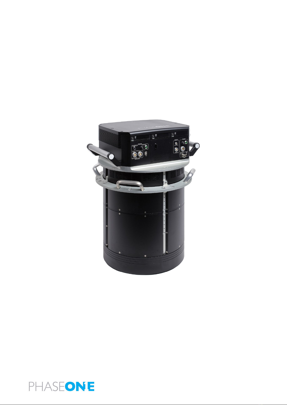
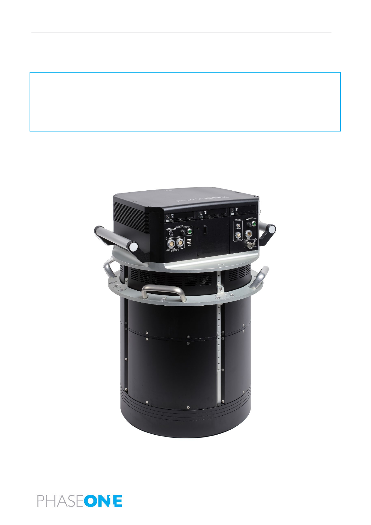
2PAS Pana Overview ........................................................................................................................................................................ 6
2.1 Hardware ........................................................................................................................................................................... 7
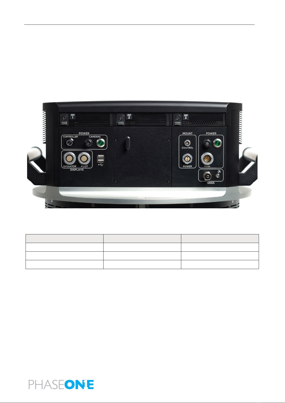
2.1.1 PAS Pana Controller ...........................................................................................................................................7
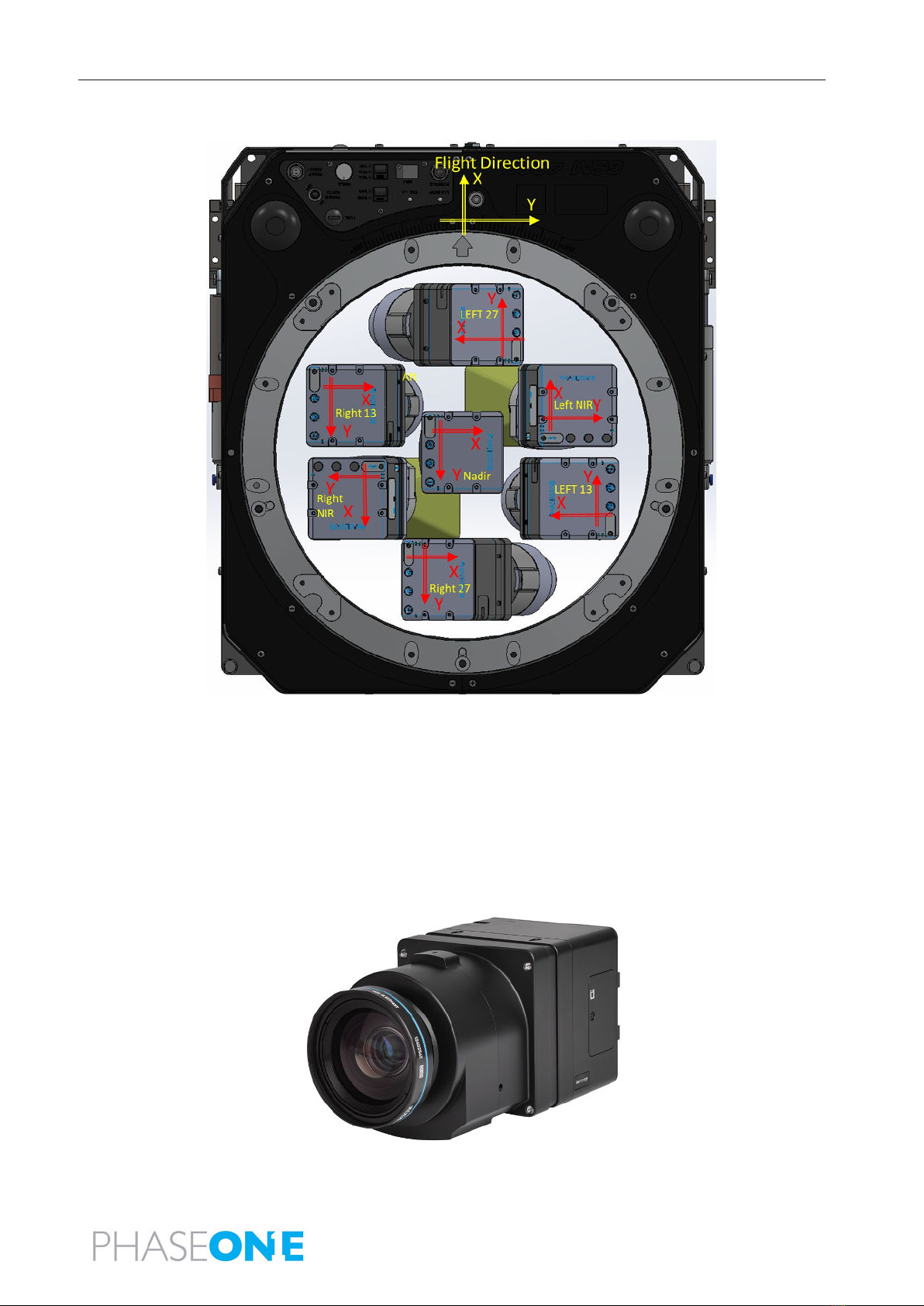
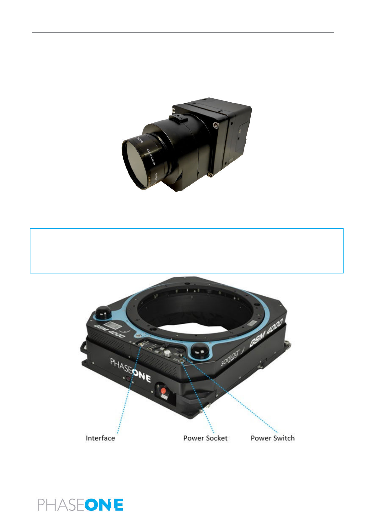
2.1.2 Cameras .............................................................................................................................................................7
2.1.3 SOMAG GSM 4000 Mount ................................................................................................................................. 9
2.1.4 Applanix GNSS/IMU .........................................................................................................................................10
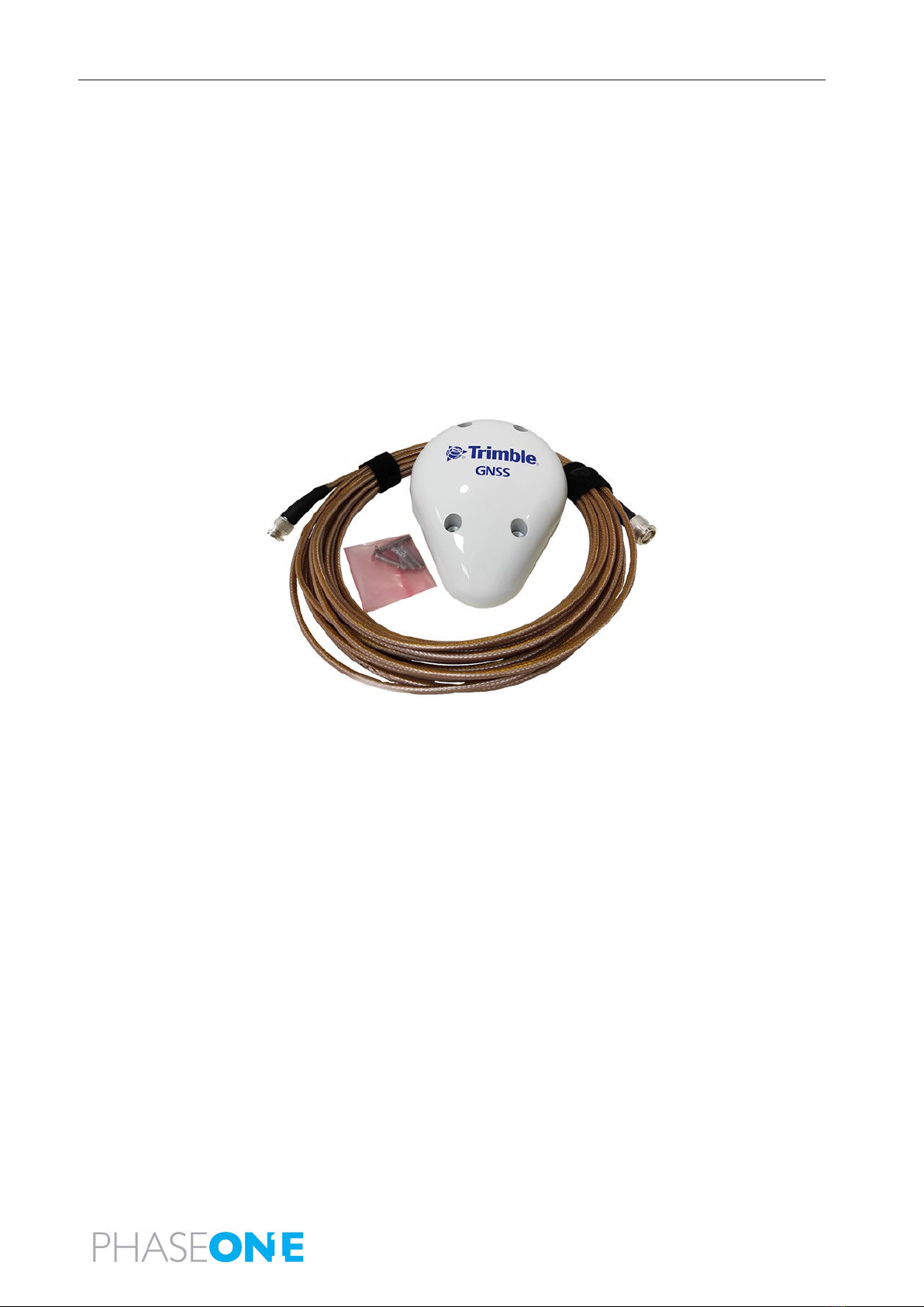
2.1.5 Trimble AV39 Antenna ..................................................................................................................................... 10
2.1.6 Monitor Kit ....................................................................................................................................................... 10
2.2 Software .......................................................................................................................................................................... 12
2.2.1 iX Flight Pro ...................................................................................................................................................... 12
2.2.2 Licensing...........................................................................................................................................................12
2.3 PAS Pana Dataflow...........................................................................................................................................................13
3Unboxing the PAS Pana................................................................................................................................................................ 14
3.1 Product Identification ...................................................................................................................................................... 14
4PAS Pana Height Adjustment and Testing in the Office ...............................................................................................................15
4.1 Adjusting the PAS Pana Mount Ring Height.....................................................................................................................16
4.1.1 Adjusting the PAS Pana System Case Mount Plate Height...............................................................................18
4.2 Connecting a PAS Pana in the Office................................................................................................................................ 19
4.2.1 Connecting PAS Pana Components ..................................................................................................................19
4.3 Powering the PAS Pana and Mount in the Office ............................................................................................................21
4.4 Configuring the PAS Pana ................................................................................................................................................ 22
4.4.1 Changing Monitor Orientation .........................................................................................................................22
4.4.2 Changing the Mouse Pointer Color ..................................................................................................................24
4.4.3 Configuring Touch Monitors ............................................................................................................................25
4.4.4 Check Camera Firmware for Updates ..............................................................................................................27
4.4.5 Configuring GNSS/IMU Parameters .................................................................................................................27
4.4.6 Configuring Screen Recorder Pro .....................................................................................................................27
4.4.7 Configuring iX Flight Pro...................................................................................................................................29
4.4.8 Checking the PAS Pana.....................................................................................................................................29
4.4.9 Configuring Lever Arms....................................................................................................................................29
4.5 Disconnecting the PAS Pana in the Office........................................................................................................................ 30
5Installing the PAS Pana in the Aircraft.......................................................................................................................................... 31
5.1 Required Tools................................................................................................................................................................. 31

PAS Pana Operation Guide
Table of Contents
Page 4 of
50
5.2 Installing the Trimble AV39 Antenna............................................................................................................................... 31
5.3 Securing the Interface Plate to the Aircraft ..................................................................................................................... 31
5.4 Securing the Mount to the Interface Plate ......................................................................................................................32
5.5 Installing the PAS Pana on the Mount .............................................................................................................................33
5.6 Installing the Pilot Monitor .............................................................................................................................................. 34
5.7 Installing the Operator Monitor ...................................................................................................................................... 34
5.8 Connecting a PAS Pana and Mount in the Aircraft ..........................................................................................................35
5.8.1 Connecting PAS Pana Components ..................................................................................................................35
5.8.2 Powering the PAS Pana and Mount in the Aircraft ..........................................................................................35
5.9 PAS Pana Installed in Aircraft........................................................................................................................................... 36
6Recommended Flight Operation Procedure.................................................................................................................................37
7Post Flight Operations.................................................................................................................................................................. 38
8Disassembling the PAS Pana ........................................................................................................................................................ 39
9Troubleshooting ........................................................................................................................................................................... 40
Appendix A Technical Data ............................................................................................................................................................. 41
A.1 PAS Pana Weight .............................................................................................................................................................41
A.2 Power Specifications........................................................................................................................................................ 41
A.2.1 Power Requirements........................................................................................................................................ 41
A.2.2 Power Consumption......................................................................................................................................... 41
Appendix B Data Storage Management ......................................................................................................................................... 42
B.1 Disk Management............................................................................................................................................................ 42
B.2 Locking the Carrier........................................................................................................................................................... 42
B.3 Removing the SSD Drive Carrier ...................................................................................................................................... 43
B.4 Inserting the SSD Drive Carrier ........................................................................................................................................44
B.5 Replacing SSD Drives........................................................................................................................................................ 44
Appendix C Connecting the PAS Pana – Operator Monitor Cable to the Monitor ........................................................................46
Appendix D Declarations of Conformity .........................................................................................................................................48
D.1 PAS Pana Controller......................................................................................................................................................... 48
D.2 iXM-RS150F Camera ........................................................................................................................................................ 49
D.3 iXM-RS150F Achromatic Camera ..................................................................................................................................... 50

PAS Pana Operation Guide
1. Introduction
Page 5 of
50
1Introduction
1.1 Scope
This manual describes how to install and use the PAS Pana as follows:
•Section 2 - PAS Pana Overview
•Section 3 - Unboxing the PAS Pana
•Section 4 - PAS Pana Height Adjustment and Testing in the Office
•Section 5 - Installing the PAS Pana in the Aircraft
•Section 6 - Recommended Flight Operation Procedure
•Section 7 - Post Flight Operations
•Section 8 - Disassembling the
•Section 9 - Troubleshooting
•Appendix A - Technical Data
•Appendix B - Data Storage Management
•Appendix C - Connecting the PAS Pana – Operator Monitor Cable to the Monitor
•Appendix D - Declarations of Conformity
1.2 Applicable Documents
Item
Manual
Applanix GNSS/IMU
GNSS Configuration Guide for PAS Systems
Phase One iX Flight Pro
iX Flight Pro Operation Guide
Phase One iX Process
iX Process Operation Guide
Somag GSM 4000 Mount
SOMAG GSM 4000 Manual
Trimble AV39 Antenna
Trimble AV39 Antenna Datasheet

PAS Pana Operation Guide
2. PAS Pana Overview
Page 6 of
50
2PAS Pana Overview
Note
•There are no user serviceable parts inside the PAS Pana or PAS Pana Controller. All warranties are void if access panels are
opened or cables not supplied by Phase One are connected, unless specifically instructed by Phase One personnel.
•Installation of the PAS Pana in an aircraft must be performed by certified personnel while following the relevant Civil Aviation
Authority regulations in the country of aircraft registration and operation. A Supplemental Type Certificate or Minor Change
may be required.
PAS Pana is a derivative of the PAS Pod family of products. The PAS Pana utilizes five RGB cameras and two NIR cameras to
maximize swath coverage.
PAS Pana provides 48,000 pixels across line of flight and 10,000 pixels along line of flight. With its high frame rate and large
coverage, high project efficiency is attained.

PAS Pana Operation Guide
2. PAS Pana Overview
Page 7 of
50
2.1 Hardware
2.1.1 PAS Pana Controller
The PAS Pana Controller is the communication center, and data storage for the PAS. Based on Microsoft Windows 10, it is
responsible for controlling power and communication for all ancillary systems.
A preconfigured precision GNSS-Inertial (AP+ AV) is integrated in the PAS Pana Controller.
The PAS Pana Controller contains three SSD drive bay frames that contain removable carriers with SATA SSDs that store the
captured images. Each carrier holds two 4 TB SSDs.
2.1.2 Cameras
The PAS Pana camera configuration is as follows:
Camera Location
iXM-RS150F RGB
iXM-RS150F Achromatic
Nadir
1 camera
-
Right
2 cameras
1 camera
Left
2 cameras
1 camera

PAS Pana Operation Guide
2. PAS Pana Overview
Page 8 of
50
The following figure shows the orientation of the PAS Pana cameras.
2.1.2.1 iXM-RS150F Camera
The iXM-RS150F camera is equipped with a full-frame sensor (14,204 x 10,652 pixels), using 3.76-micron pixel technology that
enables high ground resolution from high flight altitudes. It provides large aerial coverage resulting in higher aerial survey
productivity.
The PAS Pana iXM-150F cameras are fitted with RS150 mm lenses.
Designed and built for aerial photography by Rodenstock and Schneider-Kreuznach, the lenses are factory calibrated for infinity
focus and equipped with a central leaf shutter with a speed to up to 1/2500 sec.

PAS Pana Operation Guide
2. PAS Pana Overview
Page 9 of
50
2.1.2.2 iXM-RS150F Achromatic Camera
The iXM-RS150F achromatic camera provides NIR data in the spectral range of 720 nm-1000 nm.
The PAS Pana iXM-150F achromatic cameras are fitted with RS70 mm lens.
Post processing this data in combination with the iXM-RS150F RGB data allows output imagery as IRG/RGBi CIR products or NDVI.
2.1.3 SOMAG GSM 4000 Mount
The PAS Pana is mounted on a SOMAG GSM 4000 mount, a hydraulic gimbal containing four cylinders and two servo pumps.
Note
•PAS Pana can only operate with SOMAG GSM 4000 mounts with serial numbers 090236 and higher, or with earlier mounts that
were refurbished by SOMAG to the dual communication port configuration.
•
If you are providing the SOMAG GSM 4000, you also need to provide Vibration Damping Ring P/N 112300-228-02/04.

PAS Pana Operation Guide
2. PAS Pana Overview
Page 10 of
50
2.1.4 Applanix GNSS/IMU
The Applanix GNSS/IMU contains a precision GNSS receiver and inertial sensor components, logging capability, and interfaces for
cameras and flight management systems.
Data such as geographic position (latitude, longitude and altitude), velocity, acceleration, angular rate, orientation (roll and pitch),
ground track and performance metrics are available in real-time and through post-processing.
The Applanix GNSS/IMU is comprised of the Applanix AP+ card located in the PAS Pana Controller and the IMU-57.
The Applanix GNSS is configured and managed via a browser-based application supported by the Applanix AP+ card. You can access
the application through the shortcut on the PAS Pana Controller software taskbar.
2.1.5 Trimble AV39 Antenna
The Trimble AV39 antenna is a lightweight, TSO certified antenna that provides centimeter precision with superior phase center
repeatability. The antenna is connected to the PAS Pana Controller via a coaxial cable supplied with the antenna.
2.1.6 Monitor Kit
The monitor kit allows full control and flight feedback of the PAS Pana and includes the following:
•pilot monitor
•operator monitor

PAS Pana Operation Guide
2. PAS Pana Overview
Page 11 of
50
2.1.6.1 Pilot Monitor
The 7” pilot monitor provides all flight information from iX Flight Pro (see section 2.2.1 - iX Flight Pro), ensuring that the pilot has all
required information to conduct a successful survey mission. The touch screen allows the pilot to perform several quick-access
operations in iX Flight Pro (map display, zoom, line selection).
2.1.6.2 Operator Monitor
The 15.6” operator monitor provides all required information from iX Flight Pro, ensuring the operator can control all aspects of the
flight, including run selection, camera control, and data management using the touch screen.
The operator is installed with the cables leading to the lower part of the monitor. The monitor orientation is then set in Microsoft
Windows to flipped landscape.
Note
You can install a 21” screen for the operator instead of the 15.6” screen. For details, contact Phase One.

PAS Pana Operation Guide
2. PAS Pana Overview
Page 12 of
50
2.2 Software
2.2.1 iX Flight Pro
iX Flight Pro uses iX Plan data to manage and guide the precise execution of aero-photography flight. Using the pilot and operator
monitors, the pilot can easily maintain a precise trajectory by following altitude and localizer instructions, while the operator
manages the flight, controls the order of passes, tags images and start/stops image collection. iX Flight Pro is pre-installed in PAS
Pana Controller.
For detailed information on using iX Flight Pro, see the iX Flight Pro Operation Guide provided with your PAS Pana.
Note
To process captured images, use iX Process available from Phase One.
2.2.2 Licensing
The iX Flight Pro software license is preinstalled in the PAS Pana Controller.

PAS Pana Operation Guide
2. PAS Pana Overview
Page 13 of
50
2.3 PAS Pana Dataflow
The following table details the dataflow for the PAS Pana.
Dataflow for the PAS Pana
Cable
Signal/Data
From
To
Protocol
Description
Camera Trigger
& MEP
Camera trigger
PAS Pana
Controller
Camera
Analog I/O
discrete
iX Flight Pro (in PAS Pana Controller)
calculates when to capture an image
(based on NMEA/GSOF data received
from Applanix AP+) and issues a trigger.
MEP (Mid
Exposure Pulse)
Camera
PAS Pana
Controller-AP+
Discrete
Camera sends an event input to the PAS
Pana Controller when the image is
captured.
Event data
PAS Pana
Controller
Camera
RS-232
Applanix AP+ (in PAS Pana Controller)
sends event metadata to camera for
image metadata.
Mount Control
Start/Stop pass
IMU angle data
PAS Pana
Controller
SOMAG
GSM 4000 mount
RS-232
•iX Flight Pro (in PAS Pana Controller)
sends angle data to SOMAG mount
for stabilization enhancement.
•iX Flight Pro (in PAS Pana Controller)
calculates Start of Line and before
reached, sends "Stab" command to
SOMAG mount.
•iX Flight Pro (in PAS Pana Controller)
calculates End of Line and after
reached, sends "Manual" command
to SOMAG mount.
GIM01
SOMAG
GSM 4000
mount
PAS Pana
Controller AP+
RS-232
SOMAG mount platform sends GIM01
message with platform angles to the
Applanix AP+ (in PAS Pana Controller) for
registration in T04 files.
USB3 (for each
camera)
Images
Camera
PAS Pana
Controller
USB
Images taken by camera transferred to
PAS Pana Controller SSD.

PAS Pana Operation Guide
3. Unboxing the PAS Pana
Page 14 of
50
3Unboxing the PAS Pana
PAS Pana is delivered in two cases:
•system case
•equipment case.
Verify that all parts were supplied according to the specific packing list for your PAS Pana.
3.1 Product Identification
To enable support for your PAS Pana, you must identify and record the model and serial numbers for each of the following
components:
•PAS Pana: serial number is located on a label on the PAS Pana Controller rear panel.
Note
You can view camera serial numbers in iX Flight Pro See the iX Flight Pro Operation Guide.
•Mount: model number and serial number is located on a label on the mount.

PAS Pana Operation Guide
4. PAS Pana Height Adjustment and Testing in the Office
Page 15 of
50
4PAS Pana Height Adjustment and Testing in the Office
This section describes how to adjust the PAS Pana mount ring height to suit your aircraft and how to test the PAS Pana in the office.
Phase One recommends connecting and testing the PAS Pana in the office prior to transporting it and installing it in the aircraft.
This allows for quick installation in the aircraft with little risk of missing cables or incorrect configuration.
Note
•When placing the PAS Pana down on a work bench, make sure that the area is clear of debris to avoid damaging the lens. The
PAS Pana frame legs provide ample clearance between the lenses and the surface, but any objects underneath the PAS Pana,
including loose cables, could impact the lenses.
•Make sure you place the PAS Pana on a work bench capable of withstanding the PAS Pana weight.
•
The PAS Pana does not have to be assembled in the mount for testing. You can place the PAS Pana next to the mount.
The following tools are required to adjust and connect the PAS Pana in the office:
•Allen key set.
•Standard tools.

PAS Pana Operation Guide
4. PAS Pana Height Adjustment and Testing in the Office
Page 16 of
50
4.1 Adjusting the PAS Pana Mount Ring Height
To adjust the PAS Pana mount ring height:
1. Calculate the Total Height by measuring the distance from the
top of the plate mounted on the aircraft floor to the aircraft
outer skin and adding 18 cm for the mount.
2. Open the PAS Pana system case and remove the PAS Pana.
3. Loosen (but do not remove) all four vertical screws in two
adjacent pairs of T-mounts on the PAS Pana mount ring.

PAS Pana Operation Guide
4. PAS Pana Height Adjustment and Testing in the Office
Page 17 of
50
4. Remove both horizontal screws from all four T-mounts on the
PAS Pana mount ring.
5. Taking into account the Total Height you calculated in Step 1
above, adjust the PAS Pana mount ring height to the nearest
hole that matches this height. Make sure to align the mount
ring to same hole on each of the four vertical rails.
Note
Note the number of the hole used. You will need it
later when calculating lever arms.
6. Insert both horizontal screws (that you removed above) in all four T-mounts on the mount ring and tighten the screws to 3 Nm
torque.
7. Tighten to 4 Nm torque all four vertical screws that you loosened (in step 3 above) in two adjacent pairs of T-mounts on the
mount ring.

PAS Pana Operation Guide
4. PAS Pana Height Adjustment and Testing in the Office
Page 18 of
50
4.1.1 Adjusting the PAS Pana System Case Mount Plate Height
After adjusting the PAS Pana mount ring height as explained in 4.1 above, you must verify that the height of the PAS Pana system
case mount plate matches the PAS Pana mount ring height and adjust the system case mount plate height to the same hole
number.
To adjust the PAS Pana case mount plate height:
1. On the PAS Pana vertical rails, note in which hole the PAS Pana
mount ring T-mount upper horizontal screw is inserted. For
example, in the image on the right, it is inserted in hole number 3
from the top.
2. In the PAS Pana system case, check into which holes the shock absorber screws are inserted.
3. If height adjustment is required, perform the following:
a. Place the PAS Pana system case on its side.
b. For all four shock absorbers, remove both shock absorber screws.
c. Adjust the height as required.
d. For all four shock absorbers, insert and secure the shock absorber screws.

PAS Pana Operation Guide
4. PAS Pana Height Adjustment and Testing in the Office
Page 19 of
50
4.2 Connecting a PAS Pana in the Office
Note
•Do not excessively bend cables. Allow a bending radius of at least 40mm for all cables.
•Insert connectors into ports with care to prevent damage to pins. All LEMO connectors have a
red dot to indicate correct alignment.
•Make sure that the port connectors for both monitors are properly secured in their sockets.
•Use cable ties to secure the cables to the appropriate points on the monitors to ensure that the connectors are secured. Do not
overtighten the cable ties.
Warning
Do not connect any components while the PAS Pana is connected to a power source.
Connecting monitor cables while the power cable is attached to the system will damage the PAS Pana Controller motherboard.
4.2.1 Connecting PAS Pana Components
To connect the PAS Pana:
1. Connect all PAS Pana components as described in the following table and figure.
PAS Pana Connection Details
Order
P/N
Description
Connects to
1
73284000
PAS Pana Controller to Somag
GSM 4000 mount power cable
1. PAS Pana Controller, POWER
2. Somag Mount, POWER SOCKET
2
73285000
PAS Pana Controller to Somag
GSM 4000 mount control cable
1. PAS Pana Controller, CONTROL
2. Somag Mount, INTERFACE
3
75098050
PAS Pana to HDMI +USB +
Power operator display cable
1. Operator monitor (pre-connected to operator monitor).
Note
If the operator monitor cable is not connected to the
operator monitor, see Appendix C - Connecting the PAS
Pana – Operator Monitor Cable to the Monitor.
2. PAS Pana Controller OPERATOR
4
75091000 (5m)
75098070 (10m)
PAS Pana to HDMI/USB + Power
pilot display cable
1. Pilot Display (power, video - includes USB signal)
2. PAS Pana Controller PILOT
5
76000600
Keyboard dongle
PAS Pana Controller USB port

PAS Pana Operation Guide
4. PAS Pana Height Adjustment and Testing in the Office
Page 20 of
50
Order
P/N
Description
Connects to
6
-
Antenna cable (supplied with
antenna)
PAS Pana Controller GNSS port.
Note
Place the antenna outside an open window in full view of
the sky.
PAS Pana Schematic Connection Diagram
*See table: PAS Pana Connection Details above.
Table of contents
Other PhaseOne Camera Accessories manuals

PhaseOne
PhaseOne PhotoPhase 85280002 User manual

PhaseOne
PhaseOne FlexAdaptor User manual

PhaseOne
PhaseOne XF V-Grip User manual

PhaseOne
PhaseOne H 10 M645 User manual

PhaseOne
PhaseOne iX User manual

PhaseOne
PhaseOne PAS 150 User manual

PhaseOne
PhaseOne H 101 User manual

PhaseOne
PhaseOne RP1-2300 User manual

PhaseOne
PhaseOne H 25 User manual

PhaseOne
PhaseOne P+ Series User manual