PhaseOne PAS 150 User manual

Version: 2.0.0
Date: November 6, 2022
PAS 150/iX Controller MK5
Operation Guide

PAS 150/iX Controller MK5 Operation Guide
Page 2 of
42
Legal Notice
The company disclaims all liability and warranties in relation to this manual, including warranty of
merchantability, fitness for particular purpose and accuracy, and may amend it without further notice.
Trademarks
All trademarks or registered trademarks are the property of their respective owners.
Contact Support
You can contact Phase One Technical Support directly by creating a support case at
https://support.phaseone.com/
Visit https://geospatial.phaseone.com/ for additional information.
Copyright © 2022 Phase One. All Rights Reserved.
Doc No. 80104000 Rev 2.0.0 PAS 150/iX Controller MK5 Operation Guide 06/11/2022

PAS 150/iX Controller MK5 Operation Guide
Table of Contents
Page 3 of
42
Table of Contents
1Introduction....................................................................................................................................................................................................5
1.1 Scope...................................................................................................................................................................................................5
1.2 Applicable Documents...............................................................................................................................................................5
2System Overview ........................................................................................................................................................................................6
2.1 Hardware for Single Band System .......................................................................................................................................6
2.1.1 iX Controller MK5.........................................................................................................................................................6
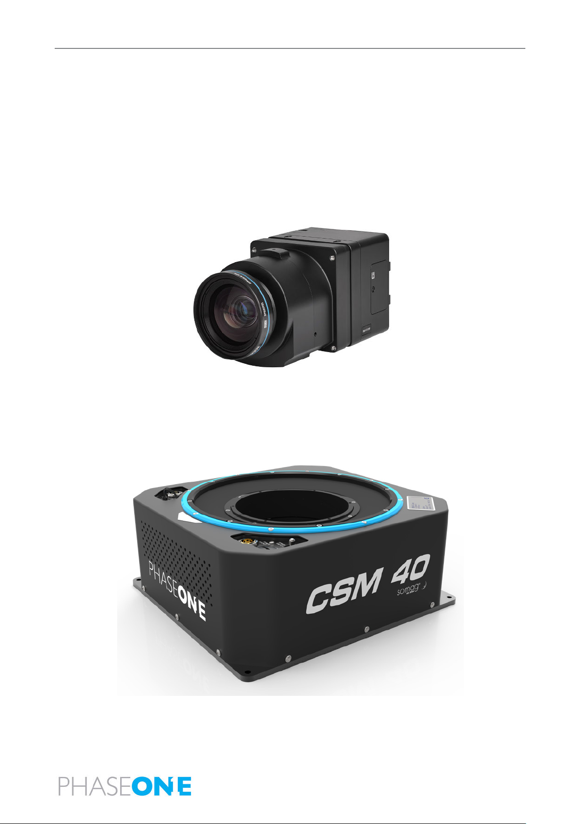
2.1.2 iXM-RS 150F Camera Head and Lenses...........................................................................................................7
2.1.3 SOMAG CSM 40 Mount............................................................................................................................................7
2.1.4 Single-Band System Frame....................................................................................................................................8
2.1.5 Applanix GNSS/IMU ...................................................................................................................................................8
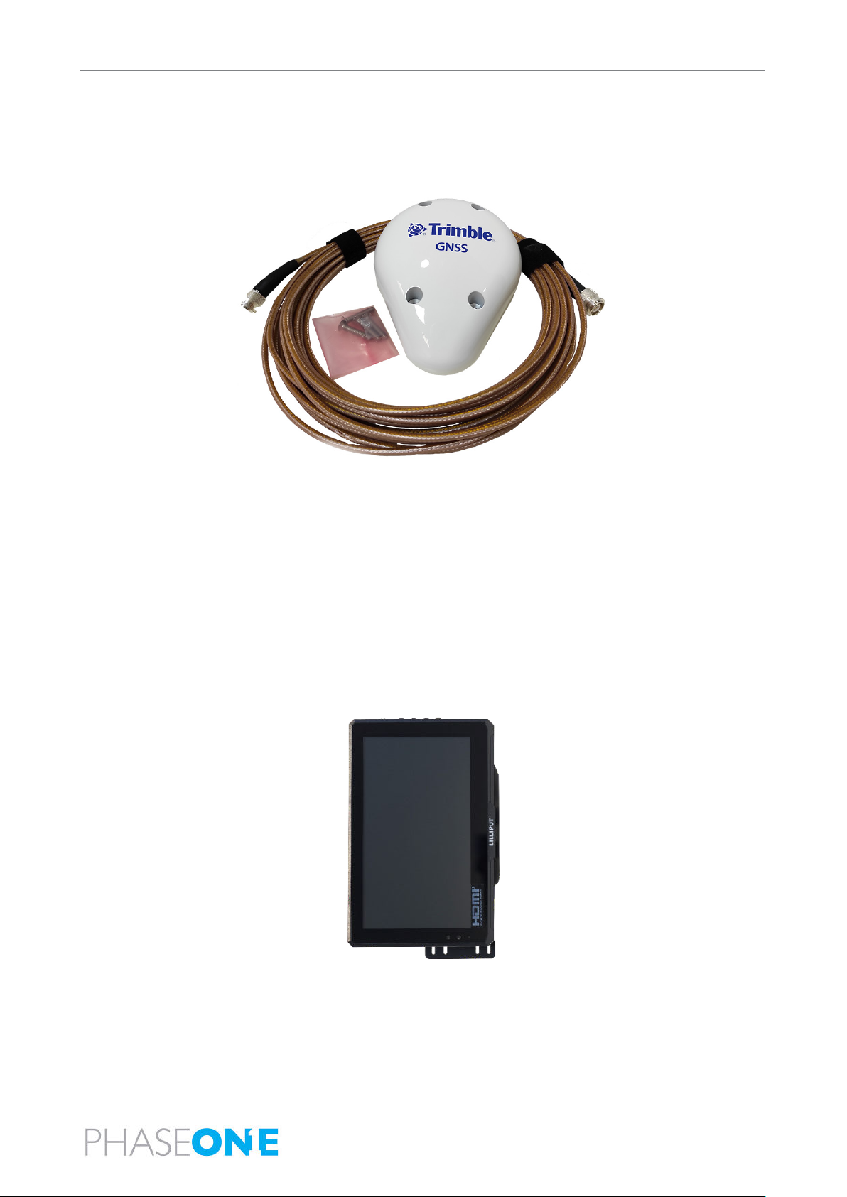
2.1.6 Trimble AV39 Antenna .............................................................................................................................................9
2.1.7 Monitor Kit.......................................................................................................................................................................9
2.2 Hardware for 4-Band System...............................................................................................................................................10
2.2.1 iXM-RS150F Achromatic 50mm RS ...................................................................................................................11
2.2.2 SOMAG DSM 400 Mount.........................................................................................................................................11
2.3 Software........................................................................................................................................................................................... 12
2.3.1 iX Flight Pro .................................................................................................................................................................. 12
2.3.2 Licensing......................................................................................................................................................................... 12
3Unboxing the System.............................................................................................................................................................................. 13
3.1 Product Identification ............................................................................................................................................................... 13
4Assembling and Testing the System in the Office ..................................................................................................................14
4.1Required Tools..............................................................................................................................................................................14
4.2 Assembling a Single-Band System ....................................................................................................................................14
4.2.1 Securing the iXM-RS 150F Camera to the Frame .....................................................................................14
4.2.2 Securing the Frame/Camera Assembly to the CSM 40 Mount (Optional)................................. 15
4.2.3 Connecting Cables to the Camera.................................................................................................................... 16
4.2.4 Securing the Lid on the Frame........................................................................................................................... 17
4.2.5 Securing the IMU to the Lid.................................................................................................................................. 17
4.2.6 Connecting a Single-Band System................................................................................................................... 18
4.3 Assembling a 4-Band System .............................................................................................................................................. 21
4.3.1 Connecting the 4-Band System......................................................................................................................... 21
4.4 System Dataflow ........................................................................................................................................................................25
4.5 Powering the System ...............................................................................................................................................................25
4.6 Configuring the System..........................................................................................................................................................26
4.6.1 Changing Pilot Monitor Orientation................................................................................................................26
4.6.2 Changing the Mouse Pointer Color .................................................................................................................28
4.6.3 Configuring Touch Monitors ...............................................................................................................................30

PAS 150/iX Controller MK5 Operation Guide
Table of Contents
Page 4 of
42
4.6.4 Check Camera Firmware for Updates ...........................................................................................................32
4.6.5 Configuring GNSS/IMU Parameters................................................................................................................ 32
4.6.6 Configuring Screen Recorder Pro....................................................................................................................32
4.6.7 Configuring iX Flight Pro ......................................................................................................................................34
4.6.8 Checking the System..............................................................................................................................................34
5Installing the System in the Aircraft...............................................................................................................................................35
5.1.1 Installing the Trimble AV39 Antenna .............................................................................................................35
5.1.2 Securing the Interface Plate to the Aircraft................................................................................................ 35
5.1.3 Securing the Mount to the Interface Plate ..................................................................................................35
5.1.4Installing the Pilot Monitor ...................................................................................................................................36
5.1.5 Installing the Operator Monitor.........................................................................................................................36
5.1.6 Connecting the System to the Aircraft Power Source ......................................................................... 37
6Recommended Flight Operation Procedure .............................................................................................................................38
7Post Flight Operations ..........................................................................................................................................................................39
8Disassembling the System ................................................................................................................................................................. 40
9Troubleshooting.........................................................................................................................................................................................41
10 Technical Data ...........................................................................................................................................................................................42
10.1 System Weight............................................................................................................................................................................42
10.1.1 Single-Band System ................................................................................................................................................42
10.1.2 4-Band System...........................................................................................................................................................42
10.2 Power Consumption.................................................................................................................................................................42

PAS 150/iX Controller MK5 Operation Guide
1. Introduction
Page 5 of
42
1Introduction
1.1 Scope
This manual describes how to install and use the PAS 150/iX Controller MK5 with iX Controller MK5 aerial
system as follows:
•Section 2 - System Overview
•Section 3- Unboxing the System
•Section 4 – Assembling and Testing the System in the Office
•Section 5 - Installing the System in the Aircraft
•Section 6 – Recommended Flight Operation Procedure
•Section 7 – Post Flight Operations
•Section 8 – Disassembling the System
•Section 9 – Troubleshooting
•Section 10 - Technical Data
1.2 Applicable Documents
Item
Manual
Applanix GNSS/IMU
GNSS/IMU Configuration Guide for PAS (release pending)
Phase One iX Flight Pro
iX Flight Pro Operation Guide
Somag CSM 40 Mount
SOMAG CSM 40 Manual
Somag DSM 400 Mount
SOMAG DSM 400 Manual
Trimble AV39 Antenna
Trimble AV39 Antenna Datasheet

PAS 150/iX Controller MK5 Operation Guide
2. System Overview
Page 6 of
42
2System Overview
The PAS 150/iX Controller MK5 is a fully integrated solution based on iXM-RS150F cameras. The aerial
system comprises the camera(s), Phase One iX Controller MK5, Applanix GNSS/IMU, SOMAG mount, and
the Phase One iX Suite (software).
Two configurations are available:
•Single-Band System
•4-Band system
2.1 Hardware for Single Band System
The following figure shows the main components of the single-band system.
2.1.1 iX Controller MK5
The iX Controller is the communication center, and 1 TB data storage for the PAS. The Microsoft
Windows 10-based system is responsible for controlling power and communication for all ancillary systems.
The storage solution consists of 2 x 500 GB SATA SSDs.

PAS 150/iX Controller MK5 Operation Guide
2. System Overview
Page 7 of
42
2.1.2 iXM-RS 150F Camera Head and Lenses
The iXM-RS 150F camera is equipped with a full-frame sensor (14,204 x 10,652 pixels), and a 3.76
micrometer pixel that enables higher ground resolution from higher flight altitudes. It provides large aerial
coverage resulting in higher aerial survey productivity.
The camera comes with one of eight RS lenses ranging from 32mm to 180mm focal length, and the 300mm
RSM lens, all equipped with a central leaf shutter to ensure geometrically correct aerial images.
Designed and built for aerial photography by Rodenstock and Schneider Kreuznach, the lenses are factory
calibrated for infinity focus and equipped with a central leaf shutter with a speed to up to 1/2500 sec. The
150MP camera offers high capture speed of 2fps for an array of flight conditions. The RS lenses opening
angle is specially fitted for oblique and lidar systems.
2.1.3 SOMAG CSM 40 Mount
The SOMAG CSM 40 is a compact modular mount specifically designed for our Phase One Aerial Systems.
With a low weight of 5.2kg and a high payload of 15kg, the special mount system is particularly suitable for
use on light aircraft.

PAS 150/iX Controller MK5 Operation Guide
2. System Overview
Page 8 of
42
2.1.4 Single-Band System Frame
The single-band system frame enables mounting the camera and the IMU.
2.1.5 Applanix GNSS/IMU
The Applanix GNSS/IMU contains a precision GNSS receiver and inertial sensor components, logging
capability, and interfaces for mapping sensors and flight management systems.
Data such as geographic position (latitude, longitude and attitude), velocity, acceleration, angular rate,
orientation (roll and pitch), ground track and performance metrics are available in real-time and through
post-processing.
The Applanix GNSS/IMU is comprised of:
•Applanix AP+ card integrated in the iX Controller MK5. The following models can be used:
AP+ 180
AP+ 310
AP+ 510
AP+ 610
•Inertial Measurement Unit (IMU). The following models can be used:
IMU-57
IMU-69
IMU-82
IMU-91
Note
For detailed information on the differences between the above Applanix GNSS/IMUs, refer to
www.applanix.com
The Applanix GNSS is configured and managed through a browser-based application supported by the
Applanix AP+ card. You can access the application through the shortcut on the iX Controller MK5 taskbar.

PAS 150/iX Controller MK5 Operation Guide
2. System Overview
Page 9 of
42
2.1.6 Trimble AV39 Antenna
The Trimble AV39 antenna is a lightweight, TSO certified antenna that provides centimeter precision with
superior phase center repeatability. The antenna is powered by the Applanix AP+ card in the iX Controller
via a coaxial cable supplied with the antenna.
2.1.7 Monitor Kit
The monitor kit allows full control and flight feedback of the entire system. The monitor kit consists of the
following monitors:
•pilot monitor
•operator monitor
2.1.7.1 Pilot Monitor
The 7” pilot monitor provides all flight information from iX Flight Pro, ensuring that the pilot has all required
information to conduct a successful survey mission. The touch screen allows the pilot to perform several
quick-access operations in iX Flight Pro (map display, zoom, line selection).

PAS 150/iX Controller MK5 Operation Guide
2. System Overview
Page 10 of
42
2.1.7.2 Operator Monitor
The 15.6” operator monitor provides all required information from iX Flight Pro, ensuring the operator can
control all aspects of the flight, including, run selection, camera control, and data management using the
touch screen.
2.2 Hardware for 4-Band System
The following figure shows the main components of the 4-band system.
The following 4-Band system components are preassembled into the 4-band frame:
•2 cameras (RGB and achromatic)
•iX Controller
•IMU
This section describes the components that are unique to the 4-band system.

PAS 150/iX Controller MK5 Operation Guide
2. System Overview
Page 11 of
42
2.2.1 iXM-RS150F Achromatic 50mm RS
In addition to the iXM-RS 150F camera, the 4-band system contains the iXM-RS 150F achromatic camera
(P/N 72199000) to provide NIR data in the spectral range of 720nm-1000nm (4-Band System).
Post processing this data in combination with the iXM-RS 150F RGB data allows output imagery in IRG, RGBi
or NDVI CIR format.
2.2.2 SOMAG DSM 400 Mount
If you are using the 4-Band system, you must install the 4-Band System Frame into a DSM 400 mount
(76013500).
The SOMAG DSM 400 is a high-performance gyro-stabilized platform that compensates for roll, pitch and
drift movements in real-time. The dynamic reaction times and the compensation ability of this platform
ensures your imagery remains fully vertical even in challenging conditions, while maintaining the high levels
of accuracy and efficiency.
SOMAG DSM 400 Mount is an electromechanical gimbal system.

PAS 150/iX Controller MK5 Operation Guide
2. System Overview
Page 12 of
42
2.3 Software
2.3.1 iX Flight Pro
iX Flight Pro uses iX Plan data to manage and guide the precise execution of aero-photography flight. Using
the pilot and operator monitors, the pilot can easily maintain precise trajectory by following altitude and
localizer instructions, while the operator manages the flight, controls the order of passes, tags images and
start/stops image collection. In the PAS 150/iX Controller MK5 system, iX Flight Pro is pre-installed on iX
Controller MK5.
For detailed information on using iX Flight Pro, see the iX Flight Pro Operation Guide provided with your
PAS 150/iX Controller MK5 aerial system.
2.3.2 Licensing
Software licensing is enabled as follows:
•iX Flight Pro - software license is preinstalled on the controller.

PAS 150/iX Controller MK5 Operation Guide
3. Unboxing the System
Page 13 of
42
3Unboxing the System
Verify that all parts were supplied according to the specific packing list for your system.
3.1 Product Identification
To enable support for your system, you must identify and record the model and serial numbers for each of
the following components:
•Cameras: the model number and serial number is located on two labels in the middle section joining both
cameras.
•Mount: model number and serial number is located on a label on the mount.
•IMU: model number and serial number is located on a label on the unit.

PAS 150/iX Controller MK5 Operation Guide
4. Assembling and Testing the System in the Office
Page 14 of
42
4Assembling and Testing the System in the Office
This section describes how to assemble the system for testing in the office.
Phase One recommends assembling and testing the entire system in the office prior to transporting it and
installing it in the aircraft. This allows for quick installation in the aircraft with little risk of missing cables or
incorrect configuration.
Note
•When placing the system down on a work bench, make sure that the area is clear of
debris to avoid damaging the lens. In the case of a 4-band system the frame legs provide
ample clearance between the lenses and the surface, but any objects underneath the
system, including loose cables, could impact the lenses.
•Make sure you place the system on a work bench capable of withstanding the system
weight.
4.1 Required Tools
The following tools are required to assemble the system in the office:
•Allen keys set.
•Torx keys set.
•Standard tools.
•Lens Cleaning Kit.
•Microfiber Cloth, Grey.
4.2 Assembling a Single-Band System
4.2.1 Securing the iXM-RS 150F Camera to the Frame
1. Insert the camera into the frame (image at right
shows top view).

PAS 150/iX Controller MK5 Operation Guide
4. Assembling and Testing the System in the Office
Page 15 of
42
2. Secure the camera to the frame using four M4x16
screws (image at right shows bottom). Tighten the
screws to torque 2Nm.
4.2.2 Securing the Frame/Camera Assembly to the CSM 40 Mount (Optional)
Note
The frame with the camera and IMU does not have to be assembled in the mount for testing. You can
place the mount next to the frame.
1. Insert the frame/camera assembly into the mount.
The direction of the logo on the camera
should be aligned with the white arrow on the
mount.
2. If necessary, adjust the height of the frame/camera
assembly within the mount using the 6 screws on
the frame. The height should be such that camera
will not protrude beyond the aircraft skin.
3. Secure the frame to the mount using 6 M4x16
screws, spring washers and washers. Tighten the
screws to torque 2Nm.

PAS 150/iX Controller MK5 Operation Guide
4. Assembling and Testing the System in the Office
Page 16 of
42
4.2.3 Connecting Cables to the Camera
1. Connect the iX Controller MK5 / Camera USB Cable
(73234000) angled USB connector to the camera
USB port. Tighten the screws to torque 0.25Nm.
2. Connect the Camera Control Cable (70378000) to
the left LEMO port.
3. Connect the Camera Power Cable (70364000) to
the right LEMO port.

PAS 150/iX Controller MK5 Operation Guide
4. Assembling and Testing the System in the Office
Page 17 of
42
4.2.4 Securing the Lid on the Frame
1. Secure the lid to the top of the frame using 9 M4x10
screws. Tighten the screws to torque 2Nm.
4.2.5 Securing the IMU to the Lid
1. Secure the IMU to the lid using 4 M6x16 screws,
spring washers and washers. Tighten the screws to
torque 3Nm.
2. Note the direction of the IMU X axis. If it is not the
same as the flight direction, configure it in the AP+ application on the External IMU tab.

PAS 150/iX Controller MK5 Operation Guide
4. Assembling and Testing the System in the Office
Page 18 of
42
4.2.6 Connecting a Single-Band System
Note
•Do not excessively bend cables. Allow a bending radius of at least 40mm for all cables.
•Insert connectors into ports with care to prevent damage to pins.
•Make sure that the monitor port connector is properly secured.
•Use cable ties to secure the cables to the appropriate points on the monitor to ensure
that the connectors are secured.
To connect the system:
1. Connect all system components as described in the following table and figures (power and
communication connections for main system components and keyboard and pilot and operator monitor
connections).
2. Place the antenna outside an open window in full view of the sky.
PAS 150/iX Controller MK5 Single-Band System Connection Details
Order
P/N
Description
Connects to
1
75028000
PAS Power cable
•Aircraft Power Source (add suitable
connector - see 5.1.6 - Connecting the
System to the Aircraft Power Source for
pinout)
•CSM 40 Mount, POWER SOCKET port
•iX Controller, 28 VDC port
2
70364000
Power cable, iX Controller/Camera
•iX Controller, AUX2 ports
•iXM-150, right-LEMO port*
3
73234000
USB cable
•iX Controller, USB port
•iXM-150, USB port*
4
70378000
Camera trigger & MEP
•iX Controller, I/O port
•iXM-RS 150 left LEMO port*
5
73260000
Mount control
•iX Controller, COM port
•CSM 40 Mount, INTERFACE port
6
73278000
IMU data
•iX Controller, IMU port
•IMU
7
75022000
Power, Video DP, USB harness
•Operator monitor (power, video, USB
ports)
•iX Controller AUX1 ports (power); HDMI
(video); USB ports (USB)
*Camera-side connections were already connected as described in Section 4.2.3 - Connecting
Cables to the Camera.

PAS 150/iX Controller MK5 Operation Guide
4. Assembling and Testing the System in the Office
Page 19 of
42
Order
P/N
Description
Connects to
8
75021000
Power, Video HDMI, USB harness
•Pilot monitor (power, video - includes USB
signal)
•iX Controller AUX1 ports (power); DP
(video); USB ports (USB)
9
76000600
Keyboard dongle (supplied with
keyboard) •iX Controller, USB port
10
-
Antenna cable (supplied with
antenna) •Aircraft Antenna Connector
•iX Controller (rear panel)

PAS 150/iX Controller MK5 Operation Guide
4. Assembling and Testing the System in the Office
Page 20 of
42
Single-Band System and Power Connections
This manual suits for next models
2
Table of contents
Other PhaseOne Camera Accessories manuals

PhaseOne
PhaseOne PAS Pana User manual

PhaseOne
PhaseOne PhotoPhase User manual

PhaseOne
PhaseOne H 25 User manual

PhaseOne
PhaseOne H 101 User manual

PhaseOne
PhaseOne P+ Series User manual

PhaseOne
PhaseOne PAS 150MP MK2 User manual

PhaseOne
PhaseOne FlexAdaptor User manual

PhaseOne
PhaseOne P+ Series User manual

PhaseOne
PhaseOne PhotoPhase 85280002 User manual

PhaseOne
PhaseOne iX User manual