Phcbi MCO-5M Series User manual

MCO-5MSeries
Please read the operating instructions carefully before using this product, and keep the operating
instructions for future use.
See page 52 for model number.
Operating Instructions
O2/CO2Incubator


1
CONTENTS
INTRODUCTION ................................................................................................. 2
PRECAUTIONS FOR SAFE OPERATION.......................................................... 3
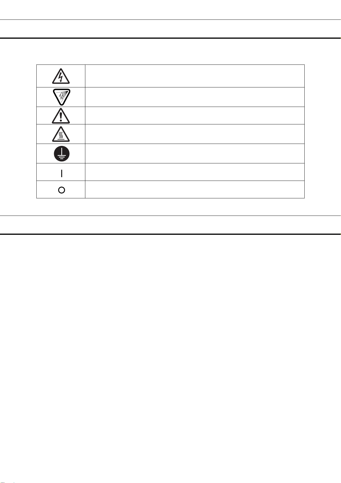
LABELS ON THE INCUBATOR .......................................................................... 8
ENVIRONMENTAL CONDITIONS ...................................................................... 8
INCUBATOR COMPONENTS ............................................................................ 9
Control panel and keypad .............................................................................. 11
Remote alarm terminals ................................................................................ 13
INSTALLATION SITE ........................................................................................ 14
INSTALLATION ................................................................................................. 15
Connecting a CO2gas cylinder ...................................................................... 16
Connecting a N2(or O2) gas cylinder ............................................................. 17
Connecting a gas injection nozzle.................................................................. 18
PREVENTING CONTAMINATION .................................................................... 19
PRECAUTIONS FOR CULTURES.................................................................... 20
INITIAL CLEANING METHOD ......................................................................... 21
REMOVING INNER ATTACHMENTS ............................................................... 22
INSTALLING INNER ATTACHMENTS.............................................................. 24
FILLING THE HUMIDIFYING PAN.................................................................... 25
WATER LEVEL SENSOR.................................................................................. 26
ROUTINE MAINTENANCE................................................................................ 27
CORRECT OPERATION................................................................................... 27
OPERATION OF KEYS ON THE CONTROL PANEL....................................... 28
SETTING OF ALARM RESUME TIME.............................................................. 29
Operation after power failure.......................................................................... 29
KEY LOCK FUNCTION ..................................................................................... 30
AUTOMATIC GAS CYLINDER CHANGEOVER ............................................... 31
UV LAMP ........................................................................................................... 33
Change of setting for UV lamp ON period...................................................... 34
Precautions when using the UV lamp ............................................................ 35
Lighting the UV lamp for 24 hours.................................................................. 36
ALARMS, SAFETY, AND SELF-DIAGNOSIS ................................................... 37
CALIBRATION
Temperature calibration ................................................................................. 39
O
2calibration.................................................................................................. 40
CO
2calibration ............................................................................................... 41
TROUBLESHOOTING....................................................................................... 42
DISPOSING OF THE O2/CO2INCUBATOR...................................................... 44
STACKING INCUBATORS................................................................................ 49
SPECIFICATIONS............................................................................................. 51
PERFORMANCE............................................................................................... 52
SAFETY CHECK SHEET .................................................................................. 53

2
INTRODUCTION
■Read the operating instructions carefully before using the Product and follow the instructions for safety
operation.
■PHC Corporation disavows any responsibility for safety if the Product is used for other than the
intended use or used with any procedures other than those given in the operating instructions.
■Keep the operating instructions in a suitable place so that it can be referred to as necessary.
■The contents of the operating instructions are subject to change without notice for improvement of
performance or functions.
■Contact our sales representative or agent if any page of the operating instructions is lost or the page
order is incorrect.
■Contact our sales representative or agent if any point in the operating instructions is unclear or if there
are any inaccuracies.
■No part of the operating instructions may be reproduced in any form without the expressed written
permission of PHC Corporation.
IMPORTANT NOTICE
PHC Corporation guarantees this product under certain warranty conditions. However, please note that
PHC Corporation shall not be responsible for any loss or damage to the contents of the product.

3
PRECAUTIONS FOR SAFE OPERATION
It is imperative that the user complies with the operating instructions
as it contains important safety advice.
Items and procedures are described so that you can use this unit correctly and safely.
If the precautions advised are followed, this will prevent possible injury to the user and
any other person.
Precautions are illustrated in the following way:
WARNING
Failure to observe WARNING signs could result in a hazard to personnel
possibly resulting in serious injury or death.
CAUTION
Failure to observe CAUTION signs could result in injury to personnel and
damage to the unit and associated property.
Symbol shows;
This symbol means caution.
This symbol means an action is prohibited.
This symbol means an instruction must be followed.
Be sure to keep the operating instructions in a place accessible to users of this unit.
WARNING
As with any equipment that uses CO2gas, there is a likelihood of oxygen depletion in the vicinity
of the equipment. It is important that you assess the work site to ensure there is suitable and
sufficient ventilation. If restricted ventilation is suspected, then other methods of ensuring a
safe environment must be considered. These may include atmosphere monitoring and
warning devices.

4
PRECAUTIONS FOR SAFE OPERATION
USA Only (Model with a lamp): This product has a lamp that contains mercury. Disposal may be
regulated in your community due to environmental considerations. For disposal or information, please
visit PHC website: https://www.phchd.com.
Contains mercury / Contenu avec mercure
For more information on safe handling
procedures, the measures to be taken in
case of accidental breakage and safe
disposal options visit:
ec.gc.ca/mercure-mercury/.
Dispose of or recycle in accordance with
applicable laws.
Pour plus de renseignements sur les
procédures de manutention sécuritaire, les
mesures à prendre en cas de bris accidentel et
les options d’élimination sécuritaire visitez:
ec.gc.ca/mercure-mercury/.
Mettez au rebut ou recyclez conformément
aux lois applicables.

5
Do not use the unit outdoors. Current leakage or electric shock may result if the unit is exposed to
rain water.
Only qualified engineers or service personnel should install the unit. The installation by
unqualified personnel may cause electric shock or fire.
Install the unit on a sturdy floor and take an adequate precaution to prevent the unit from
turning over. If the floor is not strong enough or the installation site is not adequate, this may result
in injury from the unit falling or tipping over.
Never install the unit in a humid place or a place where it is likely to be splashed by water.
Deterioration of the insulation may result which could cause current leakage or electric shock.
Never install the unit in a flammable or volatile location. This may cause explosion or fire.
Never install the unit where acid or corrosive gases are present as current leakage or electric
shock may result due to corrosion.
Always ground (earth) the unit to prevent electric shock. If the power supply outlet is not
grounded, it will be necessary to install a ground by qualified engineers.
Never ground the unit through a gas pipe, water main, telephone line or lightning rod. Such
grounding may cause electric shock in the case of an incomplete circuit.
Connect the unit to a power source as indicated on the rating label attached to the unit. Use
of any other voltage or frequency other than that on the rating label may cause fire or electric shock.
Never store volatile or flammable substances in this unit if the container cannot be sealed. These
may cause explosion or fire.
Do not insert metal objects such as a pin or a wire into any vent, gap or any outlet on the unit.
This may cause electric shock or injury by accidental contact with moving parts.
Use this unit in safe area when treating the poison, harmful or radiate articles. Improper use
may cause bad effect on your health or environment.
Turn off the power switch (if provided) and disconnect the power supply to the unit prior to any
repair or maintenance of the unit in order to prevent electric shock or injury.
Do not touch any electrical parts (such as power supply plug) or operate switches with a wet
hand. This may cause electric shock.
WARNING

6
PRECAUTIONS FOR SAFE OPERATION
Ensure you do not inhale or consume medication or aerosols from around the unit at the time of
maintenance. These may be harmful to your health.
Never splash water directly onto the unit as this may cause electric shock or short circuit.
Never put containers with liquid on the unit as this may cause electric shock or short circuit when
the liquid is spilled.
Never bind, process, or step on the power supply cord, or never damage or break the power
supply plug. A broken power supply cord or plug may cause fire or electric shock.
Do not use the power supply cord if its power supply plug is loose. Such power supply cord
may cause fire or electric shock.
Never disassemble, repair, or modify the unit yourself. Any such work carried out by an
unauthorized person may result in fire, or electric shock or injury due to a malfunction.
Disconnect the power supply plug if there is something wrong with the unit. Continued
abnormal operation may cause electric shock or fire.
When removing the power supply plug from the power supply outlet, grip the power supply
plug, not the cord. Pulling the power supply cord may result in electric shock or fire by short circuit.
Disconnect the power supply plug before moving the unit. Take care not to damage the power
supply cord. A damaged power supply cord may cause electric shock or fire.
Disconnect the power supply plug when the unit is not used for long periods. Keeping the
connection may cause electric shock, current leakage, or fire due to the deterioration of insulation.
If the unit is to be stored unused in an unsupervised area for an extended period, ensure that
children do not have access and that doors cannot be closed completely.
The disposal of the unit should be accomplished by appropriate personnel. Remove doors to
prevent accidents such as suffocation.
Do not put the packing plastic bag within reach of children as suffocation may result.
Do not position this unit and the other unit so that it is difficult to operate the disconnection of
the power supply plug. Failure to disconnect the power supply plug may cause fire if there is
something wrong with the unit.
WARNING

7
This unit must be plugged into a dedicated circuit protected by branch circuit breaker.
Use a dedicated power source as indicated on the rating label attached to the unit. A multiple-tap
may cause fire resulting from abnormal heating.
Never store corrosive substances such as acid or alkali in this unit if the container cannot be
sealed. These may cause corrosion of inner components or electric parts.
Check the setting when starting up of operation after power failure or turning off of power
switch. The stored items may be damaged due to the change of setting.
Be careful not to tip over the unit during movement to prevent damage or injury.
Prepare a safety check sheet (copy the last page) when you request any repair or maintenance for
the safety of service personnel.
CAUTION

8
LABELS ON THE INCUBATOR
Warning and caution labels are attached to the incubator. The following table describes the labels.
This label is attached to covers that access high-voltage electrical components to
prevent electric shock. Only a qualified engineer or service personnel should be
allowed to open these covers.
This symbol indicates an ultraviolet light (UV) caution.
This symbol indicates that caution is required. Refer to product documentation for
details.
This symbol indicates a hot surface.
This symbol indicates an earth.
This symbol means “ON” for a power switch.
This symbol means “OFF” for a power switch.
ENVIRONMENTAL CONDITIONS
This equipment is designed to be safe at least under the following conditions (based on the IEC 61010-1):
■Indoor use;
■Altitude up to 2000 m;
■Temperature 5 oC to 40 oC
■Maximum relative humidity 80 % for temperature up to 31 oC decreasing linearly to 50 % relative
humidity at 40 oC;
■Mains supply voltage fluctuations up to ±10 % of the nominal voltage;
■Transient overvoltages up to the levels of OVERVOLTAGE CATEGORY II;
■Temporary OVERVOLTAGES occurring on the mains supply;
■Applicable pollution degree of the intended environment (POLLUTION DEGREE 2 in most cases);

9
INCUBATOR COMPONENTS
Rear left side
Rear right side
10
20
1 2
3
4
5 12 6 7 (inside)
8
13 ,15 ,16(inside)
19
14
When MCO-19UVS is
installed
When MCO-19UVS is
installed
18
Switch cover
19
8
9
17
22
21
Changeable
Connecting port for N2/O2gas
Connectin
g
p
ort for CO2
g
as
11
23

10
INCUBATOR COMPONENTS
1. Outer door: Sticks to frame with magnetic seal. Door heater is installed in the door panel. The
door opening is reversible. Contact our sales representative or agent to change the door hinge from left
to right or vice versa.
2. Inner door: Made of tempered glass, however avoid excessive impact on the glass.
3. Leveling feet: Screw type for adjusting the height. Adjust the feet so that the unit can be level.
4. Tray: Can be pulled toward you.
5. Side support: Right and left side supports can be removed for disinfection. See page 22 and 23.
6. Rear duct: Flow path for circulating air. Removable.
7. Fan (inside the rear duct): Made from polypropylene resin. Can be sterilized by an autoclave.
8. Sample air outlet: This also functions as an internal gas outlet. Use only a supplied cap(9).
9. Sample air outlet cap: Always attach this cap except at the time of using of sample air outlet.
10. Connecting port A/B for CO2gas pipe (rear side): When an optional component MCO-5GC (gas
auto changer) is installed, both A and B are available. If MCO-5GC is not installed, only A is available.
Refer to page 16 for gas cylinder connection. Ensure that the gas pressure is set at 0.03 MPa(G) (0.3
kgf/cm2(G), 4.4 psi(G)). Refer to page 31 for automatic gas cylinder changeover.
11. Connecting port A/B for N2/O2gas pipe (rear side): Refer to page 17 for gas cylinder connection.
Ensure that gas pressure is set at 0.05 MPa(G) (0.5 kgf/cm2(G), 7.3 psi(G)). Refer to page 31 for
automatic gas cylinder changeover.
12. Door switch: Detects the door opening/closing and stops the circulating fan and electromagnetic
valve for CO2and N2/O2when door is open. UV lamp is also deactivated by door opening (When an
optional UV system set MCO-19UVS is installed).
13. Humidifying pan: Use sterile distilled water to fill the humidifying pan.
14. Humidifying pan cover: Prevents UV light being exposed to the chamber. When filling the
humidifying pan, lift the front side and take out the humidifying pan. See page 25 for details.
15. UV lamp (When an optional UV system set MCO-19UVS is installed):
This UV lamp does not generate ozone. Never look at the UV light directly. For replacement, contact
our sales representative or agent.
16. Water level sensor: Detects the water level in the humidifying pan. See page 26 for details.
17. Remote alarm terminal: Refer to page 13.
18. Access port: When not in use, cap with the silicon caps on both outside and inside.
19. Power switch: Main switch of the unit (ON-“I”, OFF-“O”). Also functions as an over-current
breaker. The switch is covered by a switch cover to prevent the accidental push. To turn on or off the
switch, remove the switch cover by loosening the screw. See figure on the right.
20. Glow starter (When an optional UV system set MCO-19UVS is installed):For UV lamp (model;
FG-7P)
21. Power supply removable cord
22. Handle: Outer door handle. When moving the handle from upper to a lower position remove it from
original position first, then remove two cups and screws at the lower position and attach the handle there.
23. Gas injection nozzle: Refer to page 18.

11
Control panel and keypad
1. Digital temperature indicator (TEMPERATURE oC): Normally, this indicator shows the chamber
temperature. In the setting mode, it shows the set value of the chamber temperature. If the self
diagnostic function detects any abnormality, an error code will be displayed.
2. Heater lamp (HEAT): This lamp lights when the heater is energized.
3. UV indicator (UV): This lamp lights when the UV lamp is ON. The blink of this indicator
recommends the replacement of UV lamp. See page 33 for the details.
4. Door lamp (DOOR): This lamp lights when the outer door is open.
5. Water level alarm lamp (RH PAN): This lamp blinks when the water in the humidifying pan is less
than approximately 0.8 liter.
6. High limit regulator: This regulator is used to set the high limit temperature.
7. Over heat lamp (OVER HEAT): This lamp lights when the chamber temperature reaches the high
limit set value.
8. CO2inject lamp (INJECT): This lamp lights when CO2gas is being injected.
9. Digital CO2density indicator (CO2%): Normally, this indicator shows the CO2density in the
chamber. In the setting mode, it indicates the set value of the CO2density. The empty gas supply line
is displayed when CO2gas cylinder becomes empty (only when MCO-5GC is installed). See page 31 for
details.
10. O2inject lamp (INJECT): This lamp lights when N2 or O2gas is being injected.
11. Digital O2density indicator (O2%): Normally, this indicator shows the O2density in the chamber.
In the setting mode, it indicates the set value of the O2density. The empty gas supply line is displayed
when N2or O2gas cylinder becomes empty (only when MCO-5GC is installed). See page 31 for details.
1
4
5
7
23
6
8 9 10 11

12
INCUBATOR COMPONENTS
12. Set key (SET): Pressing this key to enter the setting mode, and the digits to be set will blink.
13. Calibration key (CAL): By pressing this key for approximately 5 seconds, the unit enters calibration
function mode. See page 39 for the details. Also, used to change the UV lamp ON period. See page
34 for the details.
14. Alarm buzzer stop key (BUZZER): Press this key to silence the buzzer when the alarm operates
and the buzzer sounds.
15. N2/O2gas supply line indicator (A/B): The lamp for the N2/O2gas supply line currently in use lights
up. (Lamp ON; cylinder A, Lamp blinks; cylinder B)
16. CO2gas supply line indicator (A/B): The lamp for the CO2gas supply line currently in use lights up
provided that gas auto changer MCO-5GC is installed. (Lamp ON; cylinder A, Lamp blinks; cylinder B)
17. Gas supply line switching key (GAS SUPPLY): This is a key to select N2or O2gas supply. By
pressing this key, the N2or O2gas supply line (A/B) is changed in O2 density set mode. The supply line
is changed automatically when N2or O2gas cylinder is empty. Similarly, by pressing this key in CO2
density set mode, CO2gas supply line is changed automatically when a gas auto changer MCO-5GC
(option) is installed. The supply line is changed automatically when CO2gas cylinder is empty.
18. Enter key (ENT): Pressing this key memorizes the set value in the controller.
19. Numerical value shift key ( ): Pressing this key in the setting mode causes the numerical value
to shift. In key lock mode, pressing this key makes key lock ON or OFF.
20. Digit shift key ( ): Pressing this key in the setting mode causes the changeable digit to shift.
Pressing this key more than 5 seconds enters key lock mode. See page 30 for the key lock.
12 13 14
15
181920
1716

13
Remote alarm terminals
The remote alarm terminal is located at the rear right side.
The remote alarm terminal is a contact output.
Normal : OPEN
Abnormal , blackout : CLOSE
Contact capacity : DC 30 V, 2 A
Note:
• When the power switch is OFF or the power failure condition, the contact output is CLOSE.
• The remote alarm cannot be silenced by pressing the alarm buzzer stop key (BUZZER) since the
remote alarm is not conjunct with the alarm buzzer stop key (BUZZER) key.
Remote alarm terminal
REMOTE ALARM
MAX DC30V 2A
N. O.

14
INSTALLATION SITE
For correct operation of the incubator, install it in a location with the following conditions.
WARNING
When using CO2/N2gas for control, make sure that there is adequate ventilation. Using CO2/N2gas in
a small room without adequate ventilation may cause gas poisoning or oxygen deprivation. In addition,
when opening the incubator doors, do not directly inhale the air in the chamber.
Si l’appareil est utilisé dans un evdroit restreint, le niveau de la densite CO2/N2de l’air peut s’élever et
peut être nocif aux humains. Evitez d’aspirer l’air provenant de l’inérieur de l’appareil quand vous ouverz
la porte.
Normal air environment
Install the incubator in an environment with normal air.
Do not expose to direct sunlight
Do not install the incubator in a location where it will be exposed to direct sunlight. If the incubator is
operated in direct sunlight, performance will be adversely affected.
Separate from heat sources
Do not install the incubator near significant heat sources, such as heaters, boilers, ovens, or autoclaves.
Heat will adversely affect the performance of the incubator.
Ambient temperature at least 5 C lower than set temperature
The control temperature of the incubator is at least 5 C higher than the ambient temperature. For
example, if the chamber is controlled at 37 C, the ambient temperature must normally be no more than
32 C. Do not allow the ambient temperature to become too high.
Strong and level floor
Select a site with a strong and level floor. If the floor is uneven or the installation is not level, the incubator
will be unstable and this may cause accident or injury. To avoid vibration and noise, always make sure
that the installation is stable. An unstable surface may result in vibration or noise.
WARNING
Install the incubator at a location that can support the weight. If the floor is not strong enough or if the
installation is insufficient, the incubator may fall over and cause injury.
Always make sure that the floor is strong, even, and level, and that the incubator will not tip over.
An insufficient installation may result in injury due to water leakage or the incubator falling over.
Low humidity
Select a site with a relative humidity of 80 %R.H. or lower. Using the incubator in high humidity may result
in current leakage or electric shock.
WARNING
Do not use the incubator outdoors. If the incubator is exposed to rain water, it may result in current
leakage or electric shock.
Never install the Incubator in a moist location, such as near a sink or water line, or where it is
likely to be exposed to water. In addition, do not install it near water or steam pipes. Moisture can
cause the insulation to deteriorate, which may result in current leakage or electric shock.
No inflammable or corrosive gas
Never install the incubator in a location where it will be exposed to inflammable or corrosive gas. Doing so
may result in explosion or fire. In addition, insulation may deteriorate due to corrosion of protective casing,
resulting in current leakage or electric shock.
No falling objects
Do not install the incubator in a location where there is the possibility of objects falling from above. Doing
so may result in damage or accident.

15
INSTALLATION
1. Remove the packing tape and clean up.
Remove all the tape that is securing the doors and inner attachments. Open the doors for ventilation. If
the outer panels are dirty, dampen a cloth with a diluted neutral detergent and wipe them. (Using an
undiluted solution may damage the plastic. Follow the diluting instructions for the detergent that is used.)
Wipe off the residual detergent with a wet cloth and then wipe off any moisture.
Note:
Remove the cable tie banding the power supply removable cord. Prolonged banding may cause the
corrosion of the cord coating.
WARNING
Do not leave plastic wrapping bags within reach of children. If a bag is placed over a child’s head, it
can block the mouth and nose and cause suffocation.
2. Adjust the leveling feet.
Adjust the leveling feet by turning them counterclockwise to level
the incubator. (See the illustration on the right.)
3. Ground the incubator.
Ground the incubator during installation to prevent electric shock
in case the insulation is not sufficient. If there is no ground wire at
the location, consult with qualified service personnel.
When a ground must be installed
If a grounded 3-pole outlet is not available, then a ground must
be installed. Consult with qualified service personnel.
WARNING
To prevent electric shock, always ground the incubator. If grounding is not possible, then have a ground
installed by qualified personnel. If the incubator is not grounded, it may result in electric shock.
Never connect the ground wire to a gas pipe, water pipe, lightning rod, or telephone ground wire.
Doing so may cause electric shock.
Installing a ground fault circuit breaker
If using the incubator in a location with moisture or humidity cannot be avoided, then it is recommended
that a ground fault circuit breaker be installed in the power supply circuit (i.e., the power supply at the
incubator). Have the circuit breaker installed by qualified service personnel.
CAUTION
Do not climb on the incubator or place objects on top of it. Doing so may damage it or cause it to fall
over, resulting in injury. If it is to be stacked, refer to page 49 and stack it securely.
When the incubator is not in use
Empty the water from the humidifying pan and remove moisture from the chamber. Make sure that the
chamber is completely dry before closing the doors. Failure to do so may result in damage.
Before moving the incubator
Before moving the incubator, empty the water from the humidifying pan, disconnect the power supply plug
from the outlet, and make sure that the power supply cord will not be damaged. Failure to do so may
result in electric shock or fire.
Leveling feet

16
INSTALLATION
Connecting a CO2gas cylinder
WARNING
When connecting a gas cylinder to the incubator, confirm the gas type. Confirm that the connections
are secure and that no gas will escape. Be sure to use the specified pressure. Using an incorrect
gas or pressure may result in explosion or fire, or in gas poisoning or oxygen deprivation due to escaping
gas.
Install the incubator in a location with adequate ventilation. If adequate ventilation cannot be
provided, then install an alarm system using CO2and O2 densitometers.
1. Use a liquefied CO2gas cylinder (at least 99.5 % pure). The siphon (dip tube) type cannot be used.
2. Install a gas regulator rated at 25 MPa(G) (250 kgf/cm2(G), 3600 psi(G)) for the primary pressure, and
0.25 MPa(G) (2.5 kgf/cm2(G), 36 psi(G)) for the secondary pressure on the CO2gas cylinder.
3. Using the gas tube that is provided, connect the gas regulator to the connecting port A/B for CO2gas
pipe (located at the rear left side of the incubator).
Note:
If CO2is supplied to multiple CO2incubators from a single gas cylinder, a CO2solid will be formed in the
gas regulator. The gas regulator safety valve will operate, and there may an explosive sound.
When the MCO-5GC is not mounted
Using the gas tube that is provided, connect the gas regulator for the CO2gas cylinder to connecting port
A for CO2gas pipe on the incubator. After connecting the gas tube, check to make sure that no gas is
leaking.
When the MCO-5GC is mounted
Connect a pair of CO2gas cylinders with gas regulators independently. The gas supply line will be
switched automatically. Connect the main cylinder to connecting port A for CO2gas pipe and the reserve
cylinder to connecting port B for CO2gas pipe. After connecting the cylinders, check to make sure that no
gas is leaking.
For details on installing the optional gas auto changer (MCO-5GC), refer to the MCO-5GC installation
guide. For details on using the MCO-5GC, refer to page 31.
4. Set the CO2gas on the secondary side to 0.03 MPa(G) (0.3 kgf/cm2(G), 4.4 psi(G)) for gas injection. As
the pressure increases, the CO2gas density control range will increase. Excessive pressure may cause
gas supply lines inside the incubator to come loose, which may result in gas poisoning or oxygen
deprivation due to the escaping of gas. If gas lines come loose, the incubator must be repaired.
The gas lines connected to the incubator will degrade over time. If any deterioration or abnormalities
are found during inspection, replace the lines immediately.

17
Connecting a N2(or O2 ) gas cylinder
WARNING
Check the gas type and ensure that it is fit for the purpose. Make sure that all pipes are
connected correctly and are not liable to become disconnected. Ensure that the gas pressure is
set at the specified value. Improper connection of the gas pipe or use of incorrect gas pressure
may result in leakage of gas. Elevated level of gas can be hazardous to health and may lead to
asphyxiation and risk of death.
This incubator needs N2or O2gas depending on the setting of O2 density. The selection is as follows:
When the setting of O2 density is less than 18 %: N2 gas
When the setting of O2 density is more than 22 %: O2 gas
O2 density in the atmosphere is about 20 %. For the control of O2 density in the chamber, O2 gas is
diluted by N2 gas when the setting of O2 density is less than that of the atmosphere. On the contrary, O2
gas is added when the setting of O2 density is more than that of the atmosphere.
1. Install a gas regulator rated at 25 MPa(G) (250 kgf/cm2(G), 3600 psi(G)) on the primary side and 0.2
5MPa(G) (2.5 kgf/cm2(G), 36 psi(G)) on the secondary side on N2or O2gas cylinder.
2. Using the gas supply tube provided, connect the gas regulator to the connecting port A/B for N2 or O2
gas pipe located at the rear left side of the incubator. Connect the main cylinder to the connecting port A
for N2 or O2gas pipe and connect the sub-cylinder to the connecting port B for N2 or O2gas pipe so that
the gas supply can be switched automatically when one gas cylinder is empty. Connect the same gas
type to both connecting port A and B for N2 or O2gas pipe . Never connect N2 gas and O2 gas at the
same time to the connecting port A and B for N2 or O2gas pipe respectively.
3. Set the N2 or O2gas pressure on the secondary side to 0.05 MPa(G) (0.5 kgf/cm2(G), 7.3psi(G)) (at gas
injection). The higher gas pressure makes control range of O2density wider. In addition, excessive
pressure may cause disconnection of internal pipes inside the incubator, which will result in leakage of N2
or O2 gas into the atmosphere. Elevated level of CO2 gas or O2 gas can be hazardous to health and
may lead to asphyxiation and risk of death or fire by gas leakage. The repair of the incubator will be
necessary if the internal pipe is disconnected.
4. Check that no gas is leaking at any point where the pipe connects with the gas regulator or the
incubator.
The gas lines connected to the incubator will degrade over time. If any deterioration or abnormalities
are found during inspection, replace the lines immediately.
WARNING
O2gas increases the susceptibility of substances to burn. Take care of the handling of flame in a room
where the incubator is installed.

18
INSTALLATION
Connecting a gas injection nozzle
In the case of control of O2density in the chamber, connect the gas injection nozzle to the gas injection
port by using the gas injection nozzle tube enclosed (inner diameter; 5 mm, outer diameter; 9 mm, length;
300 mm). This helps faster recovery of humidity after opening of the inner door.
Fill the humidifying pan with sterile distilled water so that the gas injection nozzle can be under the water
level.
1. Inside of unit is arranged as shown in Fig. 1 when humidifying pan cover removed. There is a gas
injection port in the lower left-hand corner.
2. Connect gas injection nozzle to gas injection port using gas injection nozzle tube. (Fig. 2)
3. Connecting gas injection nozzle is as shown in Fig. 3.
Fig.1 Fig.2 Fig.3
Gas injection nozzle
Gas injection port Gas injection nozzle tube
This manual suits for next models
4
Table of contents
Other Phcbi Accessories manuals

Phcbi
Phcbi MCO-18ACL User manual

Phcbi
Phcbi MCO-170AICD-PE User manual

Phcbi
Phcbi MCO-170AICUVDL User manual

Phcbi
Phcbi MCO-170AIC User manual

Phcbi
Phcbi MCO-170AC User manual

Phcbi
Phcbi MCO-170AICDL User manual

Phcbi
Phcbi MCO-18AC Series User manual

Phcbi
Phcbi MCO-170ML User manual

Phcbi
Phcbi MIR-H163 Series User manual

Phcbi
Phcbi MCO-230AICUVL User manual