PhDsolutions HDBaseT MXC-4K888-HDT150-KIT User manual

HDBaseT™ 18Gb 8X8 150m Matrix Kit
0;&.+'7.,7
VER 1.0_ 07-01-2022- MXC-4K888-HDT150—KIT manual
User Manual

Thank you for purchasing this product
Surge protection device recommended
For optimum performance and safety, please read these instructions carefully before connecting,
operating or adjusting this product. Please keep this manual for future reference.
This product contains sensitive electrical components that may be damaged by
electrical spikes, power surges, electrostatic discharge (ESD), lightning strikes or
transients. The use of surge protection systems is highly recommended to protect and
extend the life of your equipment.
Safety & performance notice
The transmission distances of HDMI over UTP Cat cables are measured using TE
CONNECTIVITY 1427071-6.
EIA TIA-568-B termination (T568B) of cables is essential for optimal performance.
Do not run the HDBaseT™ / Cat5e/6/6a cabling in close parallel proximity or close to
mains power cables. This will minimize interference of the unshielded twisted pairs in
the CAT5e/6 cable, which can cause problems with the signal transmission.
Only use the power supply supplied with the unit, or a PhD Solutions supplied
replacement.
Do not disassemble any of the equipment. This will void the manufacturer’s warranty.

Table of Contents
1. Introduction....................................................................................................................
2. Features..........................................................................................................................
3. Package Contents.......................................................................................................
4. Specifications...............................................................................................................
5. Operation Controls and Functions.............................................................................
5.1. Matrix ....................................................................................................................
5.2. HDBaseT Receiver ................................................................................................
6. IR Remote.....................................................................................................................
7. IR Control System.........................................................................................................
8. IR Cable Pin Assignment..............................................................................................
9. EDID Management.......................................................................................................
10. Web GUI User Guide..................................................................................................
11. RS-232 Control Command..........................................................................................
12. Application Example..................................................................................................
13. Cable Termination and best practices.....................................................................
13.1. Cable pin Termination out...............................................................................
14. Matrix Control Protocol & Drivers.............................................................................
15. Trouble Shooting .......................................................................................................
16. Product Warrantee ..................................................................................................
1
1
2
2
4
4
6
7
8
12
12
14
21
27
28
29
29
30
31

1.Introduction
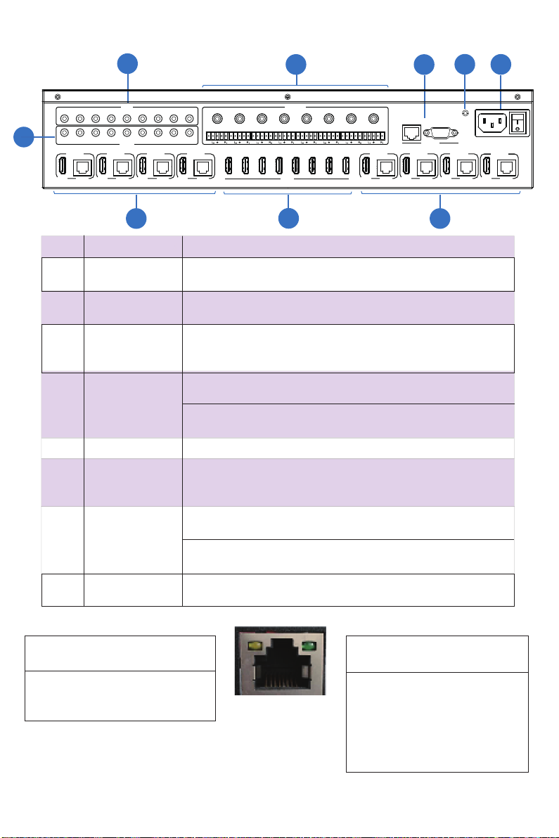
This 18Gbps 8x8 HDBaseT(150M) Matrix can connect 8 HDMI sources to 16 displays. It
features 8 HDBaseT CAT cable outputs and 8 mirrored HDMI outputs. HDBaseT outputs
can extend video transmission distance up to 492ft / 150m @ 1080P or 4K60 4:4:4 up to
394ft/120m via a single Cat 5e/6/6a cable using the best YLVXDOO\ORVVOHVVlow latency
Display Stream Compression (DSC) technology. HDR, HDR10, HDR10+, Dolby Vision &
HLG are also supported. HDMI Dudio is de-embedded to analog and coaxial audio outputs.
Each HDMI output supports 4K2K to 1080P downscalLQJ functionality. Advanced EDID &
CEC are supported via the built-in web interface.
The product supports IR routing. The IR signal is a one-to-one control at the Matrix end,
but the IR signal follows HDMI video channel at the HDBaseT Receiver end.
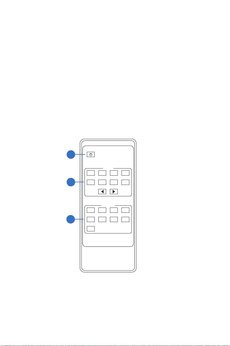
It provides an intuitive set of front panel controls with an OLED screen and supports control
via front panel buttons, IR remote, RS-232, LAN, and Web GUI.
3rd Party control drivers are also available for popular control systems.
HDMI 2.0b, HDCP 2.2 and HDCP 1.x compliant
Video resolution up to 4K2K@60Hz (YUV 4:4:4) on all HDMI & HDBaseT ports
8 HDMI inputs, 8 HDMI & 8 HDBaseT mirrored outputs
HDMI ports transmit 18Gbps lossless uncompressed video bandwidth
Supports 18Gbps visually lossless DSC compressed HDBaseT signal transmission
SupportV4K->1080P Down Scaler for each output port
HDR, HDR10, HDR10+, Dolby Vision, HLG are supported
HDBaseT output can extend video transmission distance up to 492ft / 150m for 1080P
or 394ft / 120m for 4K2K via a single Cat 5e/6/7 cable
HDMI audio pass-through up to 7.1CH HD audio (LPCM, Dolby TrueHD and DTS-HD
Master Audio)
SupportVIR matrix routing
Audio de-embeddLQJ is supported via analog and coax ports
Advanced EDID management and CEC control are supported
24V POC on all HDBaseT ports
2U rack mounted design with front panel OLED display
Control via front panel buttons, IR remote, RS-232, LAN and Web GUI
2. Features
www.phdsolutions.co Page 1 of 34
Display Stream Compression (DSC) is a VESA-developed low-latency compression algorithm.
it is the best visually lossless compression format available supporting color depth up to 16 bits,
with lightweight 2:1 to 3.1 compression ratios.
**

3. Package Contents
ʒ1 x 18Gbps 8x8 HDBaseT(150M) Matrix
ʓ8 x HDBaseT Receiver
ʔ1 x Matrix IR Remote
ʕ1 x 100~240V AC 50/60Hz Power cable
ʖ1 x RS-232 serial cable (1.5 meters, male to female head)
ʗ8 x 3-pin Phoenix Connector & 4 x 5-pin Phoenix Connector
ʘ9 x IR Blaster cable (1.5 meters)
ʙ9 x IR Receiver cable (1.5 meters)
ʚ18 x Mounting Ear (Matrix and Receiver)
ʛ1x User Manual
4. Specifications
7HFKQLFDO
HDCP Compliance HDCP 2.2 and HDCP 1.x
Video Bandwidth 18Gbps
Video Resolution Up to 4K2K@50/60Hz (4:4:4)
Color Space RGB 4:4:4, YCbCr 4:4:4/4:2:2/4:2:0
Color Depth
8-bit, 10-bit, 12-bit (1080p@60Hz)
8-bit (4K2K@60Hz YUV4:4:4)
8-bit,10-bit,12-bit (4K2K@60Hz YCbCr 4:2:2/4:2:0)
HDMI Audio Formats
LPCM 2.0/2.1/5.1/6.1/7.1, Dolby Digital, Dolby TrueHD,
Dolby Digital Plus(DD+), DTS-ES, DTS HD Master,
DTS HD-HRA, DTS-X
Coax Audio Formats PCM 2.0, Dolby Digital / Plus, DTS 2.0/5.1
Analog Balanced
Audio Formats PCM2.0CH
SNR >90dB
ESD Protection Human-body Model:
±8kV (Air-gap discharge) , ±4kV (Contact discharge)
Vmax 2Vrms
www.phdsolutions.co Page 2 of 34
HDMI Compliance HDMI 2.0b
HDR HDR10, HDR10+, Dolby Vision, HLG
Crosstalk >80dB
THD+N Ratio <0.1%(V_max)0.001%~0.01%(V_best)
Frequency Response 20Hz~20kHz ±0.5dB

5HVROXWLRQ'LVWDQFH
HDBaseT Receiver
0HFKDQLFDO
Housing Metal Enclosure
Color Black
Dimensions Matrix: 440mm (W) × 374mm (D) × 88.6mm (H)
Receiver: 140mm (W) x 65mm (W) x 18mm (W)
Weight Matrix: 6.54Kg, Receiver: 155g
Power Supply AC 100 - 240V 50/60Hz
Power Consumption 125W (Max)
0°C ~ 40°C / 32°F ~ 104°F
-20°C ~ 60°C / -4°F ~ 140°F
Operating Temperature
Storage Temperature
Relative Humidity 20~90% RH (non-condensing)
&RQQHFWLRQ
Matrix
.
)HHW0HWHUV
.
)HHW0HWHUV
HDMI IN / OUT 32ft / 10M16ft / 5M
The use of “Premium High Speed HDMI” cable is highly recommended.
3
)HHW0HWHUV
50ft / 15M
CAT5e/6/7
5HVROXWLRQ&DEOHOHQJWK
www.phdsolutions.co Page 3 of 34
Input: 1 x HDBT IN [RJ45, 8-pin female]
Outputs: 1 x HDMI Type A [19-pin female]
1 x AUDIO OUT [3.5mm Stereo Mini-jack]
Controls: 1 x IR IN [3.5mm Stereo Mini-jack]
1 x IR OUT [3.5mm Stereo Mini-jack]
1 x RS-232 [3-pin Phoenix connector]
1 x SERVICE [Mini-USB, Update port]
Inputs: 8 x HDMI Type A [19-pin female]
Outputs: 8 x HDMI Type A [19-pin female]
8 × HDBaseT port [RJ45]
8 × Coaxial audio [5&$]
8 × balanced analog audio [5-pin PhoenixFRQQHFWRU@
Controls: 9 x IR IN [3.5mm Stereo Mini-jack]
9 x IR OUT [3.5mm Stereo Mini-jack]
1 × TCP/IP [RJ45]
1 × RS-232 [D-Sub 9]
ft / 10M
3Feet / Meters.
492ft / 150M

5. Operation Controls and Functions
5.1 Matrix
)URQW3DQHO
www.phdsolutions.co Page 4 of 34
12 1DPH )XQFWLRQ'HVFULSWLRQ
1 OLED screen
2
Display matrix switching status, input / output port, EDID,
Baud rate, IP Address.
3OUTPUT /
INPUT buttons
You need to press an output button (1~8) first and then
press an input button (1~8) to select the corresponding
input source for the output port.
4MENU / ENTER
/ UP/DOWN
ʒ(','VHWWLQJ On the initial OLED display screen, press
“MENU” button to enter “Select EDID” interface, press
“UP/DOWN” button to select the required EDID, and press
the “ENTER” button to enter “Copy to Input:” interface. Then
press “UP/DOWN” button to select the input port you
need to set, and press “ENTER” button again to confirm.
ʓ%DXGUDWHVHWWLQJOn the initial OLED display screen,
press “MENU” button twice to enter “SELECT BAUD” interface,
and press “UP/DOWN” button to select the required Baud
rate, finally press the “ENTER” button to confirm the setting.
ʔ,3$GGUHVV&KHFNOn the initial OLED display screen,
press “MENU” button three times to enter the IP interface
and check the current IP address, then press “UP/DOWN”
button to switch DHCP ON/OFF, finally press the “ENTER”
button to confirm the setting.
Pressing the “MENU” button again will return to the initial
OLED display status.
Power LED The LED will illuminate in green when the product is working
normally, and red when the product is on standby.
5 POWER button
6
Press and hold the POWER button for 3 seconds to enter
the standby mode, then press the button again to wake up
the device.
LOCK button 3UHVVWKH/2&.EXWWRQWRORFNIURQWSDQHOEXWWRQV
H[FOXGLQJWKHSRZHUEXWWRQ3UHVVDJDLQWRXQORFN
7
IR Window IR receiver window, it only receives the IR remote signal
from this product.
1 2 3 4
1 2 3 4
5 6 7
5 6 7
8
8
MENU UP
DOWNENTER
POWER
LOCK
OUTPUT
INPUT

5HDU3DQHO
1R 1DPH )XQFWLRQ'HVFULSWLRQ
1
INPUT (1-8)
ports
HDMI input ports, connect to HDMI source device such
as DPHGLDSOD\HU or JDPHFRQVROH with an HDMI cable.
2
OUTPUT (1-8)
ports HDBT mirrored output ports, connect to HDBaseT Receiver
via CAT cable.
HDMI output ports, connect to HDMI display device such as
TV or monitor with an HDMI cable.
3
Connect to DQIR receiver cable, the IR receive signal will
emit to the “IR OUT” port of the HDBaseT Receiver.
Connect to DQIR blaster cable, the IR emit signal is from
the “IR IN” port of the HDBaseT Receiver.
TCP/IP: The link port for TCP/IP control. Connect to an
active Ethernet link with an RJ45 cable.
RS-232: Command control port. Connect to a PC or control
system with a D-Sub 9-pin cable to control the Matrix.
GND Connect the housing to the groundHDUWK.
POWER input
Power port: Connect to 100~240V AC 50/60Hz power
cable.
Power switch: Press the switch to turn on/off the power.
ƒIlluminating: Matrix and HDBaseT
Receiver FRQQHFWLRQVWDWXVLVJRRG
ƒ)ODVKLQJMatrix and HDBaseT
Receiver FRQQHFWLRQVWDWXVLVSRRU
ƒ,OOXPLQDWLQJ+'0,VLJQDOZLWK+'&3
ƒ)ODVKLQJ+'0,VLJQDOZLWKRXW+'&3
ƒ'DUN1R+'0,VLJQDO
Data Signal
Indicator Lamp
ɟ
ɟ
AUDIO OUT
(1-8) ports
groups of coaxial and balanced analog audio mirrored
output ports. AUDIO OUT (1-8) follows the video output of
OUTPUT (1-8) ports.
5
6
7
8
IR IN (1~8/
ALL) ports
4
IR OUT (1~8/
ALL) ports
CONTROL ports
Video (OUT)
www.phdsolutions.co Page 5 of 34
CONTROL
100-240V AC 50/60HZ
R+L+ R+L+ R+L+ R+L+ R+L+ R+L+ R+L+ R+L+
1 2 3 4 5 6 7 8 ALL
1 2 3 4 5 6 7 8 ALL
IR IN
IR OUT
OUTPUT 1
HDBT
HDMI HDBT
HDMI
OUTPUT 2
HDBT
HDMI
OUTPUT 3
HDBT
HDMI
OUTPUT 4
HDBT
HDMI
OUTPUT 5
HDBT
HDMI
OUTPUT 6
HDBT
HDMI
OUTPUT 7
HDBT
HDMI
OUTPUT 8
1 2 3 4 5 6 7 8
COAX
1
COAX
2
COAX
3
COAX
4
COAX
5
COAX
6
COAX
7
COAX
8
RS-232TCP/IP
INPUT
AUDIO OUT
Connection Signal
Indicator Lamp

5.2 HDBaseT Receiver Panel
www.phdsolutions.co Page 6 of 34
SERVICE
IR IN IR OUT
HDMI OUT
DC 24V
HDBT IN
AUDIO OUT
'&9$SRZHUVXSSO\LQSXWSRUW1R&RQQHFWLRQ5HTXLUHG
1RWH7KH0DWUL[32&IXQFWLRQZLOOVXSSO\SRZHUWRWKH
UHFHLYHURYHUWKH&$7&DEOHQRSRZHUVXSSO\LVUHTXLUHG
HDMI output port, connect to HDMI display device such as
TV or monitor with HDMI cable.
1DPH )XQFWLRQ'HVFULSWLRQ
Power LED Red LED will be on when the receiver is powered on.
SERVICE port Firmware update port.
DC 24V
HDBT IN
Connection
Signal
Indicator lamp
ƒ,OOXPLQDWLQJ0DWUL[DQG5HFHLYHUFRQQHFWLRQVWDWXVLVJRRG
ƒ)ODVKLQJ0DWUL[DQG5HFHLYHUFRQQHFWLRQVWDWXVLVSRRU
ƒ'DUN0DWUL[DQG5HFHLYHUDUHQRWFRQQHFWHG
Data Signal
Indicator
ƒ ,OOXPLQDWLQJ+'0,VLJQDOZLWK+'&3
ƒ )ODVKLQJ+'0,VLJQDOZLWKRXW+'&3
ƒ 'DUN1R+'0,VLJQDO
HDMI OUT
AUDIO OUT Analog audio output port. The audio is extracted from HDMI
signal.
IR IN Connect to IR receiver cable, the IR receive signal will emit to
the “IR OUT” port of the Matrix.
IR OUT Connect to IR blaster cable, the IR emit signal is from the “IR IN”
port of the Matrix.
RJ45 connector for connecting the HDBT OUTPUT port of
Matrix with a CAT cable.
RS-232
Connect to a PC or control system with a 3-pin phoenix
connector cable to transmit commandVbetween the Matrix and
HDBaseT Receiver.
1R
1
2
3
4
5
6
7
8
9
10
11

www.phdsolutions.co Page 7 of 34
IR Remote
①3RZHURQRU6WDQGE\Power on the Matrix or set it to standby mode.
②,QSXWSelect input source button. Select the last or next input source
button.
③2XWSXWEXWWRQSelect output source button.
$OO Select all output source simultaneously. For example, when you press the “All” buttonand
then press input “1” button, WKHinput “1” source will output to all display devices.
④You need to press the output button first and then press WKHinput button to select the
corresponding input source. For example,
Press Output-X
(X means DQoutput button from 1 to 8 , including “All” button)
Then press Input-Y
(Y means DQinput button from 1 to 8)
+'0,0DWUL[5HPRWH
$OO
2XWSXW
,QSXW

7. IR Control System
The matrix includes multiple options for control and routing of IR signals.
www.phdsolutions.co Page 8 of 34
IMPORTANT: PhD Solutions Infrared matrices and extenders are all 5v
and are NOT compatible with alternative manufacturers Infrared solutions.
Please use the supplied IR (TX) Emitters/blasters & IR (RX) Receivers
supplied with the matrix.
The matrix is a switcher and extender of multiple HDMI signals to multiple HDMI receivers
located remotely, it also passes IR control signals through the IR call-back system to the
matrix and HDMI sources for independent control of connected outputs from input
locations.
7ZRZD\,5&DOOEDFNEHWZHHQPDWUL[6RXUFHVDQGGLVSOD\VIURPPXOWLSOHORFDWLRQV
A key feature of the matrix is bi-directional IR control of the matrix, sources and displays
from different locations. Inputs at the matrix end can be controlled at a display location
and displays can be controlled at the matrix location. This is accomplished by placing a
series of IR (TX) Emitters/blasters on devices to control and IR (RX) Receivers at all the
locations you wish to control from. The IR signal travels both ways via the single Cat5e/6/7
cable connected to the display receiver balun.
Please note that IR transmission method is different from the Matrix end (Local) to the
Display end (remote)

IR control from Matrix end (Local): the IR signal is one-to-one transmission. For example,
the IR IN 1 port signal of the Matrix will emit to IR OUT port of the HDBaseT Receiver 1,
and the IR IN 3 port signal of the Matrix will emit to IR OUT port of the HDBaseT
Receiver 3. It doesn’t follow the video switch to change.
IR IN ALL port signal of the Matrix will emit to all IR OUT ports of HDBaseT receivers
simultaneously. Please see the following connection diagram.
www.phdsolutions.co Page 9 of 34
)LJXUH,5FRQQHFWLRQGLDJUDP0DWUL[HQG
0DWUL[
LAN
LAN
IR Blaster
5HFHLYHU
5HFHLYHU
IR Blaster
CAT 5e/6/7 cable
IR IN IR OUT
HDMI OUT
DC 24V
HDBT IN
AUDIO OUT
IR IN IR OUT
HDMI OUT
DC 24V
HDBT IN
AUDIO OUT
TV 5 remote
LAN
LAN
TV 1
TV 3
CONTROL
100-240V AC 50/60HZ
R+L+ R+L+ R+L+ R+L+ R+L+ R+L+ R+L+ R+L+
1 2 3 4 5 6 7 8 ALL
1 2 3 4 5 6 7 8 ALL
IR IN
IR OUT
OUTPUT 1
HDBT
HDMI HDBT
HDMI
OUTPUT 2
HDBT
HDMI
OUTPUT 3
HDBT
HDMI
OUTPUT 4
HDBT
HDMI
OUTPUT 5
HDBT
HDMI
OUTPUT 6
HDBT
HDMI
OUTPUT 7
HDBT
HDMI
OUTPUT 8
1 2 3 4 5 6 7 8
COAX
1
COAX
2
COAX
3
COAX
4
COAX
5
COAX
6
COAX
7
COAX
8
RS-232TCP/IP
INPUT
AUDIO OUT
TV 1 remote
TV 3 remote
LAN
IR Blaster
5HFHLYHU
CAT 5e/6/7 cable
IR IN IR OUT
HDMI OUT
DC 24V
HDBT IN
AUDIO OUT
LAN
TV 5

,5FRQWUROIURPGLVSOD\ORFDWLRQUHPRWH
Insert the 3.5mm IR (TX) emitter/blaster cables into IR OUTPUT ports at the rear of the
matrix. Place the IR (TX) emitter/blaster over the IR window of the source device you
wish to control.
At the display connect the HDBaseT™ display receiver extender balun to the matrix’s
HDBaseT™ output ports with a suitable CAT cable. Insert the 3.5mm IR (RX) receiver
cable into the IR IN port of HDBT receiver balun.
When the user controls the matrix from the display location via remote control, the matrix
IR OUTPUT follows the HDMI video input source. This means that discrete IR is passed
from the IR (RX) receiver connected to the HDBaseT™ display receiver, down the cat
cable to the matrix and outputted through the IR output ports which are matched to the
corresponding video source selected.
For example, the HDMI output signal on the HDBaseT Receiver 1 is from the HDMI
INPUT 2 port, so IR input signal of the HDBaseT Receiver 1 will emit to IR OUT 2 port of
the Matrix. The HDMI output signal on the HDBaseT Receiver 5 is from the HDMI INPUT 4
port. Then, IR input signal of the HDBaseT Receiver 5 will emit to IR OUT 4 port of the
Matrix etc. Any of HDBaseT Receiver’s IR IN signal can output from IR OUT ALL port of
the Matrix. The ALL output port passes all IR commands received by any of the IR (RX)
receivers connected to HDBaseT™ display receiver baluns.
www.phdsolutions.co Page 10 of 34
)LJXUH,5FRQQHFWLRQGLDJUDP+'%DVH75HFHLYHUHQG
DVD remote
0DWUL[
5HFHLYHU
5HFHLYHU
CAT 5e/6/7 cable
CAT 5e/6/7 cable
IR IN IR OUT
HDMI OUT
DC 24V
HDBT IN
AUDIO OUT
IR IN IR OUT
HDMI OUT
DC 24V
HDBT IN
AUDIO OUT
LAN
LAN
TV 1
TV 3
LAN
LAN
Blu-ray player
remote
DVD
Blu-ray player
CONTROL
100-240V AC 50/60HZ
R+L+ R+L+ R+L+ R+L+ R+L+ R+L+ R+L+ R+L+
1 2 3 4 5 6 7 8 ALL
1 2 3 4 5 6 7 8 ALL
IR IN
IR OUT
OUTPUT 1
HDBT
HDMI HDBT
HDMI
OUTPUT 2
HDBT
HDMI
OUTPUT 3
HDBT
HDMI
OUTPUT 4
HDBT
HDMI
OUTPUT 5
HDBT
HDMI
OUTPUT 6
HDBT
HDMI
OUTPUT 7
HDBT
HDMI
OUTPUT 8
1 2 3 4 5 6 7 8
COAX
1
COAX
2
COAX
3
COAX
4
COAX
5
COAX
6
COAX
7
COAX
8
RS-232TCP/IP
INPUT
AUDIO OUT

,5FRQWUROIURPDUGSDUW\FRQWUROV\VWHP
IMPORTANT: PhD Solutions Infrared matrices and extenders are all 5v and are NOT
compatible with most alternative manufacturers Infrared solutions.
:KHQXVLQJWKLUGSDUW\Y,5FRQWUROVROXWLRQVSOHDVHXVHWKHRSWLRQDO3+'
2372&$%/((2SWRLVRODWHGFDEOHIRU,5FRQYHUVLRQWKHVHDUHDYDLODEOHDVDQ
RSWLRQDODFFHVVRU\IURP\RXUGHDOHU
From the control system’s IR output port plug in the 3.5mm Mono end of the Opto-
isolated cable (Part no. Phd- OPTOCABLE-E) Insert the 3.5mm stereo end into the
required IR INPUT port at the rear of the matrix.
At the display connect the HDBaseT™ display receiver extender balun to the matrix
HDBaseT™ output ports with a suitable CAT cable. Insert the 3.5mm IR (TX) emitter/
blaster cables into the IR OUT port of HDBaseT™ display receiver. Place the IR (TX)
emitter/blaster over the IR window of the display you wish to control
The matrix IR INPUT port passes through IR to the HDMI video output display. This
means that discrete IR is passed from the 3rd party control system to the matrix IR
INPUT Port, down the cat cable to the HDBaseT™ display receiver and out the IR(TX)
emitter/blaster to the display.
IR input routing will work as follows: IR Input 1 corresponds to HDBaseT™ output Port 1,
IR Input 2 corresponds to HDBaseT™ output Port 2, IR Input 3 corresponds to
HDBaseT™ output Port 3. IR Input 4 corresponds to HDBaseT™ output Port 4.
The IR window at the front of the matrix will receive IR matrix switching commands from
the matrix master remote control or from an IR emitter placed over the matrix IR window
connected to a control system.
www.phdsolutions.co Page 11 of 34

8. IR Cable Pin Assignment
IR RECEIVER IR BLASTER
www.phdsolutions.co Page 12 of 34
9. EDID Management
This Matrix has 21 factory defined EDID settings, 2 user-defined EDID modes and 16 copy
EDID modes. You can select defined EDID mode or copy EDID mode to input port through
on-panel button, RS-232 control or Web GUI.
2QSDQHOEXWWRQRSHUDWLRQ On the initial OLED display screen, press “MENU” button to enter
the EDID setting interface, press “UP/DOWN” button to select the required EDID, and press
the “ENTER” button to enter “Copy to Input:” interface. Then press “UP/DOWN” button to select
the input port you need to set, and press “ENTER” button again to confirm this operation.
56FRQWURORSHUDWLRQ Connect the Matrix to PC with a serial cable, then open a Serial
Command tool on PC to send ASCII command “s edid in x from z!” to set EDID. For details,
please refer to “EDID Setting” in the ASCII command list of “11. RS-232 Control Command”.
:HE*8,2SHUDWLRQ Please check the EDID management in the “Input page” of “10. Web
GUI User Guide”.

The defined EDID setting list of the product is shown as below:
www.phdsolutions.co Page 13 of 34
(','0RGH (',''HVFULSWLRQ
1 1080p, Stereo Audio 2.0
2
3
4
5
6
7
1080p, Dolby/DTS 5.1
1080p, HD Audio 7.1
1080i, Stereo Audio 2.0
1080i, HD Audio 7.1
1080i, Dolby/DTS 5.1
8
9
3D, Stereo Audio 2.0
3D, Dolby/DTS 5.1
3D, HD Audio 7.1
10
11
12
13
14
15
16
17
18
4K2K30_444, Stereo Audio 2.0
4K2K30_444, Dolby/DTS 5.1
4K2K30_444, HD Audio 7.1
4K2K60_420, Stereo Audio 2.0
4K2K60_420, Dolby/DTS 5.1
4K2K60_420, HD Audio 7.1
4K2K60_444, Stereo Audio 2.0
4K2K60_444, Dolby/DTS 5.1
4K2K60_444, HD Audio 7.1
20
21
22
23
User define1
User define2
19 4K2K60, Stereo Audio 2.0 HDR
4K2K60, Dolby/DTS 5.1 HDR
4K2K60, HD Audio 7.1HDR
Copy from HDMI OUTPUT 1~8
Copy from HDBT OUTPUT 1~8
24~31
32~39

www.phdsolutions.co Page 14 of 34
10. Web GUI User Guide
The Matrix can be controlled by Web GUI. The operation method is shown as below:
6WHS Get the current IP Address.
The default IP address is 192.168.1.100. You can get the current Matrix IP address in two ways:
7KHILUVWZD\
You can get the IP address via panel buttons. On the initial OLED display, press
“MENU” button three times to enter the IP interface and check the current IP address.
7KHVHFRQGZD\
You can get the IP address via RS-232 control. Send the ASCII command
“ r ipconfig!” through a Serial Command tool, then you’ll get the feedback information as shown
below:
LAN
PC
IP:192.168.61.103 in the above figure is the current Matrix IP address (this IP address is
variable, depending on what the specific machine returns).
)RUWKHGHWDLOVRI56FRQWUROSOHDVHUHIHUWR³56&RQWURO&RPPDQG´
6WHS Input the current IP address of Matrix into your browser on the PC to enter Web GUI page.
LAN
6WHS Connect the TCP/IP port of the Matrix to a PC with an UTP cable (as shown in the
following figure), and set the IP address of the PC to be in the same network segment with
the Matrix.

www.phdsolutions.co Page 15 of 34
After entering the Web GUI page, there will be a Login page, as shown below:
Select the Username from the list and enter the password. The default passwords are:
Username 8VHU$GPLQ
Password XVHUDGPLQ
After entering the password, click the “LOGIN” button and the following Status page will
appear.
Ŷ 6WDWXV3DJH
The Status page provides basic information about the product model, installed firmware
version and the network settings of the device.

Ŷ 9LGHR3DJH
You can do the following operations on the Video page:
ʒ2XWSXWThe current device’s OUTPUT port. You can select signal source for it.
ʓ,QSXWYou can click the drop-down menu to select signal source for the corresponding
OUTPUT port .
ʔ3UHVHWV1DPHYou can name the current scene with maximum length of 12 characters
(Chinese name is unsupported).
ʕ3UHVHWV6HWYou can restore the settings of the last saved audio-video matrix switching
relationship.
ʖ3UHVHWV6DYHYou can save audio-video matrix switching relationship.
ʗ3UHVHWV&OHDUYou can clear the saved audio-video matrix switching relationship.
Ŷ ,QSXW3DJH
You can do the following operations on the Input page:
ʒ,QSXWVInput channel of the device.
ʓ$FWLYHIt indicates whether the channel is connected to a signal source.
ʔ1DPHThe input channel’s name. You can modify it by entering the corresponding name
(max length: 12 characters) in the input box (Chinese name is unsupported).
ʕ(','You can set the current channel’s EDID. The specific operation is as follows:
www.phdsolutions.co Page 16 of 34

6HW(','IRUWKH8VHU
Click the “Browse” button, then select the bin file. If you select the wrong EDID file, there will
be a prompt, as shown in the following figure:
Make sure to select the correct file, then you can check the name of the selected file. Select
“User 1” or “User 2”, then click “Upload”. After successful setting, it will prompt as follows:
'RZQORDGWKH(',')LOHIRUWKH&RUUHVSRQGLQJ,QSXW&KDQQHO
Click the drop-down box of “Select EDID File” to select the corresponding input channel. Then
click “Download” to download the corresponding EDID file.
Ŷ 2XWSXW3DJH
You can do the following operations on the Output page:
ʒ2XWSXWVOutput channel of the device.
ʓ1DPHThe current output channel’s name. You can modify it by entering the corresponding
name (max length: 12 characters) in the input box (Chinese name is unsupported).
ʔ7\SHThe current output channel’s type (HDMI or HDBT).
ʕ&DEOHIt indicates the connection status of output ports. When the output port is connected
to the display, it shows green, otherwise, it shows gray.
ʖ6FDOHU0RGHSet the current output resolution mode.
ʗ6WUHDPTurn on/off the output stream.
www.phdsolutions.co Page 17 of 34
Table of contents
Other PhDsolutions Matrix Switcher manuals

PhDsolutions
PhDsolutions MX-4H4H-4K User manual

PhDsolutions
PhDsolutions MX-2H4H-4K User manual

PhDsolutions
PhDsolutions MXC-P442-HDTL User manual

PhDsolutions
PhDsolutions MXC-U-P882-HDTL-PRO-KIT User manual

PhDsolutions
PhDsolutions MXC-P8X8-HDTE User manual

PhDsolutions
PhDsolutions MXC-UHD-P8X8-HDTE User manual

PhDsolutions
PhDsolutions MXC-U-P442-A-HDTL User manual

PhDsolutions
PhDsolutions MXC-UHD-P8X8-HDTL User manual

PhDsolutions
PhDsolutions MXC-U-P882-HDTL-A User manual

PhDsolutions
PhDsolutions ECO Series User manual