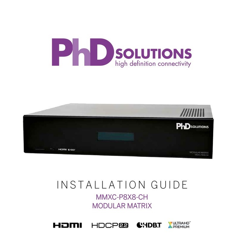
PhDsolutions MXC-U-P882-HDTL-PRO-KIT User manual

8X10 HDBASET MATRIX
INSTALLATION GUIDE
MXC-U-P882-HDTL-PRO-KIT
POWERED BY

2
SAFETY PRECAUTIONS
Please read all instructions before attempting to install or operate
this equipment.
Please keep the following in mind as you unpack and install this
equipment:
• Always follow basic safety precautions to reduce the risk of
re, electrical shock and injury.
• To prevent re or shock hazard, do not expose the unit to rain,
moisture or install this product near water.
• Never spill liquid of any kind on or into this product.
• Never push an object of any kind into this product through any
openings or empty slots in the unit, as you may damage parts
inside the unit.
• Use only the supplied power supply unit (PSU). Do not use the
PSU if it is damaged.
• Do not allow anything to rest on the power cabling or allow any
weight to be placed upon it.
• To protect the unit from overheating, do not block any vents or
openings in the unit housing that provide ventilation and allow
for sufcient space for air to circulate around the unit.
CONCEPTS AND DEFINITIONS
When reading this manual we refer to devices that send video into the matrix as
source devices or sources. Examples of source devices include Blu-Ray players,
Set Top Boxes, Game Consoles and Media Centres.
Devices that receive video from the matrix are called sink devices or sinks.
Examples of these are Ampliers (AVRs) TVs and projectors.

3
IN THE BOX
1x MXC-U-P882-HDTL-PRO
8x10 Matrix Chassis
8x EXC-P100HDTL-RX PoH
70m Class B HDBaseT™ Receivers
8 Button Contextual Remote Control
8x IR Emitters
8x IR Receiver
Rack Mounting Kit
Mains Cable
MANUAL CONTENTS
P4 Cabling Advice
P5 Concept Wiring Guide
P6 Your Matrix
P7 Initial Setup
P8 Connect to the Web Interface
P10 Setting up the Matrix Without an Internet Connection
Technical Specication
P11 Setting up CEC
Third Party Control Drivers
P12 Troubleshooting
P13 Front Panel LED Values
P14 Technical Specications
P15 Warranty Information

4CABLING ADVICE
WHAT IS THE BEST TYPE OF CABLE TO USE?
You can use Cat5e, Cat6, Cat6A or Cat7 with this system.
The minimum cable standard for this system is Cat5e. Slightly greater distances may be achieved by using Cat6A,
or slightly better still with Cat7, which has stricter shielding requirements and reduces potential cross talk between
data pairs.
Whichever network cable type you choose, ensure that the main wiring architecture is solid core, not stranded
patch cabling. Patch cabling can be used for the last few metres of a run (e.g. from a wall plate) but must be avoided
over longer runs as signal transfer over stranded cores is heavily reduced.
The use of pre-made leads is not recommended unless you can be absolutely sure of their construction credentials
(i.e. solid core 568B). Please note that CCA (Copper Clad Aluminium) cable is NOT supported.
SHIELDED CABLES
Unlike other systems, shielded FTP cable is not a stipulation. If, however, you prefer this type of cable please ensure
compatible shielded accessories are used. Failure to terminate cable screen at all points can induce interference
rather than eliminating it.
CABLING BEST PRACTICE
Our best practice policy is to terminate to a wall plate at either end and then use solid core patch cables (usually
it is better to make your own than use pre-made) between the patch panel and the matrix and the wall plate and
HDBaseT™ receiver.
HDBaseT™ WITH PATCH PANELS AND WALL PLATES
If the patch panels are terminated correctly, there is minimal loss of distance. The use of wall plates and patch
panels, however, has the potential to cause increased resistance on the cable if not done correctly, introducing
pinch points for signal transmission, and could reduce advertised transmission lengths.
Instead of using RJ45 wall plates, you can use brush plates to maintain the neat nish.
CONNECTION TERMINATION
Terminate the cabling using RJ45 connectors to the 568B wiring standard. (See diagram)
IMPORTANT
Please note that local building regulations may apply to the installation of cabling in
properties. It is important to check building regulations to guarantee that you are in
accordance with the laws of your territory.

STUDY BEDROOM 3 KITCHEN
SOURCE 1
SOURCE 2
SOURCE 3
SOURCE 4
SOURCE 5
SOURCE 6
SOURCE 7
GYM
INFRARED
IN & OUT
SOURCE 8
BATHROOM
5
CONCEPT WIRING GUIDE
STUDY BEDROOM 3 KITCHEN
SOURCE 1
SOURCE 2
SOURCE 3
SOURCE 4
SOURCE 5
SOURCE 6
SOURCE 7
GYM
INFRARED
IN & OUT
SOURCE 8
BATHROOM

MXC-U-P882-HDTL-PRO
6
IR Receiver and Transmitter Ports Use the supplied IR emitters to link the receivers to the relevant
Infrared ports. LED indicators will light when connected correctly. In ports 1-8 send IR from the matrix to the
sink and in ports numbered 9-10 send IR from the matrix to the active source for that port.
HDBaseT Outputs - Connect your sink devices Connect the appropriate Cat5e or higher grade cable
to each output, these cables should be attached to the receiver at the sink end (TV/amplier etc)
HDMI Outputs - Connect your sink devices Connect the appropriate high speed HDMI cable to each
output, these cables should be attached directly to the sink device
HDMI Inputs - Connect your source devices Connect your source devices via a high speed HDMI cable
Power Use the supplied mains power cable and connect to the chassis. Do not use any other power cables
with this product.
Global IR Used for a control system to be able to see all IR signals from all zones. We recommend using a
PHD-IR-Optocable for connectivity from this port to your control system
Ethernet - Connect to your home router Use a standard Cat5e (or higher grade) cable to provide
internet access to the matrix. This will allow you to receive automatic updates and remote monitoring services
System Health LED Indicator When system is running correctly, the LED will light green
Network LED Indicator When system is connected correctly to the network, the LED will light green
Cloud LED Indicator When system is connected correctly to the cloud, the LED will light green
A
C
B
D
E
F
G
H
I
D
B C
H
J
J
I
A
FGE

7
INITIAL SETUP
1 CONNECT SOURCE DEVICES
Connect your source devices into the input ports using a High Speed HDMI cable or better (not supplied). It is
recommended to connect devices from Input 1 to Input 8, although you can connect them in any order you wish.
2CONNECT SINKS
Sink devices are connected to ports 1-8 via category cable (see cabling advice at the start of this guide) from the
Output port to the supplied receivers. Complete the connection from the receiver to the Sink device (i.e. your TV)
via a HDMI cable.
For Output ports 9 and 10, connect sink devices directly via high speed HDMI cables. Once all connections have
been made, turn the matrix on by connecting the power supply to the mains.
3CONNECT INFRARED
Using the supplied IR pairs, insert the IR Emitter (matte) into the relevant Infrared Out port (for example Out 1 for
Input 1) and attach the bud to the front of the source device, over the IR window. On the sink device (i.e TV) place
the IR Receiver (shiny) in a visable location and plug the end into the RX port on the receiver. Each IR port has an
LED which ashes Red when IR is transmitting and ashes green when IR is being received
4CONNECT RACK EARS
You can mount the system either at the front or back with the supplied rack ears. Simply screw in the supplied M4
screws to connect the rack ears to the matrix.
5NETWORK CONNECTION
The matrix is designed to be on and connected to an active internet connection at all times. It will operate correctly
when not connected to a network (or the internet) but certain functions will not be available. Connect a standard
Ethernet cable between the ethernet port and your router/network switch, cross over cables are not supported.

8CONNECT TO THE WEB INTERFACE
To setup your matrix you need to use the built in web interface. Firstly check your system is connected correctly by
ensuring the network LED is lit green on the front of the matrix.
The web interface can be accessed from any locally connected device via Wi-Fi or a xed wire connection. You can
access the web interface from a mobile, tablet, laptop or desktop PC. Many of the controls in the user interface (UI)
are drag and drop friendly.
GOTOMYMATRIX.COM
You can easily access the web interface by visiting www.gotomymatrix.com into any web browser, on any device,
this will locate the matrix automatically on your local network. (An Android app version is also available)
VIDEO ROUTING
The home page of the UI displays the current routing - devices in blue are active, we have detected they are powered
up*. Select an input with a single click/press and the outputs that this input is routed to will be highlighted. Press
again the same input to restore the normal display.
To change the routing of the matrix, drag the input and drop it on the output you want to send that video to. Once
routing is successful a green success message will display at the top of the screen. If for some reason this routing
cannot be done a red error message will be shown explaining the reason.
You can also change the routing by click on the display icon (or when in user mode) on the output and then
selecting the input from the drop down list. You do not need to click to save changes, the change is immediate.
*Due to certain HDMI limitations this may not be 100% accurate at all times
ACCESS THE ADMIN SETTINGS
Some options are hidden to the user so to access the admin settings go to the Cloud Connection tab and click
on [admin] at the footer of the page to access all options.
LINK MONITORING PORTAL
Keep your system up to date and get notied automatically if a problem occurs by linking your monitoring account,
simply insert your Installer ID in the box under the Cloud Connection tab and it will link to your account. (If you
do not have a monitoring account please contact your sales manager)
RENAMING SINKS
Click on the display icon, enter a new name and click on Save Changes. This name is purely cosmetic and only
used within the web interface. Names must be 13 characters or less and cannot be blank, start with or end with a
space, certain special characters are also not allowed..
9
RENAMING A SOURCE DEVICE
Click on the display icon, enter a new name and click on Save Changes. This name is used by Voice Services
when controlling specic sinks- be careful when naming these if you intend to use voice control to make sure they
are pronounceable.
Names must be 13 characters or less and cannot be blank, start with or end with a space, certain special characters are
also not allowed. Custom names are displayed in the source menu in a CEC enabled TV* and used for voice services.
*where supported.
CONFIGURING NETWORK SETTINGS
By default, the matrix is set to retrieve an IP address via DHCP, you must connect the system to a router or server
that has DHCP enabled. Once initially congured you can modify this setting and switch to a static IP address.
You must ensure that the new settings are correct before saving them as you will no longer be able to access the
matrix if they are incorrect. In order for the internet based functions to operate such as the cloud based monitoring
and gotomymatrix.com facility you must provide at least one valid DNS address. We recommend using the Google
Public DNS address 8.8.8.8 for Primary DNS and 8.8.4.4 for Secondary DNS
DIAGNOSTICS & SETTINGS
Within the web interface you can also check the hardware health under the System Health tab. Here you will
nd the system status, power, connectivity and temperature. You will also nd a HDBaseT link quality test which
will indicate if the HDBaseT link is stable over a sustained period of time.
Under the Routing Control tab you will nd useful options to create custom IR profiles and disable HDMI-CEC
support. Backlight options for the front LEDs can be accessed under the Front Panel tab.
Additional setup information can be found under 'Documentation & Guides' on the installer monitoring portal.

10 ACCESSING THE MATRIX WITHOUT
AN INTERNET CONNECTION
While the matrix works best with an active internet connection it is possible to still congure and operate the
system without one. However to congure the system from its defaults a local network connection is required.
Normal operation of the CEC and IR control systems does not require any network connection, but IP based API
control or Web based controlled does require a persistent network connection.
DISCOVERY TOOL
You can download a discovery tool from your monitoring portal at http://monitoring.phdsolutions.co, this
program will run on Windows 7 or newer only, when run it will scan your network and detect the IP address of your
matrix. If you have multiple matrix systems on the same network, the discovery tool will only display the last found.
If you do have more than one system, it is advised that you disconnect other systems rst.
The discovery tool will display the IP address of the matrix, you can then access the matrix by typing that IP address
into your web browsers address bar.
It is recommended in this mode that you congure the networking to use a static IP address, this allows for you to
bookmark the page easily and return to the web interface easily without needing to run the discovery tool again.
THIRD PARTY CONTROL DRIVERS
You can control the matrix via IR, Serial or our recommended method, TCP/IP. We supply drivers for
common control systems, including Control 4, AMX, Crestron, RTI and Elan. We are constantly improving
our native integration with other platforms, more information and driver downloads are available at
http://monitoring.phdsolutions.co
API REFERENCE
We provide a fully documented API for the matrix, this is available in your monitoring portal
(http://monitoring.phdsolutions.co). You must be logged in to access it.
If you have questions, please speak with your distributor, we are not able to provide programming support directly.

11
SETTING UP CEC
Consumer Electronics Control (CEC) is a built in technology within HDMI, widely supported in modern TVs, AVRs,
Blu-Ray players and Media Centres.
INTRODUCTION
The matrix has built in support for all CEC implementations from different vendors, where possible we have included
additional vendor specic support to maximise compatibility. That said implementation varies between different
brands and continues to improve, certain features described in this manual may not be available on all makes and
models in your setup. If we can detect that a feature is not supported, this incompatibility will be displayed in the
web interface.
DIFFERENT BRANDS
Common brand names for CEC are, Anynet+ (Samsung), BraviaLink or BraviaSync (Sony), EasyLink (Philips),
SimpLink (LG), VieraLink (Panasonic) Kuro Link (Pioneer) CE-Link and Regza Link (Toshiba), RIHD (Onkyo)
More and more devices are using the common name “HDMI-CEC”, often it is disabled by default, and you may need
to enable it in the settings menu before continuing. (Consult the manual for your source or sink device on how to
do this)
HOW IT WORKS AND SWITCHING SOURCES
Depending on the TV you are using will depend on exactly which button you press, for example, on a Sony TV you
press the “Sync Menu” button, this brings up a menu, from here select HDMI Device selection and your source
devices are listed, if you have customised their names, these names will be listed.
The order in which they are displayed may change from time to time, there is no ability to specify the sort order of
devices in these lists. In other brands, simply pressing the “Source” button will list all of the devices alongside other
inputs (such as Network or USB media)

12 TROUBLESHOOTING
Should you encounter installation difculties or issues with device communication, the following checklist of
common issues and causes should help resolve your issues. If you still continue to experience issues, please
contact your place of purchase.
NO OR POOR PICTURE QUALITY:
• Connected and powered? Double check all HDMI, Ethernet and power cables are rmly connected into the correct
ports an all devices are correctly powered.
• Cable length? Are you approaching the maximum distance of the cable (70m) if so, adjust the picture quality or
try using an additional extender kit to go further distance. Cables bundled together may cause cross talk and
further degrade signal quality.
• Signal strength? The use of cable joins, stranded patch panels, wall outlands and stranded patch leads as
interconnects between them, can signicantly reduce signal strength. Use solid core straight through connections
wherever possible.
• If you reduce the resolution of the source do you get a picture? If so, this suggests a conicting resolution between
source and display or a bandwidth capacity issue with your cable. Check all inputs and outputs share the same
resolution capabilities.
• Picture ‘snow’ / HD ‘hoise’ signies a failure to fully establish a signal and can often be caused by poorly terminated
RJ45 connectors or excess cable lengths. Ensure your cable is correctly wired to 568B standards.
• Pink or off-colour picture? This could be caused by an invalid EDID or the source device failing to read the EDID
from the matrix. Try re-booting matrix and all source devices to force the re-reading of the EDID.
• Cable quality and condition - HDMI cable/connectors can easily be damaged and the quality of material can vary,
Always use good quality leads and cables and try swapping cables that are known to be working into the solution
to see if this improves your image.
IR CONTROL:
• Are the IR emitters and receivers correctly positioned to allow infrared signals to be transmitted and received?
Emitters should be xed rmly over infrared sensors of sources. Receivers should be attached to displays
ensuring a clear line of sight to the remote control used to operate. Each IR port has an LED, when correctly
installed the LED will ash red when IR is transmitting and ashes green when IR is being received
• Is your remote control powered and sending a signal? As IR is invisible to the naked eye, check your remote is
transmitting a signal by viewing the remote handset sensor though a digital camera/camera phone. The sensor
should ash when a button on the handset is held down.
• IR signal dropout can be experienced due to exterior emissions of infrared radiation. Ensure emitters and receivers
are away from direct sunlight. Halogen lighting and plasma screens may also interfere with IR signals

13
FRONT PANEL LED VALUES
SYSTEM HEALTH LED
• Solid red - Powering on or fault found
• Solid green - System healthy
CLOUD LED:
• Solid red - Not connected to the cloud
• Solid green - Connected to our cloud
NETWORK LED:
• Solid red - No network cable connected
• Flashing yellow - Discovering IP address
• Solid yellow - Have IP but cannot ping router
• Flashing green - Cannot reach internet
• Solid green - Network healthy
REFERENCE CABLE DISTANCES
Cable Type Range Pixel Clock
Rate
Video Data
Rate
Supported
Video
CAT5e/6/7 70 metres <=225 MHz <=5.3 Gbps
(HD Video)
Up to 1080p,
60Hz, 36-bit, 3D
(data rates lower
than 5.3 Gbps or
below 225 MHz
TMDS clock).
35 metres >225 MHz >5.3 Gbps
(Ultra HD Video)
4K2K, 30Hz
video formats

14 MATRIX TECHNICAL DATA
Dimensions (WxHxD): 43 cm / 8.9 cm / 29.5 cm
Material: Smooth textured powder coated steel
Operating Temperature Range: 0 to +35°C (32 to +95°F)
Operating Humidity Range: 5 to 90 % RH (no condensation)
Power Supply: 1 x IEC C14 Inlet - 100-240V 4.0/2.0A 50/60Hz
Power Consumption: Max 2Amps @ 240V
Video Input: 8x HDMI
Clock Speed: Input: 340Mhz, Output: 340Mhz
Video Output: 2x HDMI and 8x HDBaseT™ Class B (Lite)
Colour Supported: 4K/24bit, 1080p/36bit
3D Supported:
Up to 1080/24p - Frame packing/sequential (Blu-ray),
Interlaced stereoscopic
(Satellite/cable broadcasts)
Additional: HDMI 2.0a 3840 x 2160p 60Hz YCC 4:2:0 format pass-through
Encryption: HDCP and HDCP 2.2
Supported Video Resolutions: 720p, 1080i, 1080p (+3D), 4k (30Hz) 4:4:4, 4k (50/60Hz) 4:2:0
Supported Audio Formats:
PCM 2.0, LPCM 2.0, LPCM 5.1, LPCM 6.1, LPCM 7.1,
Dolby Digital 2.0, Dolby Digital 5.1, Dolby Digital EX 6.1,
Dolby Digital Plus 7.1, Dolby TrueHD 5.1, Dolby TrueHD 7.1,
Dolby Atmos 5.1.2, Dolby Atmos 5.1.4, Dolby Atmos 7.1.2,
Dolby Atmos 7.1.4, Dolby Atmos 9.1.2, DTS 5.1,
DTS-HD Master 5.1, DTS-HD Master 7.1, DTS 96/24 5.1,
DTS-ES Discrete 6.1, DTS-ES Matrix 6.1
ESD Protection: ±8kV (Air-gap discharge) ±4 kV (Contact discharge)
Surge Protection: IEC 61000-4-4 (EFT Burst) Level 2, IEC 61000-4-5 (Surge) Level 2
Certication: CE, FCC, RoHS

15
WARRANTY INFORMATION
IMPORTANT INFORMATION ABOUT YOUR RIGHTS AND OBLIGATIONS, AS WELL AS LIMITATIONS AND EXCLUSIONS THAT MAY APPLY TO YOU.
YOUR RIGHTS AND THIS LIMITED WARRANTY
This Limited Warranty gives you specic legal rights. You may also have
other legal rights that vary by state, province or jurisdiction. The disclaimers,
exclusions, and limitations of liability under this Limited Warranty will not
apply to the extent prohibited by applicable law. For a full description of your
legal rights you should refer to the laws applicable in your jurisdiction and you
may wish to contact a relevant consumer advisory service.
1. WHAT THIS LIMITED WARRANTY COVERS; PERIOD OF COVERAGE
PHD Solutions (“PHD Solutions”) warrants to the owner of the enclosed
product that the product contained in this box (“Product”) will be free from
defects in materials and workmanship for a period of three years from the
date of delivery following the original purchase (the “Warranty Period”), or if
this product has been professionally installed, the warranty start date is from
the date your installer purchased the item, not your system commissioning
date. Please check with your installer for their purchase date. If the Product
fails to conform to this Limited Warranty during the Warranty Period, PHD
Solutions will, at its sole discretion, repair or replace any defective Product or
component. Repair or replacement may be made with a new or refurbished
product or components, at PHD Solutions’s sole discretion. If the Product
or a component incorporated within it is no longer available, PHD Solutions
may replace the Product with a similar product of similar function, at PHD
Solutions’s sole discretion. This is your sole and exclusive remedy for
breach of this Limited Warranty. Any Product that has either been repaired
or replaced under this Limited Warranty will be covered by the terms of this
Limited Warranty for the longer of ninety (90) days from the date of delivery
or the remaining Warranty Period. This Limited Warranty is transferable from
the original purchaser to subsequent owners, but the Warranty Period will
not be extended in duration or expanded in coverage for any such transfer.
2. WARRANTY CONDITIONS; HOW TO GET SERVICE IF YOU WANT TO
CLAIM UNDER THIS LIMITED WARRANTY
Before being able to claim under this Limited Warranty, the owner of the
Product must (a) notify PHD Solutions of the intention to claim by emailing
PHD Solutions during the Warranty Period and providing a description of
the alleged failure, and (b) comply with PHD Solutions’s return shipping
instructions, and (c) ship the Product at owner’s cost (except where
prohibited by applicable law) to PHD Solutions for repair or replacement.
PHD Solutions will have no warranty obligations with respect to a returned
Product if it determines, in its reasonable discretion after examination of the
returned Product that the Product is an Ineligible Product (dened below).
PHD Solutions will bear all costs of return shipping to owner, except with
respect to any Ineligible Product, for which owner will bear all shipping costs.
3. WHAT THIS LIMITED WARRANTY DOES NOT COVER
This warranty does not cover the following (collectively “Ineligible Products”):
Products marked as “sample” or sold “AS IS”; or Products that have
been subject to: (a) modications, alterations, tampering, or improper
maintenance or repairs; (b) handling, storage, installation, testing, or use
not in accordance with the Installation Guide or other instructions provided
by PHD Solutions; (c) abuse or misuse of the Product; (d) breakdowns,
uctuations, or interruptions in electric power or the telecommunications
network; or (e) Acts of God, including lightning, re, ood, tornado,
earthquake, or hurricane. This warranty does not cover consumable
parts, including batteries, unless damage is due to defects in materials or
workmanship of the Product, or software (even if packaged or sold with the
product). PHD Solutions recommends that you use only authorized service
providers for maintenance or repair. Unauthorized use of the Product or
software can impair the Product’s performance and may invalidate this
Limited Warranty. PHD Solutions does not warrant that operation of the
Product will be error-free or uninterrupted or that the Product will in every
case process all data correctly.
4. DISCLAIMER OF WARRANTIES
Except as stated above in this limited warranty, and to the maximum extent
permitted by applicable law, PHD Solutions disclaims all express, implied, and
statutory warranties and conditions with respect to the product, including the
implied warranties of merchantability, tness for a particular purpose. To the
maximum extent permitted by applicable law, also limits the duration of any
implied warranties or conditions to the duration of this limited warranty.
5. LIMITATION OF DAMAGES
In addition to the above warranty disclaimers, in no event will PHD Solutions
be liable for any consequential, incidental, exemplary, or special damages,
including any damages for lost data or lost prots, arising from or relating to
this limited warranty or the product, and PHD Solutions’s total cumulative
liability arising from or related to this limited warranty or the product will not
exceed the amount actually paid for the product by the original purchaser.
6. LIMITATION OF LIABILITY
PHD Solutions disclaims all liability of any kind of PHD Solutions’s suppliers.
The PHD Solutions online services (“services”) may provide you information
(“product information”) regarding your products performance and/or
peripherals connected to your product (“product peripherals”). The type
of product peripherals that may be connected to your product may change
from time to time. Without limiting the generality of the disclaimers above,
all product information is provided for your convenience, “as is”, and “as
available”. PHD Solutions does not represent, warrant, or guarantee that
product information will be available, accurate, or reliable. You use all product
information, the services, and the product at your own discretion and risk.
You will be solely responsible for (and PHD Solutions disclaims) any and all
loss, liability, or damages, including to your hvac system, plumbing, home,
product, product peripherals, computer, mobile device, and all other items
and pets in your home, resulting from your use of the product information,
services, or product.
Product information provided by the services is not intended as a substitute
for direct means of obtaining the information.
7. VARIATIONS THAT MIGHT APPLY TO THIS LIMITED WARRANTY
Some jurisdictions do not allow limitations on how long an implied warranty
lasts or exclusions/limitations on incidental or consequential damages, so
some of the limitations set out above may not apply to you
COPYRIGHT NOTICE
No part of this document may be reproduced, transmitted, transcribed, stored in a retrieval system, or any of its part translated into any language or computer
le, in any form or by any means (electronic, mechanical, magnetic, optical, chemical, manual, or otherwise) without express written permission and consent
from PHD Solutions.
Design and specication is subject to change without notice. E&OE.
© Copyright 2017 PHD Solutions. All Rights Reserved.
Version 1.0 - June 2017

www.phdsolutions.co
Table of contents
Other PhDsolutions Matrix Switcher manuals

PhDsolutions
PhDsolutions HDBaseT MXC-4K888-HDT150-KIT User manual

PhDsolutions
PhDsolutions MXC-P442-HDTL User manual

PhDsolutions
PhDsolutions MXC-U-P882-HDTL-A User manual

PhDsolutions
PhDsolutions MXC-P8X8-HDTE User manual

PhDsolutions
PhDsolutions MXC-U-P442-A-HDTL User manual

PhDsolutions
PhDsolutions MX-4H4H-4K User manual

PhDsolutions
PhDsolutions MX-UHD4H2H User manual

PhDsolutions
PhDsolutions MXC-P8X8-HDT User manual

PhDsolutions
PhDsolutions MXC-UHD-P8X8-HDTE User manual

PhDsolutions
PhDsolutions ECO Series User manual