www.phenomenex.com 4
A. Four Key Steps to Protecting the GC Column and
Extending Lifetime
It is important to protect the column and instrument components from exposure
to dirty samples. Non-volatile or high molecular weight components can
contaminate the stationary phase, causing peak resolution, lower accuracy, and
poor column lifetime. Cutting off the damaged portion will usually restore the
column performance, but over time performance will degrade to a point where
the column can no longer be used. If you are experiencing rapid degradation of
column performance, there are several simple ways to help protect your column
and increase lifetime:
1. Ensure Proper Sample Preparation
a.Filter your samples prior to injection with Phenex™syringe filters (see
Appendix A for details).
b.Use Strata®or Strata
™-X* SPE Cartridges to eliminate contaminants (see
Appendix D for details).
2. Use a Guardian™or Z-Guard
a.Guard Columns – Standard Guards. Z-Guard columns are 5 or 10 meter
pieces of deactivated tubing that are connected to an analytical column
using a glass press-fit connector. The tubing acts like a trap for non-
volatile residues that would otherwise damage the stationary phase of your
analytical column.
b.Guardian Integrated Guard Columns. Unlike traditional guard columns,
there is no mechanical connection between the guard and the analytical
column. The result: all the benefits of a guard column without the possibility
of leaks or activity resulting from a faulty connection. Please contact a
Phenomenex GC Specialist for information on the Guardian.
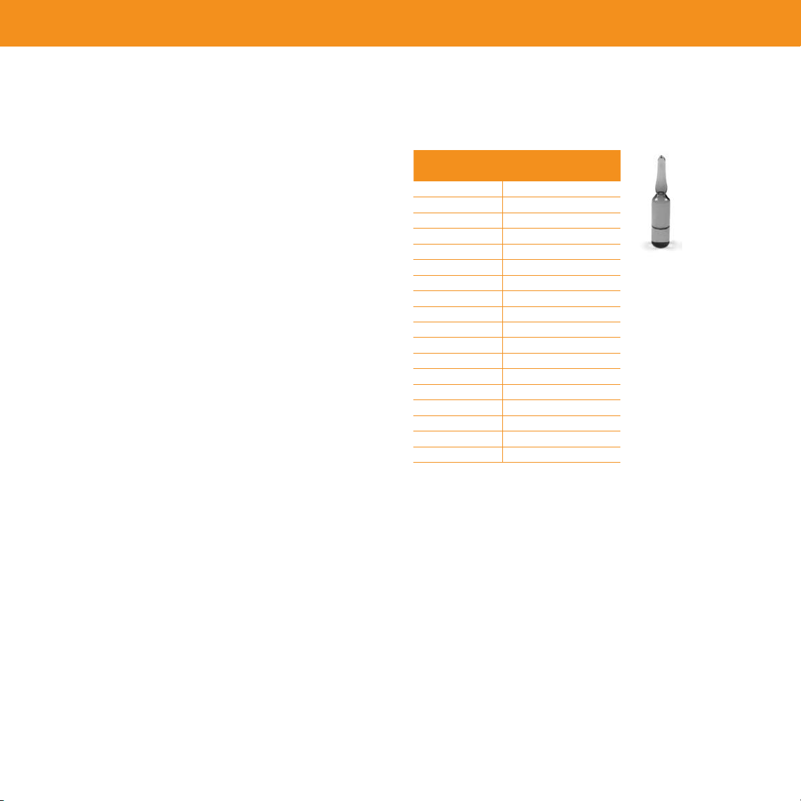
3. Use a Wool Liner
The liner is the first line of defense for the column and the style chosen can make
a big difference in how much contamination gets onto the column. The easiest
thing to do is to add a small amount of silanized glass wool to a liner, which
traps the non-volatile compounds and prevents them from entering the column
(Figure 3). See Appendix B for other recommended GC accessories.
Caution: glass wool can also add activity for acids, bases, and pesticides.
Crushing the glass wool can lead to increased activity, so it is recommended to
purchase pre-packed liners, rather than try to pack your own.
Figure 3. Some liners that are available pre-packed with glass wool or provide
additional column protection:
4. “Baking Out” the Column
The easiest way to reduce column contamination is to add a short, high
temperature bake out at the end of the standard GC method. This bake out helps
remove high boiling contaminants that would otherwise remain in the column
and cause damage. To bake out, the final oven temperature needs to be set
high enough to ensure elution of these compounds, but not so high as to cause
thermal damage. This can be done either isothermally, or more commonly, via a
gradient or ballistic increase until the last components elute from the column.
Caution: NEVER exceed the upper temperature limits of the column. DO NOT
exceed more than 15 minutes at the upper isothermal temperature limit specified
for the column.
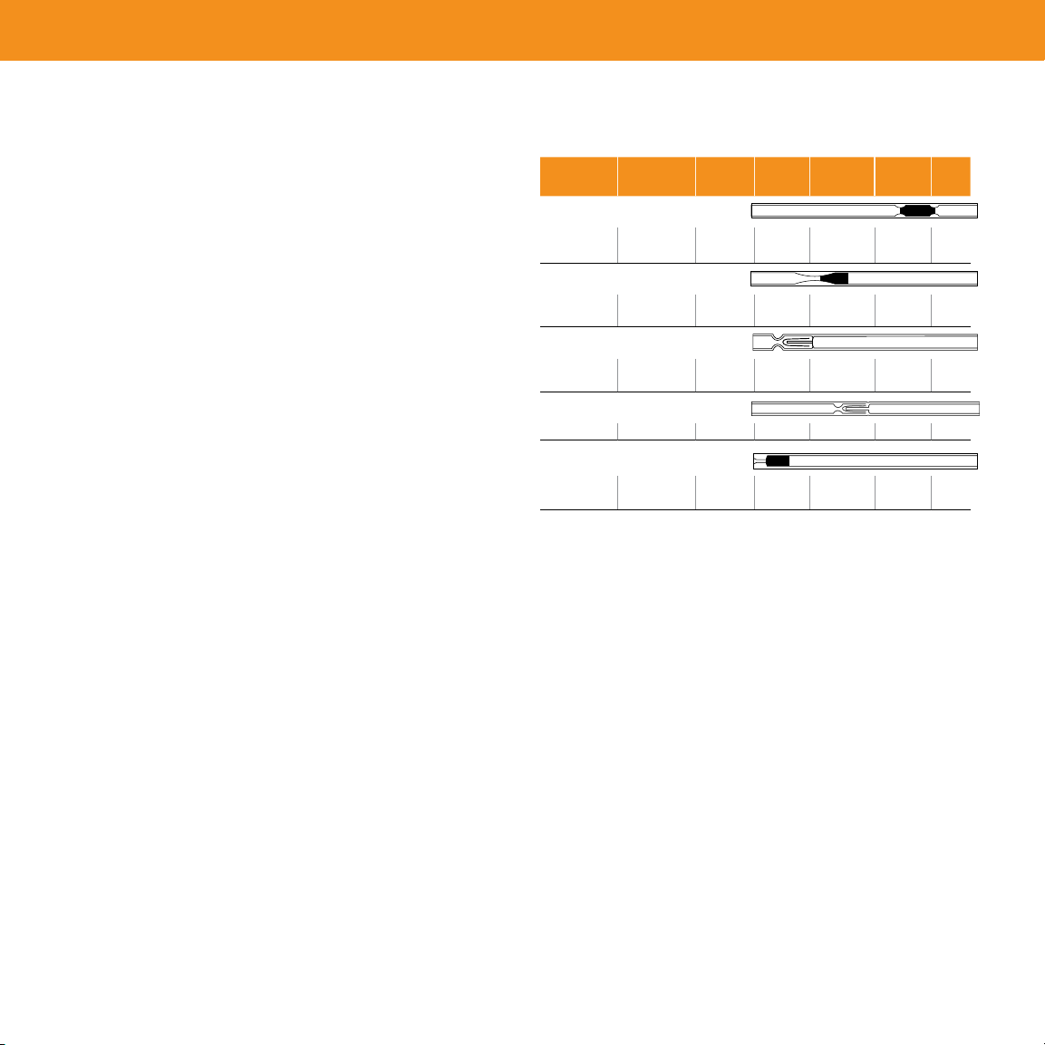
Description
GC Model No.
Dimensions
ID x L x OD
(mm)
Material*
(deactivated)
Quartz Wool
(Y / N) Mfr. No. Part No. Unit
Split/Splitless
5880/5890/6890 4 x 78.5 x 6.3 B (y) Y 210-4004 AG0-7515 5/pk
AG0-7582 25/pk
Split/Splitless, Recessed Gooseneck Liner
5880/5890/6890 4 x 78.5 x 6.45 B (y) Y 5183-4691
5183-4692
AG0-4661
AG0-4662
5/pk
25/pk
Cup Splitter/Split Liner
5880/5890/6890 4 x 78.5 x 6.3 B (n) N 5183-4699 AG0-4647 5/pk
5183-4700 AG0-4648 25/pk
Cup Splitter/Split Liner
AutoSystem™3.5 x 100 x 5 B (n) N 0330-5181 AG0-4663 5/pk
Splitless Single Taper/Liner
5880/5890/6890 4 x 78.5 x 6.45 B (y) Y 5183-4693
5183-4694
AG0-4657
AG0-4658
5/pk
25/pk
* B = Borosilicate; Deactivated = Yes (y) or No (n)
GC Hints and Tips
*Strata-X is patented by Phenomenex, Inc.