Phihong POE62U-560G User manual

Revision 4/26/2018
WWW.PHIHONG.COM
60W Power over Ethernet Waterproof
Passive PoE Single Port Injector for Outdoor Application
Features
•DC Good LED
•Non-Vented Case with Mounting
Bracket
•Gigabit Compatible
•Full Protection OCP, OVP
•IP67 Rating (Waterproof)
•1 Year Warranty
•-40 to +60°C Temperature Range
•Optional Cable Glands for Waterproof
Operation (sold separately)
•Up to 90W w/Derated Temperature.
Applications
•Outdoor Security Cameras
•Outdoor Emergency Lighting
•Outdoor Wireless Access Points
Safety Approvals
•cUL/UL
•CE
Mechanical Characteristics (without Mounting Bracket)
•Length: 252.1mm (9.93in)
•Height: 78mm (3.07in)
•Width: 176mm (6.93in)
•Weight: 1.7Kg (3.75lb)
Mechanical Characteristics (with Mounting Bracket)
•Length: 300mm (11.81in)
•Height: 82mm (3.23)
•Width: 184mm (7.24in)
•Weight: 2.83kg (6.24lb)
Output Specifications
Notes: (1) Consult factory for availability
Phihong is not responsible for any error, and reserves the right to make changes without notice. Please visit our website at www.phihong.com for
the most up-to-date specifications and contact information.
Model
DC Output
Voltage
Load
Regulation
Min.
Max.
Line
Load
POE62U-560G1
56V
0A
1.07A
54-57Vdc under all conditions

POE62U Characteristics
WWW.PHIHONG.COM
INPUT:
AC Input Voltage Range
90 to 264VAC
AC Input Voltage Rating
100 to 240VAC
AC Input Current
2.5A (RMS) and 90VAC at maximum load
1.2A (RMS) and 240VAC at maximum load
AC Input Frequency
47 to 63Hz
Leakage Current
3.5mA for 254VAC, 50Hz
Max Inrush Current
50A for 115VAC at maximum load
75A for 230VAC at maximum load
OUTPUT:
Total Output Power
60W over 4 pairs at 60C
75W over 4 pairs at 50C
90W over 4 pairs at 40C
Ripple and Regulation
300mV maximum
Efficiency
70% (typical) at maximum load, and
120VAC 60Hz
ENVIRONMENTAL:
Temperature
Operation -40 to +60°C
Non-operation -40 to +85°C
Humidity
Operation 5 to 90%
EMI
FCC Part 15 Class B
EN55022 Class B
Isolation Test
Primary to Secondary: 4242 VDC for 1
minute, 10mA
Primary to Field Ground: 2121VDC for 1
minute, 10mA
Output to Field Ground: 2121VDC for 1
minute, 10mA
Immunity
ESD: IEC61000-4-2 Level 3
RS: IEC61000-4-3 Level 3
EFT: IEC61000-4-4 Level 2
Surge: IEC61000-4-5 Level 3
CS: IEC61000-4-6 Level 3
Voltage Dips IEC61000-4-11
Harmonic: EN61000-3-2 Class A
Insulation Resistance
Primary to Secondary: >10M OHM
500VDC
Primary to Field Ground: >10M OHM
500VDC
FEATURES:
Over Voltage/Current, Short Circuit
Protection
The output can be shorted permanently
without damage
Indicators
LED 1: DC Good
Input Connector
3 pin terminal block with M3.5 screw
terminal; for appropriate connection use
minimum 14AWG wire and M3.5 spade lug
Output PoE Connector
RJ45
Output PoE Connection
+pins 3, 6, 4, 5 / -pins 1, 2, 7, 8

POE62U Characteristics
WWW.PHIHONG.COM
Input/Output Case Ports
3 ¾ NPT holes compatible with standard ¾
NPT conduit piping or Phihong wire gland
PGLAND750 with fully waterproof AC and
RJ45 cables.
Network Switch
Network Switch must be Environment Rated
B as per paragraph 33.4.1.1 of the
IEEE802.3at standard.
POE62U Dimension Diagram unit:mm
Single Cable Gland - PGLAND750* Dimension Diagram unit:mm
Double Cable Gland - PGLAND750-2* Dimension Diagram unit:mm
Note *: Cable Glands are sold separately

Safety Procedures –General Precautions
WWW.PHIHONG.COM
General - Please read the following precautions carefully before installing and connecting the
system to a power source.
Note –Only qualified and trained service personnel (in accordance with IEC 60950 and AS/NZS
3260) should install, replace, or service the equipment. Install the system in accordance with
Country, National or to the U.S. National Electric Code if you are in the United States.
Precautions:
1. The building facilities in which the product will be used must provide Isolation to the main
AC Input connector. This connection requires a fuse or circuit breaker no larger than 20A for
120 VAC (U.S.A.) or 16A, 230 VAC (international). The building facilities must protect the
POE62U Power injector from over current or short-circuits.
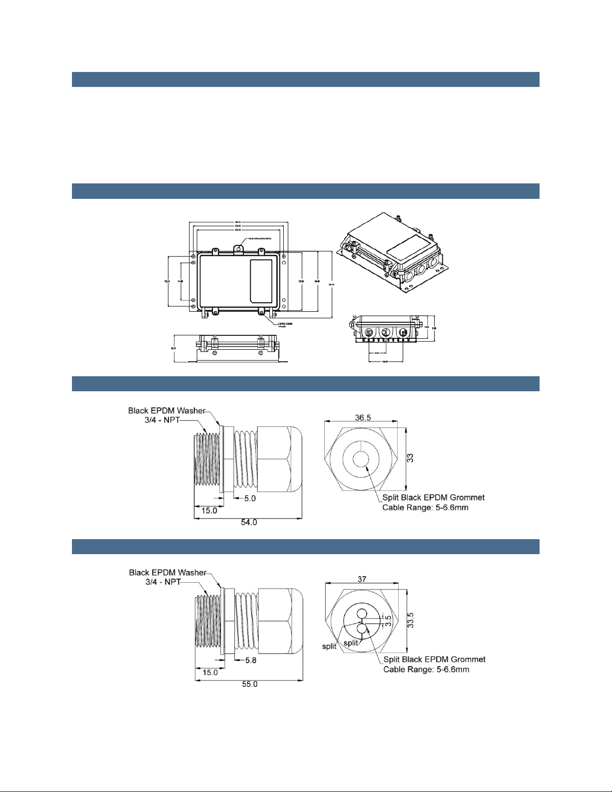
2. The POE62U power injector enclosure is IP67 tested which provides degrees of protection
against access to hazardous parts, dust and against ingress of water. To ensure protection
against ingress of water, torque captive screws (4 places) in an “X” pattern to > 27 inch
pound. –Only qualified service personal should install, replace or service this equipment.
Before connecting, visit “www.phihong.com” for the latest up to date specification and
contact information.
3. The POE62U power injector enclosure must be mounted vertically but not orientation
limited. The enclosure is provided with a steel 2mm thick zinc plated mounting bracket.
When mounting utilize the holes in the mounting bracket plate (10mm holes) 8 places. The
preferred method of mounting is to a vertical 4 inch or 6 inch pole using 2”3/8 x 16” U-
bolts. If mounting on a flat surface, to sheetrock or wood and or others material, use 4 M6
fasteners. Other fasteners may be used, but hardware must be sized to support 4-5 times the
weight of the unit.
4. The POE62U power injector enclosure has 3 threaded (¾ NPT) openings to accommodate
waterproof / water tight conduit and or cable glands. WARNING: To ensure protection
against ingress of water, the connection(s) of the conduit and or cable glands are threaded
with Teflon tape all the way through the holes in an enclosure wall.
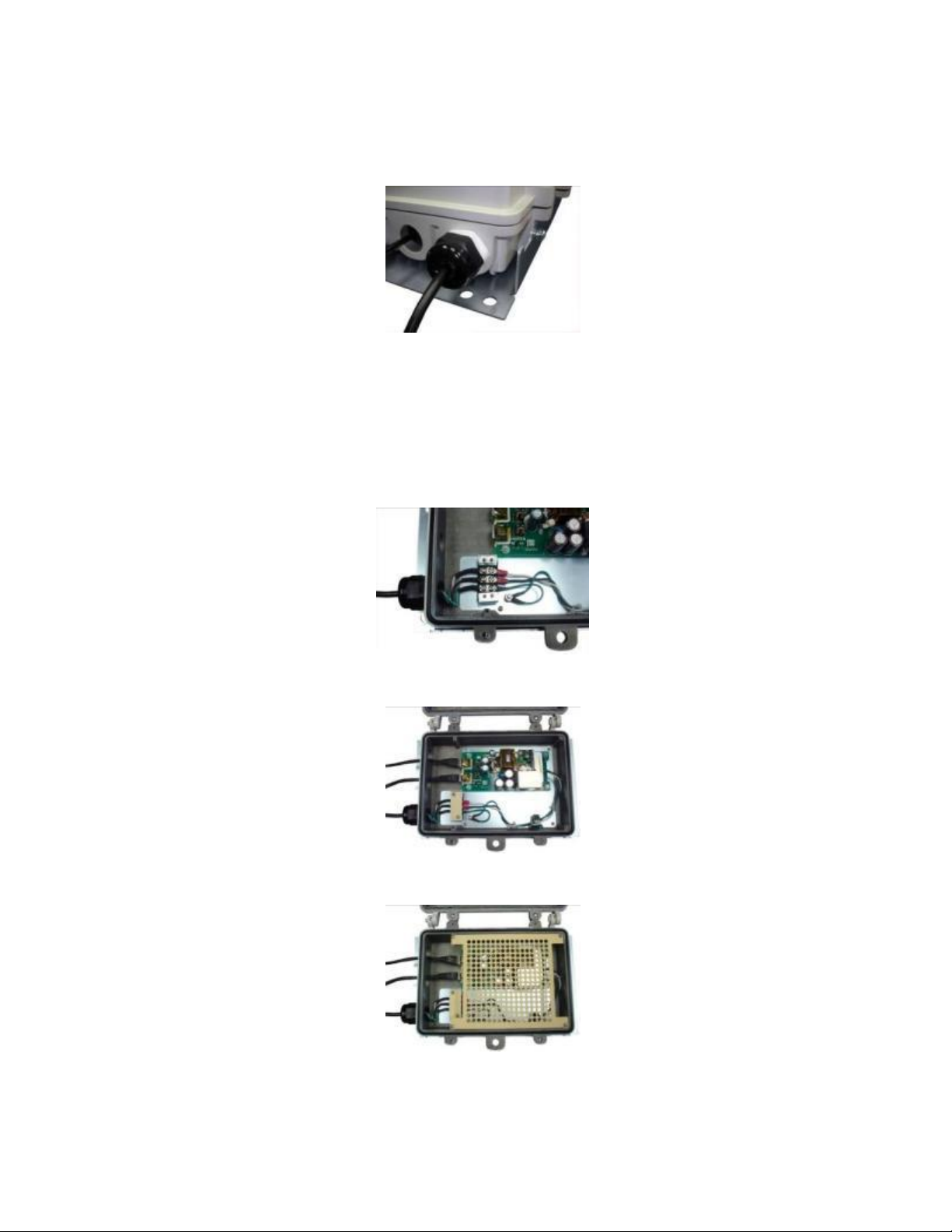
5. The POE62U power injector AC input connector (located inside enclosure) is a 3 pin terminal
block 9.5mm, rated 20 A, 250 V, with M3.5 Nickel Plated steel screws. The incoming 3
wire/cable must be minimum 14AWG and or in accordance with Country, National Electric
Code.
6. The POE62U Power injector consists of “Data & Power” ports. The ports are providing
TNV-1 outputs. The ports use RJ-45 data sockets. Do not connect telephone cables into
these ports. Only RJ-45 data cables with waterproof / water tight connections may be
connected to these sockets.
7. To prevent the POE62U Power injector from overheating, do not operate the product in an
area that exceeds the maximum recommended ambient temperature of -40 ºC to +60 ºC.

8. Do not work on the POE62U Power injector or connect or disconnect cables, during periods
of lightning activity.
9. The AC connector wire combination must be accessible at all times, as it serves as the main
disconnect device to the product.
10. Before servicing the product, always disconnect the product from its AC source.
11. Equipment is for Pollution degree 2 Environment.
12. Disposal of this product should abide by all appropriate National laws and regulations.
Installation Instructions
1) The unit is packaged fully closed with the mounting bracket pre-installed; remove from
packaging and loosen the four captive screws located at the top of the midspan so that the lid
can be lifted easily.
2) Using a Philips screwdriver, remove the four screws holding the protective covering for
the PC Board, and the two screws for the protective covering over the AC terminal block.
3) Connect cable glands (PGLAND750) or ¾ NPT conduit piping to the face of the
midspan. Ensure that connectors are fully installed to guarantee waterproof operation.

4) To better enable waterproof operation it is recommended that installers use Teflon tape to
cover threads before installation. Users may also wish to use silicon sealant to further protect
from ingress of liquid.
5) Thread outdoor rated waterproof AC cable (must comply with all local, national and
country electrical codes) from source through piping/gland to the terminal block. The AC cable
will need to be a minimum of 14AWG and terminated with M3.5 spade lugs. Pair and secure
ground, line, and neutral to the appropriate positions on the three pin terminal block and
reattach the protective covering. Note: if using the cable gland PGLAND750, the outer seal nut
needs to be fully tightened to close rubber seal to protect against ingress of water.
6) Using waterproof outdoor rated Cat5e Ethernet cable, thread through cable glands or
conduit piping to the appropriate RJ45 connector and ensure each portal is properly sealed.
7) Reattach the protective covering over the PC board and terminal blocks and re-close the
lid. Ensure that the four captive screws are fully tightened before operation can commence.
Other Phihong Laboratory Equipment manuals
Popular Laboratory Equipment manuals by other brands

Thermo Scientific
Thermo Scientific F1-ClipTip Instructions for use

Daihan Scientific
Daihan Scientific WiseSpin CF-10 user manual

DH Lifelabs
DH Lifelabs Aaira Surface ASE-00WH07 quick start guide

Fagron
Fagron CapsiCards operating manual

Xylem
Xylem SI Analytics TitroLine 5000 operating manual

Okolab
Okolab H301-PI-736-160x110 user manual

Olympus
Olympus SZX-RFL3 instructions

Enraf Nonius
Enraf Nonius Packheater operating instructions

Peak Scientific
Peak Scientific TOC 1500 user manual

IT-IS Life Science
IT-IS Life Science MyGo Pro user guide

Hach
Hach TitraLab AT1000 Series Basic user manual

akrometrix
akrometrix Table Top Shadow Moire user manual