6
Edge mode:
::
:
Edge mode is suitable for switches that normally use a fixed position. When the
switch is held down, it can control Relay1 or Relay2 to be ON. When the switch is
held up, it can control Relay1 or Relay2 to OFF.
Pulse mode:
::
:
The Pulse mode is suitable for releasing the automatic pop-up switch. Pressing the
hand and then releasing the switch can toggle the Relay1 or Relay2 to ON (or OFF);
press the hand again to release the switch, and then toggle the Relay1 or Relay2 ON
aga n. OFF state; and so on.
Edge-Toggle mode:
::
:
The Edge-Toggle mode can only be used on switches that are normally fixed positions.
Toggle control of Relay1 or Relay2 is ON (or OFF) each time the switch is pressed
(be ng held or t lted); the hand s sw tched aga n (turned or pressed). , then aga n toggle
the ON/OFF state of Relay1 or Relay2; and so on.
Control switch:
Dongle action directions
RELAY Toggle mode When the switch has a switch, Relay will be anti-
action, ON become OFF, OFF become ON
Pulse mode When the switch is pressed once (Press →
Release),Relay will be anti-action, only press not
released
Edge mode When the switch is switched on, only Relay ON
action, when releasing, only the Relay OFF action
DIMMER Long press When the button is pressed for more than 1 second
and is not released, it is judged as a long press. The
dimmer will start dimming until the button is
released. The dimming will be stopped, and the
state will be stopped at the time of release.
Short press When the key is pressed within 1 second, one press
(press →release), it is judged as a short press. If
the current LEVEL is not 0%, it will be moved to 0%,
and the current LEVEL is 0%, then it will move to the
previous LEVEL.
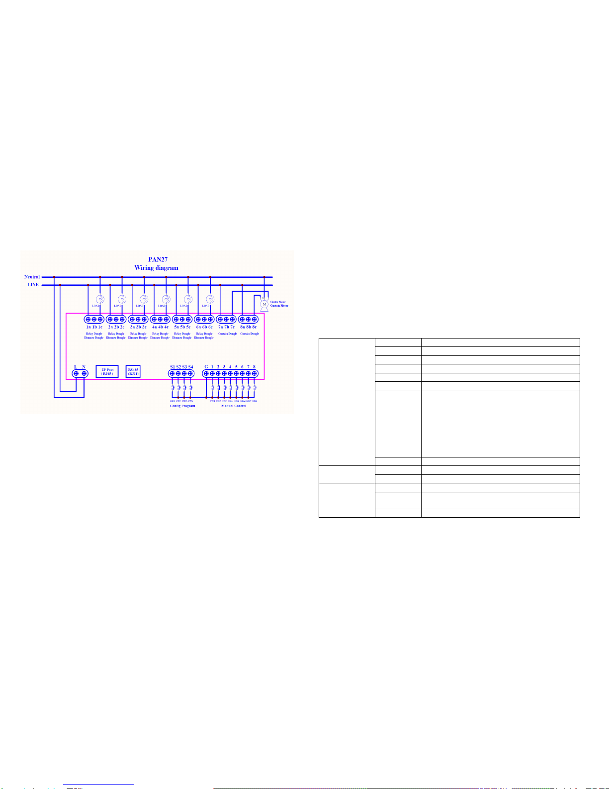
Current Detection:
When the Module is in the normal working mode, it has a load detection function, that
is, detects the power load status of the Module.
When an "overload" condition is detected, the Module switch is immediately set to
“OFF” and the load power is permanently switched off.
In the overload condition, the Module no longer accepts the control (including the signal
of the Module button and the RF control ON), and must wait until the Device releases
the Error state caused by the overload and operates normally.
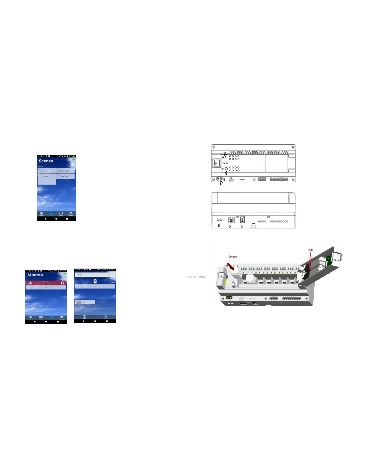
LED indicator:
General mode: When the Module enters the normal working mode, if there is a control
switch or RF command control module, the LED will show the Module state, when
there is electricity conduction, the state is ON green, the state is OFF when the power
is off. red light.
When no Module is installed in this position, the LED indicator is completely off.
POWER signal: When there is a normal power supply, the light is always on, and it
flickers when there is a network connection.
Connection Signal: When the connection status of PAN27 is Ready, the indicator will
keep on, and it will flash when entering the learning.
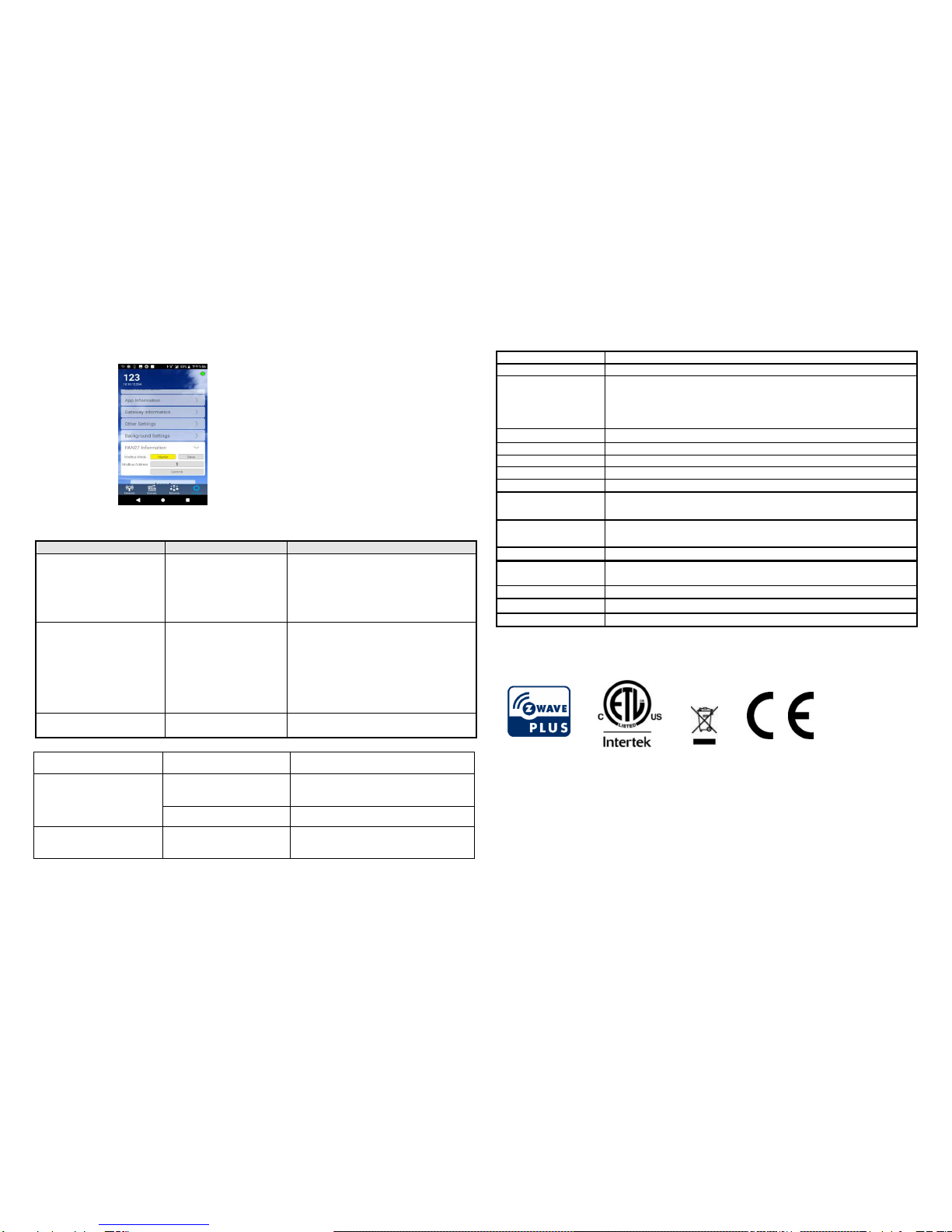
RJ11 (RS485) Control:
Using the MODBUS protocol
The default is master, you can use app be set to slave
When other slaves are connected, they will be automatically detected and include the
device