manuals.online logo
Brands
  1. Home
  2. •
  3. Brands
  4. •
  5. Philips
  6. •
  7. Receiver
  8. •
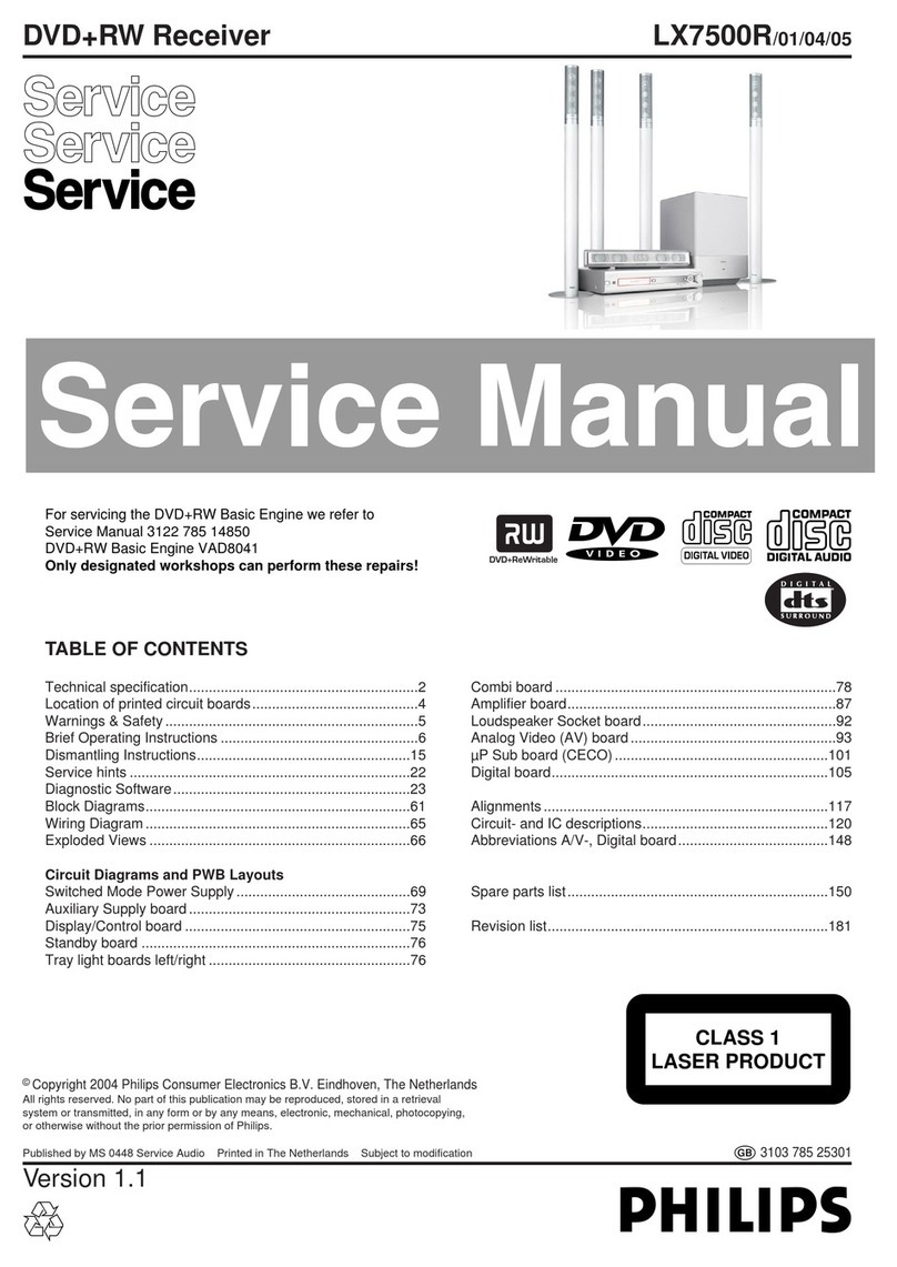
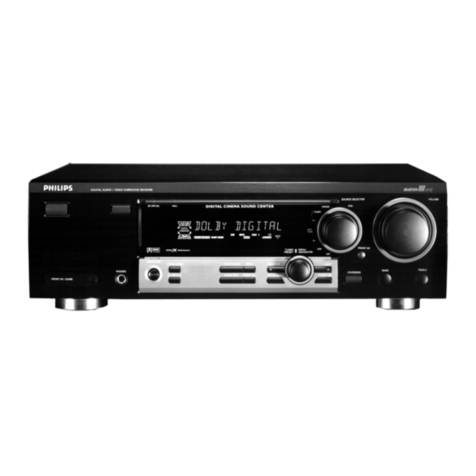
  9. Philips MatchLine FR980 User manual

Philips MatchLine FR980 User manual

Digital
home
cinema
receiver
FR980
FR980/o01
Service
Service
eee
Service
Table
of
Contents
Technical
Spcifications
...........eceseceeretenereeeeteeees
1-1
Circuit
diagraM
PFO4.......ce
ce
ceesseeeseeeseeeeceeesenens
4-8
INStrUCTIONS
FOF
USE
........ccccceeseeseeeeeneeecetenneeneeneeeees
1-2
Printed
circuit
board
PFO4
o......
cc
eeeeeseeeeeeeeeeeees
4-8
Warning
&
Safety
......csscceeseserceseessereeeteesneneneessensees
1-9
Circuit
diagraM
PY04
occ
ccsssseeesscsesesseeesenenees
4-9
Service
Program
.....scsecescseeeteeeeseeeeteeersateerseeteenesens
2-1
Printed
circuit
board
PY04
ou...
ccscsseeeteeerrcetens
4-10
Test
Equipment
required
.........
ce
eeeeeeseeresstseeseeesees
2-2
Printed
circuit
board
PEO4
oes
eceeseeeeeneeeaes
4-11
Alignment
Procedures
.........:ccesereeeseteesseseseteneneeseess
2-2
Circuit
diagram
PEO4
.......cccseseeeseeeeeettereeenneees
4-12
MPEG
decoder
Module
...........::ccescseseeeesseeneetseneeees
2-5
Circuit
diagraM
P704
ou...
ee
ceesseeseeseeseseeeeseesnes
4-13
W/O
Pi
.....eeeeeecesseevesceneessecnenecseeeeeseateensenseesesesaneenss
2-5
Printed
circuit
Doard
P7040...
cece
eetreeeeereeeeeee
4-14
Short
description
.......ccecsecessessssenseseeeeseestensaeeneeeees
2-5
Circuit
diagram
Key
COMPONENTS
........csceeeeteeteteeeeeetetentessceteeeneennenee
2-6
PB04
PP04
PP94
PU94
PW04
P754
.......
eee
4-15
Wiring
GiAGram
..........escceeeeseneteeneceseseeeseeseeteeeneesenenens
3-1
Printed
circuit
board
BlOCK
GIAQIAIM
........eceseeseeseteeeteeeeseentersscnsnerseenseneenes
3-2
PBO4
PP04
PP94
PU94
PW04
P7564
........cseeseee
4-16
Circuit
diagram
P104
uu...
eeeceeseecseeeeserseereenenerseneees
4-1
Printed
circuit
board
P604.......
ee
esseeteeeeeeteeee
4-17
Printed
circuit
board
P104..........ceesesetereeeteeereees
4-2
Circuit
diagram
P604-1/3
Circuit
diagram
PU04
PU5S4
PLO4
......
eee
4-3
Circuit
diagram
P604-2/3
Printed
circuit
board
PU04
PU54
PL94.............
4-4
Circuit
diagram
P604-3/3
Circuit
diagram
PSO4
ou...
cesses
ceeeeerenenetees
4-5
Circuit
diagraM
PCO4
ou...
eects
eeeeeeteenertnetees
Printed
circuit
board
PSO4
........
esses
seeeeeeeeeeee
4-5
Printed
circuit
board
PC04
o......
ec
ceeeeeeeereeeeeee
4-22
Circuit
diagram
PS54
ou...
cee
seeserseeeereeseeeees
4-6
IC
blOCK
GiAQGrAM
ue
eeeeeenecseccesceneeereneseeneneeeeenes
4-23
Printed
circuit
board
PS54
ou...
ce
eeeeeseeerteeeteeeeees
4-6
Exploded
VIGWS
uu...
sccessessessesssecceeneeseneseeesertaenenees
5-1
Circuit
diagram
PLO4
......
seer
se
teereeeseessens
4-7
Mechanical
parts
list
............ccccccssessesecsesesrereeeeeetenes
5-2
Printed
circuit
board
PLO4
......
cece
cess
tee
tteeeeeee
4-7
Electrical
parts
list
..........ccccesssccscscseteeeceeeeneeesees
5-3
Safety
regulations
require
that
the
set
be
restored
to
its
original
condition
and
that
parts
which
are
identical
with
those
specified
be
used.
Copyright
1998
Philips
Consumer
Electronics
B.V!
Eindhoven,
The
Netherlands
All
rights
reserved.
No
part
of
this
publication
may
be
reproduced,
stored
in
a
retrieval
system
or
transmitted,
in
any
form
or
by
any
means,
electronic,
mechanical,
photocopying,
or
otherwise
without
the
prior
permission
of
Philips.
Published
by
MW9808
Service
Disc
Systems
Subject
to
modification
4822
725
26105
é
ee
PHILIPS
1-1
TECHNICAL
SPECIFICATIONS
FM
TUNER
SECTION
Frequency
Range
Usable
Sensitivity
IHF
S/N
Mono
/
Stereo
THD
Mono
/
Stereo
Stereo
Separation
1kHz
ACS
400kHz
image
Rejection
98MHz
Output
Level
1kHz
75kHz
Dev.
AM
TUNER
SECTION
Frequency
Range
Usable
Sensitivity
Loop
S/N
THD
1kHz
30%
Mod
Selectivity
10kHz
AUDIO
SECTION
Power
Output
FrontL/R
20
-
20kz
80hms
Center
20
-
20kHz
80hm
Surround
40
-
20kHz
80hms
THD
Front
L/
R
20
-
20kHz
80hms
Input
Sens
/
Imp
High
Level
L/R
Channel
Crosstalk
1kHz
Freqency
Response
(Analog
Stereo)
-2dB
S/NIHF-A
Dolby
Ch
Separation
1kHz
L/C/
R/S
(AC-3)
Surround
Delay
Tine
VIDEO
SECTION
Input
Sens
/
Imp
Output
Level
/
Imp
Frequency
Response
-1dB
S/N
Crosstalk
Composit
Composit
OTHERS
Mains
Voltage
Mains
Frequency
Backup
initialisation
Dimensions
(WxDxH)
Weight
ACCESSORIES
SUPPLIED
Remote
Control
FM
Feeder
Antenna
AM
Loop
Antenna
Fuse
PCS
98
379
87.5
-
108.0MHz
1.3pnV
/
13.5dBf
76
/
68dB
0.2/0.5%
40dB
60dB
50dB
700mV
520
-
1710kHz
:
10kHz
Step,
531
~
1602
:
9kHz
Step
500nV
50dB
0.5%
25dB
60W
x2
60W
x
1
60W
x
2
0.05%
220mV
/
50kohm
80dB
10
-
50kHz
85dB
60dB
MPEG,
AC-3
:
0
-
15m
Sec
(common)
Pro
Logic
:
15
-
30m
Sec
(relate
to
AC-3
setting)
Other
:
40
-
90m
Sec
1.0Vpp
/
750hm
1.0Vpp
/
750hm
10
-
8MHz
55dB
50dB
110/115
/
220
/
230V
50
/
60Hz
1
Week
Audio
:
Digital
(Coa
x
1)
Video:
DVD
Mode:
MPEG
VOLTAGE
:
230V
OSD:
PAL
SCAN
STEP:
10kHz
439
x
458
x
158mm
13.0kg
RC980FR
+
Batteries,
2
x
AAA
1
x
Ribbon
Type
1x
1x
110V/
115V
(T6.3A)
O8€
86
SOd
DIGITAL
HOME
CINEMA
RECEIVER
-
FR98
CONTENT
INTRODUCTION
Front
panel
SHIPS
»
Front
panel
Rear
panel
1
Power
On/Off
button
1
AM
tuning
switch
2
Night
Antenne
connections
Digital
input
2
AM,
GND,
EM
(coaxial)
3
OPTICAL
Audio
output
4
COAXIAL
3.
TAPE
5
COAXIAL2
Audio
input
Audio
source
selector
4
CD
and
TAPE
6
FM/AM
Audio/Video
input
7
cD
5
VCR,
DVD,AUX
1,TV/SAT
8
TAPE
Audio/Video
output
Tuner
controls
6
VCR
9
Preset
up/down
TY
output
10
Tuning
up/down
7
TV/MONITOR
Sound
control
11
BASS
12
TREBLE
13,
BALANCE
Phone
14
Headphone
jack
Audio/video
source
selector
15
TV/SAT
16
DVD
17
VCR
18
AUX
1
19
AUX
2
Volume
20
Control
up/down
AUX
2
input
a3
WINKO
22
AUDIO
left/right
Pre-amplifier
output
8
FRONT
left/right,
SURROUND
left/right,
CENTER,
SUB-
WOOFER
Remote
control
9
IN
and
OUT
Digital
input
10
COAXIAL],
COAXIAL2
and
OPTICAL
Speaker
output
11
CENTER
left/right,
SURROUND
left/right,
FRONT
left/right
Voltage
selector
12
110V,
115¥,
220V
and
230V
13°
Mains
Ramoata
Cantrnl
LED
indication
A
LEARNING
made
B
TRANSMITTING
mode
Mode
switch
C
Switch
remote
into
NORMAL
operation/USER
defined
or
LEARNING
mode
Source
power
1
Switch
POWER
on/off
of
selected
source
Audio/Video
source
selection
2
TV
3
DVD
4
VCR
5
AUXI
6
AUX2
Audio
source
selection
7
TUNER
8
CD
9
TAPE
Receiver
controls
10
POWER
Off
31
POWER
On
12
SLEEP
Mode
23
NIGHT
switch
(optimal
sound
reproduction
at
low
volume)
24/28
Cursor
Control
(OSD)
and
SELECT
30
On
Screen
Display
(OSD)
with
satus
info
34
Receiver
DISPLAY
on/off
38
MUTE
39
VOLUME
Up
40
VOLUME
Down
41/49.
51)
Numeric
keys
50
MEMORY
enable
for
various
preset
functions
52
Preset
SCAN
Surround
modes
selection
13,
PRO
LOGIC
@
Remote
Control
1
aE
a
rc
ay
ri
a
MONS
8G
jaa
os
cH
od
putisy
1681
Bois
PHILIPS
proceanyaied
Brisbie
FoNtadl
UHCT
14
3
STEREO
15
MOVIE
16
DIGITAL
(MPEG2/Dolby
Digital)
17
MATRIX
18
HALL
19
STEREO
Digital
input
selection
20
OPTICAL
21
COAXI
22,
COAX2
TV
controls
29
MUTE
33
VOLUME
Up
37
VOLUME
Down
Speaker
conrols
31
CHANNEL
selection
32
CHANNEL
Up
36
CHANNEL
Down
35
TEST
Tone
DVD
controls
53
AUDIO
54
Previous
35
Pause/Cursor
Up
56
Next
57
SUBTITLE
58
Search
backward/Cursor
left
59
OK
60
Search
foreward/Cursor
right
61
ANGLE
62
Stop
63
Slow/Cursor
Down
64
Play
65
MENU
66
TITLE
INTRODUCTION
Page
2
©
Safety
precautions
INSTALLATION
‘
Page
3
©
Unpacking
©
Placement
*
Loading
the
batteries
CONNECTIONS
Page
4
©
Connecting
the
power
supply
©
Remote
Control
Bus
©
Digital
inputs
©
Digital
Home
Cinema
speaker
configurations
©
AM
tuning
step
©
Antenna
©
Multisystem
remote
control
OPERATION/GETTING
STARTED
Page
6
*
Switching
on
¢
Receiver
Display
*
OSD
On-Screen
Display
©
Changing
the
TV
broadcast
standard
setting
©
Digital
Home
Cinema
*
Home
Cinema
®
Listening
to
a
different
audio
source
*
Recording
from
a
video
source
©
Night
®
Setting
the
Sleep
timer
©
The
tuner
©
Presetting
stations
©
Auto
presetting
©
Manual
presetting
*
Selecting
a
preset
station
©
Preset
scanning
©
Naming
presets/Station
names
*
Clearing
presets
*
Operation
using
the
OSD
*
[Input
selector
©
Surround
Mode
©
Speaker
level
adjustment
©
Setup
Menu
*
Sleep
Timer
©
Headphones
*
Tone
controls
©
Balance
control
SETUP
~
©
Setting
up
your
Home
Cinema
system
©
Speaker
level
calibration
*
Delay
times
©
Multisystem
remote
control
Page
10
BEFORE
REQUESTING
SERVICE
Page
13
TECHNICAL
SPECIFICATIONS
Page
14
Philips
welcomes
you
to
the
brilliant
new
world
of
Digital
Home
Cinema.
To
the
FR
980,
the
first
Digital
Home
Cinema
receiver,
capable
of
decoding
DVD-Video
as
well
as
other
digital
and
analogue
multichannel
audio
signals,
and
with
five
independent
high-performance
sound
channels.
As
the
control
centre
for
your
Home
Cinema
or
A/V
system,
this
world-standard
receiver
features
multistandard
digital
surround
decoding
and
full
audio
and
video
interconnection
and
remote
control
facilities,
together
with
multivoltage
AC
power
input
and
a
multistandard
On-Screen
Display
output
for
your
TV.
Safety
precautions
Placement
notes
for
cabinet:
To
ensure
proper
ventilation
for
the
amplifier,
do
not
mount
it
in
a
rack
or
locate
it
inside
a
bookshelf.
Note
the
following
precautions:
*
Do
not
insert
objects
into
the
space
underneath
the
amplifier.
©
Do
not
block
the
vents
on
the
top
of
the
amplifier.
©
Keep
the
area
above
the
amplifier
unobstructed
for
about
one
meter.
©
Allow
approximately
20
centimeters
of
space
on
all
sides
of
the
amplifier.
©
Do
not
expose
the
equipment
to
rain
or
moisture.
*
Do
not
remove
the
cover
from
the
equipment.
©
Do
not
push
anything
inside
the
equipment
through
the
ventilation
holes.
®
Do
not
bandle
the
mains
lead
with
wet
bands.
This
Philips
product
has
been
prepared
to
comply
with
the
household
power
and
safety
requirements
that
exist
in
your
area.
On
the
rear
panel,
a
voltage
selector
(4-position)
is
provided.
Be
sure
to
set
the
voltage
selector
to
the
mains
voltage
of
your
area
before
using
the
unit.
ok
L8€
86
SOd
Unpacking
First
check
and
identify
the
contents
of
your
FR
980
receiver
package,
as
listed
below:
©
FR
980
receiver;
Multisystem
remote
control
handset
with
separately-packed
batteries;
Line
fuse
6.3A;
*
User
Manual;
©
Warranty
card.
If
any
item
should
be
damaged
or
missing,
please
inform
your
supplier
without
delay.
Keep
the
packaging
materials:
you
may
need
them
to
transport
your
receiver
in
the
future.
Placement
®
Place
the
receiver
on
a
firm,
flat
surface.
©
Keep
away
from
domestic
heating
equipment
and
direct
sunlight.
Loading
©
Open
the
battery
compartment
cover.
©
Insert
two
‘AAA’
(R03
or
SUM4)
batteries
as
indicated
inside
the
battery
compartment.
©
Close
the
cover.
CAUTION
DO
NOT
MIX
OLD
AND
NEW
BATTERIES,
AND
NEVER
MIX
DIFFERENT
TYPES
OF
BATTERIES
(STANDARD,
ALKALINE,
AND
SO
ON).
NOTE
Batteries
should
be
replaced
within
10
minutes,
or
any
already
learned
codes
may
be
lost.
The
FR980
is
dcsigned
to
operate
as
the
control
centre
for
your
complete
Home
Cinema,
with
full
connection,
selection,
and
remote
control
facilities
for
all
the
digital
and
analogue
video
and
audio
equipment
in
the
installation.
When
making
connections:
Consult
the
User
Manuals
for
your
video
and
audio
sources
and
other
peripheral
equipment.
Make
sure
the
AC
power
is
disconnected.
Connect
one
equipment
at
a
time,
one
cable
at
a
time.
Observe
colour
or
other
polarity
codes
on
cables.
Connecting
the
power
supply
©
Set
the
Power
Voltage
Selector(s)
to
correspond
to
your
local
A.C.
power
supply.
*
The
installed
3.15A
line
fuse
is
correct
for
220
or
230V
AC
supply.
For
a
110
or
115V
AC
supply,
unscrew
the
line
fuse
holder
cap,
and
fit
the
6.3A
line
fuse
supplied.
©
Plug
the
receiver’s
power
cable
connector
into
a
suitable
AC
outlet.
NOTE
When
the
receiver
is
plugged
in,
it
always
consumes
some
power,
even
in
Standby.
To
remove
the
power
completely,
disconnect
the
power
cable
connector
from
the
AC
outlet.
Remote
C
ol
Bus
Philips
audio
and
video
equipment
fitted
with
Remote
Control
In/Out
connections
can
be
controlled
via
the
FR980.
Connect
the
receiver’s
Remote
Control
Out
socket
to
the
Remote
Control
In
socket
of
the
first
equipment
to
be
controlled.
Connect
the
Remote
Control
Out
socket
of
the
first
equipment
to
be
controlled
to
the
Remote
Control
In
socket
of
the
second
equipment
to
be
controlled.
Continue
until
all
equipments
to
be
controlled
are
linked
together.
If
you
want
to
use
a
Philips
Remote
Control
Extender,
connect
it
to
the
receiver's
Remote
Control
In
socket.
Digita!
inputs
For
digital
surround
sound,
you
must
connect
a
digital
output
from
your
DVD-Video
player
to
one
of
the
digital
inputs
of
the
receiver.
Use
other
digital
inputs
from
e.g.
CD
and
Laser
Disc
audio
wherever
possible.
Do
not
connect
both
optical
and
coaxial
digital
inputs
from
the
same
device.
Unless
you
are
using
the
optical
digital
input,
leave
the
protective
cap
in
place
over
the
coupling.
Digital
Home
Cinema
speaker
configurations
For
the
most
realistic
MPEG2
Digital
Multichannel
or
Dolby
Digital™
surround
sound:
Lar
(Ly
Center
aughe
Surround
(L)
®
Speaker
configuration
with
sub-woofer
(as
shown
above).
©
Connect
five
identical
high-quality
multiway
speakers
(with
Power
Handling
Capacity
of
at
least
60W)
to
the
Centre,
Surround
L/R
and
Front
L/R
speaker
terminals.
These
speakers
need
not
cover
the
lower
bass
range
(below
about
100
Hz),
which
is
supplied
by
the
subwoofer.
©
Connect
an
active
subwoofer
(e.g.
Philips
FB201
or
202),
or
a
separate
amplifier
and
sub-woofer,
to
the
Subwoofer
pre-out
socket.
The
Power
Handling
Capacity
of
the
sub-woofer
should
be
at
least
60W.
Good
results
can
also
be
obtained
without
a
subwoofer
(as
shown
below).
©
Connect
five
identical
high-quality
multiway
speakers
(with
Power
Handling
Capacity
of
at
least
60W)
to
the
Centre,
Surround
L/R
and
Front
L/R
speaker
terminals.
These
speakers
all
need
to
be
identical,
full-frequency
response
types.
¢
The
bass
response
of
the
five
speakers
creates
a
‘virtual
subwoofer’
centred
on
your
seating
area.
.
@
€-1
e8€
86
SOd
OPERATION
/
GETTING
STARTED
NOTE
Unless
the
front
and
surround
speakers
are
full
frequency
response
types,
you
must
use
a
sub-woofer
for
satisfactory
digital
surround
sound.
Working
without
a
Centre
speaker
is
also
possible:
in
this
case
the
Centre
speaker's
sound
is
distributed
between
the
Front
Left
and
Right
speakers.
This
configuration
is
not
recommended
because
most
of
the
dialogue
that
locks
the
sound
into
the
picture
is
carried
by
the
centre
channel.
If
you
wish
to
use
external
amplifiers
to
produce
extra
sound
power,
you
can
connect
them
to
the
Front
L/R,
Surround
L/R
and
Center
preamplifier
outputs.
In
this
case,
the
power
handling
capacity
of
the
speakers
should
match
the
output
power
of
the
external
amplifiers
to
which
they
are
connected.
In
this
configuration,
no
connections
should
be
made
to
the
Front
L/R,
Center,
and
Surround
L/R
speaker
terminals.
These
configurations
are
also
suitable
for
Dolby
Pro
Logic™
and
the
other
analogue
surround
sound
modes,
as
well
as
stereo.
In
some
cases
some
speakers
will
be
inactive.
AM
tuning
step
Set
this
switch
to
9
kHz
to
receive
AM
radio
broadcasts
in
Europe,
10
kHz
to
receive
them
in
the
USA
and
Asia.
Antenna
©
FM
antenna
terminal
(75Q).
For
connecting
an
external
FM
antenna
with
a
coaxial
cable,
or
for
connecting
a
cable
network
FM
source.
©
AM
antenna
and
ground
terminals.
For
connecting
the
supplied
AM
loop
antenna.
Use
the
terminals
marked
AM
and
GND.
The
supplied
AM
loop
antenna
will
provide
good
AM
reception
in
most
areas.
Position
the
loop
antenna
to
the
best
reception.
Multisystem
remote
control
The
remote
control
is
programmed
to
operate
Philips
and
related
brand
equipment
using
RC5
or
RC6
remote
control
codes.
But
it
also
has
a
learning
facility
which
allows
it
to
be
re-programmed
for
other
equipment
brands
using
other
control
codes,
The
learning
procedure
is
explained
on
page
12
of
this
manual.
Unless
codes
have
been
changed
using
the
the
learning
procedure,
the
slider
switch
should
be
set
to
RC-5
(or
User).
When
codes
have
been
changed
using
the the
leaming
procedure,
the
SLIDER
SWITCH
[€]
should
be
set
to
User.
8
Unless
otherwise
stated,
all
operations
can
be
carried
out
with
the
remote
control.
Always
point
the
remote
control
directly
at
the
player,
making
sure
there
are
no
obstructions
in
the
path
of
the
infrared
beam.
Equivalent
keys
on
the
front
panel
may
also
be
used.
Switch
on
the
‘I'V
and
select
the
video
input
chosen
for
your
receiver.
Switch
on
your
receiver
by
pressing
the
MAIN
POWER
ON
key
[2]
(or
the
Power
switch
on
the
front
panel
[4]).
Check
that
the
display
lights
up.
Switch
on
the
source
or
sources
you
intend
to
use.
Receiver
Display
VISUAL
TV
DVD
VCR
12
AUX
tai
CES
MGG
We)
Gia
went
WA
Wd
Wii
WA
WA
RA
i
WA Wa
*
TNT
WARY
WAST
ANE
HSE
TANT
HAST
FAST
HAST
TANT
a
IPRO-LOGIC
[3-STEREO§
MOVIE
mmm
OPT
ICOAX{
[NIGHT
[LFE
BATTS
ISTERED]
[HALLE
MATALX]
ISLEEPIEP-SCAN
EDISP
|
DIGITAL
SOURCE
ANALOG
SOURCE
AC-3
CHANNEL
STATUS
COAX
OIGITAL
SOURCE
To
help
you
operate
the
receiver,
the
alphanumeric
section
of
the
display
presents
dynamic
operational
messages,
sometimes
continuously,
sometimes
for
just
4
few
seconds.
Some
examples
include:
MASTER
-64:
Master
volume
contro!
level
in
dBs.
DVD
3/2.1:
Input
source
and
sound
channel
configuration
(DVD
input,
3
front
sound
channels,
2
surround
sound
channels,
1
sub-woofer
channel).
NO
DATA:
No
digital
input.
The
current
receiver
settings
are
shown
on
the
display:
you
can
turn
the
display
off
and
on
by
pressing
the
DISPLAY
button
[3].
When
switched
off,
the
display
shows
“DISP”.
OSD
On-Screen
Display
You
can
call
up
the
ON-SCREEN
DISPLAY
Gs]
on
your
TV
to
see
the
current
receiver
settings,
to
control
most
receiver
functions,
and
to
set
up
and
test
your
receiver-loudspeaker
configuration.
To
see
the
current
receiver
settings
displayed
on
the
TV
screen,
press
the
OSD
key
Le].
--
AUDIOSOURCE
+
TUNER
WOEO
SOURCE
~:
VCR
——S/DIGITALINPUT)
=
COAX
1
MODE
+
MPEG
MASTER
VOLUME
1.
Audio
source.
2.
Video
source.
3.
Digital
input.
4.
(Surround)
Mode.
5.
Master
volume:
the
level
is
indicated
by
the
number
of
blocks
showing.
To
turn
off
the
OSD,
press
the
OSD
key
again.
Changing
the
TV
broadcast
standard
setting
The
factory
setting
of
the
OSD
is
for
the
PAL
TV
broadcast
standard.
If
your
TV
is
a
Secam
or
NTSC
type,
hold
down
the
OSD
key
until
PAL
appears
on
the
Receiver
Display,
then
press
the
OSD
key
once
to
set
up
Secam,
or
twice
to
set
up
NTSC
(pressing
the
key
a
third
time
will
return
to
PAL).
Digital
Home
Cinema:
DVD-Video
with
Digital
Surround
sound
The
receiver
is
set
to
reproduce
correctly
synchronized
Digital
Surround
sound
in
a
listening
area
where
the
surround
speakers
are
about
150
cm
nearer
to
the
listening
position
than
the
front
speakers,
and
the
centre
speaker
is
in
line
with
the
front
speakers.
To
adjust
for
other
listening
area
arrangements,
see
Delay
times
in
the
Setup
Section
(page
11)
©
Press
the
DVD
key
[2]
twice:
this
selects
the
DVD-Video
player
as
source,
and
sets
the
remote
control
to
operate
the
player
functions.
*
Select
the
DVD-Video
digital
input
by
pressing
the
OPT
Le),
COAX
1
2)
or
COAX
2
key
22)
as
appropriate.
©
Press
the
SOURCE
POWER
key
-]
to
power
up
the
DVD-Video
player.
*
Operate
the
DVD-Video
player
in
accordance
with
the
player
User
Manuat:
functions
available
on
the
remote
control
are
shown
in
Table
2
on
page
7.
NOTE
MPEG2
Digital
Multichannel
or
Dolby
Digital™
sound
will
be
played
automatically,
depending
on
which
is
recorded
on
the
disc.
P
@
v-L
ese
86
SOd
OPERATION
/
GETTING
STARTED
OPERATION
/
GETTING
STARTED
Home
cinema:
Playing
video
with
Dolby
Pro
Logic™
surround
sound
The
receiver
is
set
to
reproduce
correctly
synchronized
Dolby
Pro
Logic™
surround
sound
in
a
listening
area
where
the
surround
speakers
are
about
150
cm
nearer
to
the
listening
position
than
the
front
speakers.
To
adjust
for
other
listening
area
arrangements,
see
Delay
times
in
the
Setup
Section
(page
11)
¢
Select
your
chosen
video
source
by
pressing
the
TV
[2],
vcr
[4],
AUX
1
(J
or
AUX
2
key
C6]
twice:
this
selects
the
source,
and
sets
the
remote
control
to
operate
the
source
functions.
©
Press
the
PRO
LOGIC
SURROUND
mode
key
13).
©
Press
the
SOURCE
POWER
key
[2]
to
power
up
the
source.
*
Operate
the
source
in
accordance
with
the
relevant
User
Manual:
functions
available
on
the
remote
control
are
shown
in
Table
2.
Home
cinema:
Other
analogue
surround
sound
modes
Analogue
video
source
material
is
often
accompanied
by
stereo
audio,
and
almost
all
audio
source
material
is
in
stereo.
The
receiver
allows
you
to
select
from
several
surround
sound
modes
to
create
realistic
surround
sound
effects
from
the
stereo
sound
(as
shown
in
the
table
below).
Mode
Characteristics
3-STEREO
Corrects
the
centre
sound
field
directivity
in
Dolby
Pro
Logic™
systems
with
widely
spaced
Front
Left
and
Right
speakers.
MOVIE
5-channel
analogue
sound
with
extended
delay
tume
for
large
rooms.
HALL
4-channel
analogue
sound.
Gives
effect
of
medium-sized
circular
hall
with
rich
reverberations.
MATRIX
Wide
4-channel
analogue
surround
effect
for
sports
events
or
live
outdoor
concerts.
STEREO
Regular
2-channel
analogue
sound.
To
adjust
the
surround
sound
effect
in
Movie,
Hall
or
Matrix
surround
mode,
see
Delay
times
in
the
Setup
Section
(page
11).
No
adjustment
is
necessary
for
3-Stereo
or
Stereo
mode.
©
Select
your
chosen
source
by
pressing
the
appropriate
source
key
twice:
this
selects
the
source,
and
sets
the
remote
control
to
operate
the
source
functions.
*
Press
the
surround
mode
key
appropriate
to
the
source’s
audio
material
(sce
Table
2),
@
Press
the
SOURCE
POWER
key
[1]
to
power
up
the
source.
©
Operate
the
source
in
accordance
with
the
relevant
User
Manual:
functions
available
on
the
remote
control
are
shown
in
Table
2.
Listening
to
a
different
audio
source
while
watching
a
video
source:
sound
injection
©
With
the
video
souce
selected
as
above,
select
your
chosen
audio
source
by
pressing
the
Tuner,
CD
or
Tape
(for
Cassette
play)
key,
or
the
appropriate
Optical
or
Coaxial
key
if
you
have
a
digital
audio
input
connected
©
Operate
the
audio
source
in
accordance
with
the
relevant
User
Manual:
functions
available
on
the
remote
control
are
shown
in
Table
2.
Recording
from
a
video
source
©
Select
and
play
your
chosen
source
as
above.
©
Press
the
ANGLE
/®REC
key
[]
to
stact
recording
on
the
last
selected
recorder
(VCR
or
TAPE).
If
you
are
listening
to
low-volume
music
from
a
digital
source,
as
at
night,
press
this
key
{23}
to
prevent
large
surges
in
volume.
This
function
only
operates
if
the
digital
signal
contains
sound
compression
data.
Setting
the
Sleep
timer
When
you
set
the
Sleep
timer
by
pressing
the
SLEEP
key
G3),
the
receiver
continues
to
run
for
the
selected
time
after
you
set
it
to
Standby.
While
the
timer
is
activated,
the
remaining
Sleep
time
is
displayed
for
about
2
seconds
when
you
press
the
Sleep
key.
To
set
the
Sleep
timer:
*
Press
the
SLEEP
key
[2]
more
than
3
seconds.
On
the
receiver
display,
‘SLEEP’
and
‘MEMO’
starts
to
flash.
©
Press
the
SLEEP
key
[2]
successively
to
step
through
the
sleep
time
(10-90
minutes
and
Off).
To
check
the
timer
setting,
press
the
SLEEP
key
22)
shortly.
To
cancel
the
timer,
press
the
SLEEP
key
[2]
more
than
3
seconds,
and
retry
to
set
‘SLEEP
OFF’
by
pressing
the
SLEEP
key
G2)
again.
Tuning
©
Press
the
TUNER
key
[7]
twice:
this
selects
the
tuner
as
source,
and
sets
the
remote
control
to
operate
the
tuner
functions.
¢
Press
the
TUNER
key
on
the
remote
control
or
the
AM/FM
--
:No
output
before
learning.
LAST:
Refars
to
the
last
controlled
system
with
recording
Capability:
VOK,
TAPE,
key
[£]
on
the
front
panel
to
select
the
required
waveband.
*
Press
the
TUNING
UP
>»
[62]
or
DOWN
<4
[8]
key
to
find
a
station.
Press
the
key
for
less
than
half
a
second
to
change
the
frequency
by
one
step.
Keep
pressed
longer
to
scan
the
band:
release
the
key
while
scanning
to
tune
automatically
to
the
next
station,
when
the
Tuned
and
Signal
Strength
indicators
light
on
the
display
and
tuning
stops.
Presetting
stations
You
can
preset
a
total
of
up
to
30
stations
either
automatically
or
manually.
Auto
presetting
©
Press
the
TUNER
key
[2]
on
the
remote
contro!
or
the
AM/FM
key
(5
on
the
front
panel
as
necessary
to
select
FM.
©
Tune
to
the
lowest
receivable
FM
frequency.
©
Start
auto
presetting
by
pressing
the
MEMO
key
Le],
then hold
down
the
TUNING
UP
>»
[6]
key
for
at
least
3
seconds.
Memo
starts
to
flash
on
the
display.
The
first
(lowest)
frequency
is
preset
and
‘1’
appears
on
the
display.
¢
The
tuner
scans
to
the
next
receivable
frequency
and
remains
tuned
there
for
5
seconds.
During
this
time,
you
can:
-
Skip
the
frequency
by
pressing
the
TUNING
UP
>»
[6]
key,
-
Press
the
AM/EM
key
(&]
on
the
front
panel
to
change
the
waveband.
©
After
5
seconds,
the
frequency
is
preset,
and
‘2’
appears
on
the
display.
©
The
procedure
continues
until:
-
All
30
preset
locations
are
filled;
or
-
Auto
scanning
reaches
the
top
of
both
wavebands;
or
-
You
terminate
auto
presetting
by
pressing
the
0
CLEAR
key
G4)
(or
TUNING
DOWN
<<
[8]
key
or
any
function
key).
Manual
presetting
©
Tune
in
to
a
station
(see
Tuning).
©
Press
the
MEMO
key
[5¢]:
on
the
receiver
display,
‘Memo’
will
flash
for
5
seconds.
During
this
time
enter
your
chosen
preset
number
(between
1
and
30)
using
the
alphanumeric
keys.
For
2-digit
numbers,
enter
the
digits
in
quick
succession.
©
On
the
display,
‘Memo’
goes
out,
and
the
station
preset
is
stored.
Selecting
a
preset
station
©
There
are
two
methods
of
preset
selection:
-
Enter
the
preset
number
using
the
alphanumeric
keys.
For
2-digit
numbers,
enter
the
digits
in
quick
succession.
-
Press
the
PRESET
UP
>»
[36]
or
DOWN
te
[54]
key
to
choose
a
preset.
Press
the
key
for
less
than
half
a
second
to
move
to
the
next
preset.
Keep
pressed
longer
to
scan
the
presets:
release
the
key
at
the
chosen
preset.
If
no
preset
was
previously
selected,
the
lowest
preset
number
will
be
selected
first.
(Refer
to
Table
2
on
page
7)
Preset
scanning
©
Press
the
P-SCAN
key
[{s2]:
on
the
receiver
display,
‘P-Scan’
flashes.
©
Starting
with
the
lowest,
each
preset
stored
is
selected
for
five
seconds.
To
scan
rapidly,
hold
down
the
PRESET
UP
>»
key.
©
When
you
arrive
at
the
desired
preset,
press
the
PRESET
DOWN
'«
[54],
P-SCAN
G2]
or
0
CLEAR
key
[2]
to
listen
to
the
station.
Naming
presets/Station
names
The
names
of
stations
broadcasting
Radio
Data
Services
(RDS)
are
shown
automatically
on
the
receiver
display
when
tuned.
You
can
give
similar
5-character
names
to
non-RDS
stations
as
follows:
®
Select
the
preset
station.
©
Press
the
MEMO
key
[3¢]
for
more
than
3
seconds:
the
station
name
bar
appears
on
the
receiver
display,
with
the
left-hand
character
space
flashing.
®
Enter
the
first
character
of
the
name
using
the
alphanumeric
keys:
press
the
key
for
the
required
character
1,
2
or
3
times,
until
the
character
appears,
flashing,
on
the
display.
¢
Use
the
TUNING
up
and
down
[8]
keys
on
the
front
panel
to
select
the
required
character.
Keep
pressed
for
highspeed
selection.
©
Press
the
MEMO
key
Gs]:
the
selected
character
tights
.
continuously,
and
the
next
character
space
begins
to
flash.
©
Repeat
the
procedure
until
the
complete
name
is
lit
continuously.
©
Press
the
MEMO
key
{e]
for
at
least
1
second.
Clearing
presets
©
Select
the
preset
you
want
to
clear
(see
‘Selecting
a
preset
station’).
©
Press
the
MEMO
key
Gel:
on
the
receiver
display,
‘Memo’
flashes
for
5
seconds.
During
this
time,
press
the
0
CLEAR
key
{)
until
‘Clear’
appears
on
the
display.
©
If
you
wish
to
clear
all
presets,
you
can
press
the
COAX
2
[2]
and
CD
keys
[#}
together
for
more
than
3
seconds.
CAUTION
THIS,
HOWEVER,
WILL
CLEAR
THE
ENTIRE
MEMORY
CONTENTS,
INCLUDING
THE
VOLUME
SETTING
AND
SURROUND
SOUND
MODE
MEMORY,
AND
SET
THE
RECEIVER
TO
STANDBY.
Operation
using
the
OSD
Main
Menu
Call
up
the
main
menu
by
pressing
any
one
of
the
OSD
cursor
movement
keys
24]
to
Es].
Move
to
a
sub-menu
as
required
with
the
OSD
CURSOR
UP
&
[24]
and
DOWN
VW
Ls]
keys,
then
press
SELECT
Es].
MAIN
MENU
£>
INPUT
SELECTOR
SURROUND
MODE
TEST.TONE
SETUP.MENU
SLEEP
TIMER:
OFF
MENU
OFF
v8E
86
SOd
OPERATION
/
GETTING
JON
/
GETTING
STi
SETUP
Input
Select
(input
Selector
Menu)
INPUT
SELECTOR
[>
AUDIO.
:
TUNER
REC
OUT:
TUNER
ATT:
ON
OFF
DIGITAL
:”
VIDEO
=:
DVO
RETURN
TO
MAIN
MENU
Audio:
Move
to
your
chosen
audio
source
(Tuner,
CD
or
Tape)
with
the
OSD
CURSOR
LEFT
4
G3]
and
RIGHT
[27]
keys,
then
press
SELECT
(26).
REC
Out:
If a
digital
source
has
been
selected
(see
below)
you
can
select
an
audio
source
for
recording
in
the
same
way
as
for
Audio.
If
no
digital
source
has
been
selected,
the
same
source
is
automatically
selected
for
recording
as
for
Audio.
Att
On/Off:
Too
powerful
an
Audio/Video
or
Audio
source
signal
can
cause
sound
distortion
even
at
low
volume
settings.
To
remedy
such
distortion,
move
to
Att:
On
with
the
OSD
CURSOR
RIGHT
P
key
and
press
SELECT
[28].
Digital:
Move
to
your
chosen
digital
source
(COAXIAL
1,
COAXIAL
2
or
OPTICAL)
with
the
OSD
CURSOR
LEFT
4
[33]
and
RIGHT
®
[27]
keys,
then
press
SELECT
Ls].
Video:
Move
to
your
chosen
video
source
(IVD,
TV/SAT,
VCR,
AUX
1,
AUX
2)
with
the
OSD
CURSOR
LEFT
4
[3s]
and
RIGHT
[2]
keys,
then
press
SELECT
Gs}.
On
completion,
move
down
to
Return
to
Main
Menu
and
press
SELECT
Lé].
Surround
Mode
(Surround
Mode
Menu)
Mode:
Move
to
your
chosen
Surround
Mode
(DIGITAL,
PRO
LOGIC,
3-STEREO,
MOVIE,
HALL,
MATRIX
or
STEREO)
with
the
OSD
CURSOR
LEFT
4
2s]
and
RIGHTP
[27]
keys,
then
press
SELECT
[26].
SURROUND
MODE
:f>
MODE:
DIGITAL:
SURROUND
DELAY
TIME
CONTROL
CENTER
CH,
:
NONE
SURROUND
CH.
:
2mS
RETURN
TO
MAIN
MENU
On
completion,
move
down
to
Return
to
Main
Menu
and
press
SELECT
Es].
NOTE
Delay
time
settings
are
described
under
Setup.
Speaker
level
adjustmen
For
adjustment
during
listening
follow
the
next
procedure.
See
“Speaker
level
calibration’
in
the
setup
section
on
page
11
for
test
tone
based
adjustment.
FRONT
L
FRONE
£
CENTER
SURROUND
L
SURROUND
L
SUBWOOFER
©
Press
CH.SEL
[31]
key,
on
the
OSD
the
current
adjustments
appear.
¢
Adjust
the
level
of
the
highlighted
speaker
with
the
CH.LEVEL
Up
G2]
and
Down
keys.
©
Move
to
other
channels
by
pressing
the
CH.SEL
[31]
key
again.
¢
The
OSD
disappears
after
a
timeout
of
10
Seconds.
See
“Setting
up
your
home
cinema
system”
in
the
Setup
section
at
page
10.
Steep
Timer
(Sleep
Timer
Menu)
Timer
Set:
set
the
desired
time
(10
-
90
minutes)
with
the
OSD
CURSOR
LEFT
4
G3]
or
RIGHT»
[27]
key,
then
press
SELECT
Ls].
Timer
Off/On:
move
to
On
or
Off
as
desired
with
the
OSD
CURSOR
LEFT
4
[5]
or
RIGHT
[2]
key,
then
press
SELECT
Gs].
SLEEP
TIMER
=
SET
[>
TIMER
SET
min
as
ae
OFF}
ON
RETURN
TO
MAIN
MENU
Conventional
dynamic
headphones
can
be
plugged
in
here.
NOTE
When
the
headphones
plug
is
inserted,
the
surround
mode
is
switched
automatically
to
STEREO
and
the
sound
from
the
speakers
are
muted.
The
surround
mode
returns
to
the
previous
mode
as
soon
as
the
plug
is
removed
from
the
jack.
Tone
controls
*
BASS
control
is
used
to
boost
or
cut
low
frequencies
for
LEFT,
RIGHT,
CENTER
and
SUBWOOFER
channel.
©
TREBLE
control
is
used
to
boost
or
cut
high
frequencies
for
LEFT,
RIGHT,
CENTER
channel.
Balance
control
*
adjust
the
sound
volume
balance
between
LEF1'
and
RIGHT
frontspeakers
and
headphone
channels.
Setting
up
your
Home
Cinema
system
In
general,
a
large
speaker
is
defined
as
a
traditional
full
range
speaker
that
includes
a
woofer
and
is
capable
of
reproducing
sounds
below
100
Hz.
For
the
purpose
of
this
product,
a
small
speaker
is
one
that
is
not
capable
of
delivering
sounds
below
100
Hz.
Most
satellite
type
speakers
fall
into
this
category.
Matching
the
receiver
to
the
speaker
configuration
Before
using
your
Home
Cinema
for
the
first
time,
set
up
your
Receiver
audio
outputs
and
other
functions
to
match
the
speakers
you
have
connected.
You
do
this
by
calling
up
the
receiver's
On-Screen
Display
on
the
TV.
“e
Call
up
the
main
menu
by
pressing
any
one
of
the
OSD
cursor
movement
keys
4)
to
Gs].
The
OSD’s
Main
Menu
appears
on
the
TV.
©
Move
the
cursor
down
to
‘Setup
Menu’
by
pressing
the
OSD
DOWN
¥
[2]
key,
then
press
SELECT
Bs]
to
obtain
Setup
Menu
1.
SETUP
MENU
1
SPEAKER
SETTING
[>
FRONTCH:
-:
LARGE
;
SMALL
|
SURROUND
CH.
;
LARGE
SMALL
|
NONE
GO
TO
SETUP
MENU
2
RETURN
TO
MAIN
MENU
©
Using
the
OSD
LEFT
4
2s]
and
RIGHT»
keys,
move
the
cursor
to
Large
if
your
front
L/R
speakers
are
full-frequency
types,
Small
if
they
do
not
go
down
below
100
Hz,
then
press
the
OSD
DOWN
V
Lé]
key.
*
Repeat
the
procedure
for
the
Surround
L/R
speakers.
if
you
are
not
using
Surround
speakers,
set
to
None.
*
Move
the
cursor
down
to
‘Go
to
Setup
Menu
2’
by
pressing
the
OSD
DOWN
Y
[2s]
key,
then
press
SELECT
[4]
to
obtain
Setup
Menu
2.
SETUP
MENU
2
SPEAKER
SETTING
[>
CENTER
CH.
:
LARGE
ISMALL
NE
SUBWOOFER:
[OS
OFF
GO
TO
SETUP
MENU
3
__
RETURN
TO
MAIN
MENU
©
Move
the
cursor
to
Centre
Channel
Large, Small,
or
None
as
appropriate
and
press
the
OSD
DOWN
W
La]
key.
*
Move
the
cursor
using
the
same
procedure
to
set
Subwoofer
On
or
Off
as
appropriate.
NOTE
‘Subwoofer’
cannot
be
set
off
if
the
front
speakers
are
set
‘small’.
©
Move
the
cursor
down
to
Go
to
Setup
Menu
3
and
press
SELECT
[26].
10
GB)
9-|
G8
86
SOd
SETUP
SETUP
©
Set
LFE
(Low
Frequency
Effect)
to
Off,
0
dB
or
-10
dB
to
set
your
preferred
bass
response.
If
you
have
too
loud
low
frequency
sound
with
disortion,
you
can
attenuate
-10dB
or
mute
the
LFE
signal.
This
setting
is
‘no
relation
for
speaker
setting.
When
“OdB”
is
selected,
the
FID
indicate
“LFE”.
Press
the
OSD
DOWN
YW
[2s]
key.
©
If
you
want
to
listen
to
low-volume
music
from
a
digital
source,
as
at
night,
set
Night
Mode
to
On
(this
function
only
operates
if
the
digital
source
contains
sound
compression
data)
and
press
the
OSD
DOWN
W
[2s]
key.
©
Your
Setup
procedure
is
complete.
If
you
like
to
prevent
accidental
changes
move
‘Setup
lock’
to
lock.
®
Move
the
cursor
down
to
Return
to
Main
Menu,
and
press
SELECT
(26).
NOTE
To
change
any
set-up
function,
you
must
first
go
to
Setup
Menu
3
and
select
Setup
Unlock.
SETUP
MENU
3
t>
LFE
LEVEL
CONTROL
{eidiouB
~1008
NIGHT
MODE
[eid
ON
SETUP
LOCK
LOCK
LUNLOCK|
GO
TO
SETUP
MENU
4
MAI
mer
Ulle
tate)
Now
that
you
have
configured
your
amplifier
to
match
your
speaker
configuration,
you
should
calibrate
the
speaker
levels:
*
On
the
receiver
front
panel,
ensure
that
the
BASS
[3],
TREBLE
(2)
and
BALANCE
(33)
controls
are
set
to
the
centre
position.
©
Press
the
PRO
LOGIC
key
G3].
On
the
OSD
Main
Menu,
move
the
cursor
to
Test
Tone
and
press
SELECT
G6].
You
will
hear
a
test
tone
from
the
Front
Left
speaker.
If
necessary,
adjust
the
tone
to
a
clearly
audible
level
with
the
master
VOLUME
control
[]
on
the
receiver
front
panel.
NOTE
Press
TEST
Tone
[35)
to
go
directly
to
Test
Tone
menu.
TEST
TONE
‘OFF_ON
SURROUND
L
OdB
Press
the
CH
SEL
key
[53]:
the
test
tone
moves
over
to
the
centre
speaker.
If
necessary,
adjust
the
tone
to
the
same
level
as
from
the
Front
Left
speaker
by
pressing
the
CH
level
UP
&
[32]
or
DOWN
V
[35]
key.
*
Repeat
this
procedure
for
the
Front
Right,
Surround
Left
and
Surround
Right
speakers
in
turn.
©
Repeat
the
speaker
cycle
again
until
you
are
satisfied that
all
the
tune
rene
fevela
are
equal,
NOTE
-
Speakers
not
installed
will
of
course
not
be
tested.
-
The
test
tone
is
not
output
to
the
subwoofer
irrespective
of
ON
or
OFF
selection.
-
The
volume
levels
of
the
speaker
channels
set
above
will
be
used
in
common
for
the
DOLBY
DIGITAL
(AC-3),
DOLBY
PRO
LOGIC
and
3-STEREO
surround
modes.
®
Set
the
test
tone
to
Off.
(This
takes
you
back
to
Main
Menu)
¢
In
the
Main
Menu,
move
the
cursor
to
Menu
Off
and
press
SELECT
GS).
The
OSD
disappears.
Delay
times
‘The
receiver
is
set
to
reproduce
correctly
synchronized
Digital
Surround
sound
in
a
listening
area
where
the
surround
speakers
are
about
150
cm
nearer
to
the
listening
position
than
the
front
speakers,
and
the
centre
speaker
is
in
line
with
the
front
speakers.
To
adjust
for
other
listening
area
arrangements,
proceed
as
follows:
Digital
Surround
©
Measure
the
distances
in
centimetres
from
the
front
speaker
plane
and
from
the
surround
speaker
plane
to
the
listening
position
plane.
®
Subtract
the
surround
distance
from
the
front
distance
and
divide
by
30.
The
result
is
the
required
Surround
Channel
delay
time
in
milliseconds.
©
If
the
centre
speaker
is
on
the
front
speaker
plane,
no
centre
delay
is
needed.
If,
however,
it
is
nearer
the
listening
position,
measure
the
distance
in
centimetres
between
the
front
and
centre
speaker
planes,
and
divide
by
30.
The
result
is
the
required
Centre
Channel
delay
time
in
milliseconds.
Digital
Surround
Delay
tial
arrival
time
Be
Preffered
[0
Acceptable
1
Not
recommended
0
©
5
10
15 20
25
3%
35
40
Distance
from
front
speakers
(fest)
Pro
Logic
*
Add
15
milliseconds
to
the
Surround
Channel
delay
time
calculated
for
Digital
Surround.
©
If
the
centre
channel
in
Digital
Surround
mode
is
set,
to
for
example
5
ms,
the
centre
channel
in
Pro
Logic
mode
is
auto-
matically,
shifted
additionally
15
ms
‘(to
for
example
20
ms).
Pro
Logic
Surround
Delay
4, 45
a
ss as
)
a
2
a
3
>
Acceptable
e
Not
recommended
Distance
from
surround
speakers
(feet)
yy
8
*
Distance
trom
front
speakers
(feet)
~
@®
1
Delay
time
settings
To
sct
the
the
Digital
Surround
delay
times:
Press
the
SELECT
button
[26]:
The
OSD's
Main
Menu
appears
on
the
TV.
©
Move
the
cursor
to
Surround
Mode
by
pressing
the
OSD
DOWN
¥
LG]
or
UP
&
24)
key,
then
press
SELECT
[5]:
the
Surround
Mode
Menu
appears.
SURROUND
MODE
|
[>
MODE
:
DIGITAL
SURROUND
DELAY
TIME
CONTROL
CENTER
CH.
>:
NONE
SURROUND
C!
ms
RETURN
TO
MAIN
MENU
*
Select
Digital
Surround
Mode.
*
Press
the
cursor
DOWN
¥
[2s]
key
to
move
to
Centre
Channel,
then
select
the
required
delay
time
with
the
cursor
LEFT
€
[2s]
To
‘unlearn’
all
codes:
®
Set
the
remote
control
mode
selector
switch
to
Learn.
®
Simultaneously
hold
down
the
Main
Power
On
and
Off
keys
for
at
least
3
seconds.
‘Learn’
and
'TX’
will
flash,
then
go
off.
©
Set
the
remote
control
mode
selector
switch
to
User
(or
RC-5).
NOTE
Some
keys
can
be
learned
dependent
on
the
system
selected
e.g.
digit
keys
and
some
keys
can
only
be
leamed
once
(independent
of
the
system)
e.g.
TV
VOLUME
UP.
[iv]
bye
[WOR
AUN
t
AUK
e[
TUNER]
Cb
|
TAFE]
afrta
1
=~
[oa
ay
and
RIGHT
>
keys.
*
Press
the
cursor
DOWN
W
[2s]
key
to
move
to
Surround
Channel,
then
select
the
required
delay
time
with
the
cursor
LEFT
4
[25]
and
RIGHTP
[27]
keys.
©
Press
SELECT
[6].
©
Move
the
cursor
to
Retum
to
Main
Menu
and
press
SELECT
[26].
To
set
the
Pro
Logic
delay
time,
repeat
the
above
procedure,
but
select
PRO
LOGIC
G3]
instead
of
Digital
Surround
Mode.
Multisystem
remote
control
The
multisystem
remote
control
is
pre-programmed
at
the
factory
to
transmit
RC5/6
remote
control
codes
used
by
Philips
and
associated
equipment,
It
can
also
‘learn’
the
remote
control
codes
for
equipment
from
other
manufacturers.
Learning
procedure
Set
the
remote
SLIDER
SWITCH
[E€]
to
Learn.
©
Press
the
SELECTOR
keys
[2]
to
[2]
for
the
source
to
be
programmed.
©
On
the
multisystem
remote
control,
press
the
key
for
the
function
to
be
learned:
‘Learn’
lights
up.
For
a
summary
of
learnable
functions,
refer
to
Table
3.
NOTE
If
Learn
flashes
along
with
TX,
the
code
cannot’be
learned,
either
because
it
is
not
compatible,
or
because
the
Learn
memory
is
full.
©
Take
the
remote
control
for
the
source
and
aim
it
at
the
receiver
from
a
distance
of
about
20
cm,
then
press
and
hold
the
key
of
the
function
to
be
learned
until
‘Learn’
flashes
and
then
goes
out.
©
Repeat
this
procedure
for
ail
the
codes
to
be
learned.
©
Set
the
remote
control
mode
selector
switch
to
User.
To
‘uniearn’
a
code:
©
Set
the
remote
control
mode
selector
switch
to
Learn.
*
Simultaneously
press
the
key
which
has
learned
a
function
and
the
Main
Power
Off
key.
*
Set
the
remote
control
mode
selector
switch
to
User.
Cursor
UP
Cursor
LEFT
at
| |
|
||
fs
i
|
bat
Jt
ome]
He
FO]
10
JOJO JSIO
Fea
bel
bl
fed
bl
8
:
:
AUDIO
PREVIOUS
/
CH
PAUSE
HIGHLIGHT
UP
NEXT
/
CH+
Search
Backward
HIGHLIGHT
LEFT
OK
Search
Forward
HIGHLIGHT
RIGHT
0
:
Not
learnable.
Learnable.
--:
No
output
before
learning.
Table
3:
Learnable
functions
12
@®.
Z-4
98€
86
SOd
BEFORE
REQUESTING
SERVICE
TECHNICAL
SPECIFICATIONS
FR980
¥f
it
appears
that
the
receiver
is
faulty,
first
consult
this
checklist.
It
may
be
that
something
simple
has
been
overlooked.
Under
no
circumstances
attempt
to
repair
the
receiver
yourself;
this
will
invalidate
the
Warranty.
Look
for
specific
symptom(s).
The
perform
only
the
actions
listed
to
remedy
the
specific
symptom(s).
Trouble
occuring
regardless
of
sources,
ite.
during
CD
play-
back,
tape
playback
and
FM
reception,
etc.
‘Trouble
occuring
during
surround
playback.
SYMPTOM
CAUSE
SOLUTION
The
clisplay
lights
but
no
sound
or
picture
is
produced,
¢
The
input/output
cord
connections
are
incomplete.
©
The
MUTING
switch
is
ON.
©
The
position
of
the
function
selector
is
not
correct.
*
The
VOLUME
control
is
turned
down
all
the
way.
@
Make
sure
all
connections
are
made
securely,
©
Press
the
MUTING
button
to
turn
it
off.
©
Press
the
function
selector
of
the
desired
source.
©
Turn
the
control
to
an
appropriate
level.
Sound
is
output
only
from
the
left
or
right
channel.
No
sound
is
produced
from
the
surround
speakers.
¢
The
input/output
cord
connections
are
incomplete.
©
The
left/right
balance
is
off-center.
©
The
surround
mode
is
STEREO
or
3-STEREO.
*
The
input
signal
is
monaural.
*
A
headphone
Is
inserted,
Hit
No
sound
is
produced
from
the
center
speaker.
¢
The
surround
mode
is
other
than
DOLBY
PRO
LOGIC
SURROUND,
3-STEREO
or
MOVIE
SURROUND.
©
The
center
mode
is
‘NONE’
position.
©
Make
sure
all
connections
are
made
securely.
©
Adjust
the
CH.
LEVEL
control
correctly.
*
Select
a
mode
other
than
STEREO
or
3-STEREO.
©
The
surround
channel
signal
is
not
output
from
monaural
signals.
*
Remove
the
headphone
to
fully
enjoy
Surround
Sound.
*
Select
one
of
the
DOLBY
or
MOVIE
modes.
®
Select
SMALL
or
LARGE.
Trouble
in
On
Screen
Display.
On-screen
display
does
not
display
stable
on
the
screen.
*
The
OSD
System
is
not
in
the
correct
TV
System.
*
See
‘Changing
the
TV
broadcast
standard
setting’
on
page
6.
Trouble
related
to
remote
control
unit.
Remote
control
operation
is
not
normal.
©
The
batteries
are
exhausted.
©
The
remote
control
unit
is
operated
too
far
away
from
the
main
unit.
General
malfunction
if
the
equipment
malfunctions,
this
may
be
because
an
electrostatic
discharge
or
AC
line
interference
has
corrupted
the
information
in
the
equipment
memory
circuits.
Therefore:
*
Disconnect
the
plug
from
the
AC
line
supply.
*
After
waiting
at
least
three
minutes,
reconnect
the
plug
to
the
AC
line
supply.
*
Re-attempt
to
operate
the
equipment.
How
to
reset
the
unit
®
Replace
both
batteries
with
new
ones.
*
Operate
the
remote
contro}
unit
at
a
closer
distance
to
the
main
unit.
Should
the
operation
or
display
seem
to
be
abnormal,
reset
the
reeth
cithy
the
bo
Hecetes,
Wim
ie
rae
anand
Press
and
Hold
the
MEMO
and
CLEAR
buttons
simultaneously
for
more
than
3
seconds.
Remember
that
the
procedure
will
reset
the
settings
of
the
function
selector,
Surround
mode,
delay
time,
TUNER
PRESET
etc.,
to
their
initial
settings.
@
Memory
backup
©
In
case
a
power
outage
occurs
or
the
power
cord
is
accidentally
unplugged,
the
FR980
is
equipped
with
a
backup
function
to
prevent
memory
data
such
as
the
preset
memory
from
being
erased.
The
memory
functions
are
backed
up
for
up
to
about
one
week.
13
GENERAL
FUNCTIONALITY
Delaytime
—AC-3:
0-15
mSec
Night
On/Off
MPEG2
multichannel
decoding
(5.1)
MPEG2;
0-15
mSec
ar
7
Volume
control
Dolby
Digital
(AC3)
decoding(5.1)
Pro
Logic:
15-30
mSec
Bass
control
3x
Digital
input,
1x
optical
+
2x
coaxial
Others;
40-90
mSec
__
Treble
control
Dolby
Pro
Logic
decoding
by
DSP
Balance
Output
5x
120W
Music
Power
VIDEO
SECTION
Pre-Set
up/down
3
mode
OSD;
PAL,
NTSC
and
Secam
input
leveVimp.oncomp.
1.0
Vpp/
750
Tuning
up/down
System
remote
capability
Output
Jevel/imp.on
comp.
1.0Vpp/75Q
‘Front
inputs
Learnable
remote
control
Frequency
response,-1dB
10-8
Mhz
Headphone
6.3
mm
‘AM/FM
30
random
preset
tuner
5/N
55
dB
‘AUX
2A/V
in,
3
x
cinch
RDS
capabilities
Crosstalk
50
dB
Auto
preset
memory,
preset
scan
a
REAR
PANEL
Pre-out
terminals
CABINET
/
DIMENSIONS
Antenna
terminal
aL
fia
Overall
439
x
158
x
458
mm
(wxhxd)
1.x
750,
FM
FMTUNER
SECTION
{include
feet)
AMTuning
switch
9
kiz/10
kHz
Frequency
range
87.5
-1080
Mhz
Weight
13
kg
Audio
input
6x
pair
cinch,
CD,TAPE,
Usable
sensitivity
1.3
pV
/13.5
dBE
TV,DVD,VCR,AUX1
S/N
mono/stereo
76
UB
/
68
dB
FRONT
PANEL
‘Audio
output
2x
pair
cinch,
TAPE,VCR
THD
mono/stereo
——0.2%/05%
LED
Standby
Video
input
4x
cinch,TV,
DVD,
Stereo
separation,
1
kHz
40
dB
FID
Display
Lae
VCR,AUX
1
ACS,
300
kHz
60
dB
“Tuning
frequency
_
a:
Video
output
2x
cinch,
TV,VCR
Image
rejection,
98Mhz_70dB
Band
Cee
Mn,
POM)
1
x
optical
Output
level,
1
kHz 240 kHz
800
mV
Memory
2x
coaxial
‘Auto
Preamplifier
out
6xcinch,
front
/R,
AMTUNER
SECTION
Stereo
center,
surround
L/R
and
Frequency
range
531-1602
Signal
subwoofer
Usbiseivy
SOR
Sn
i
=
ae
eae
—
,
center,
surround
L/R
SN
bok
Preset
number
RC56
2x
cinch,
in,
out
THD,
1
kHz
at
30%
mod.
0.5
%
__
DSP
mode
AC
input
2
pin
CE
type,
fixed
Selectivity,
+
9
kita
25
dB
_
Multi
channel
mode
Voltage
selector
_
Rotary,
110V)115¥,
Night
light
220V,
230V
AUDIO
SECTION
Delay
time
Fuse
holder
yes
Power
out
stages
~
‘Test
tone
indicator
Front
L/R,20-20
kHiz,8Q
OW
x2
Sleep
mode
ACCESSORIES
SUPPLIED
Center,
20-20
kHz,
8Q
GOW
xt
Volume
level
Remote
control
RC
980
+
batteries,
Surround,
40-20
ktiz,82
_
60W
x2
Source
indicator
2xhih
THD
front
0.05%
Mure
FM
feeder
antenna
1
x
ribbon
type
Input
sens/imp.
220m
/50kW
ont
controls
SS
I/R
Channel
crosstalk,
!
kHz
80 dB
Power
On/Off
7
Fuse
1x
1109/115V
(T6,3A)
Frequency
response,-2
dB
SN
85
dB
Dolby
channel
sep.
/C/R/S_55.dB
MPEG2
channel
sepl/C/R/S__-55dB
14
Sources
selection,
3x
audio,
5x
video
Digital
input
selector
3x
8-1
WARNING
&
SAFETY
WARNING
All
ICs
and
many
other
semiconductors
are
susceptible
to
electrostatic
discharges
(ESD).
Careless
handling
during
repair
can
reduce
life
drastically.
When
repairing,
make
sure
that
you
are
connected
with
the
same
potential
as
the
mass
of
the
set
via
a
wristband
with
resistance.
Keep
components
and
tools
at
this
potential.
C
ATTENTION
Tous
les
IC
et
beaucoup
d’autres
semi-conducteurs
sont
sensibles
aux
décharges
statiques
(ESD).
Leur
longévite
précaution
nést
prise
&
feur
manipulation.
ESD
~~
®
WARNUNG
Alle
ICs
und
viele
andere
Halbleiter
sind
empfindlich
pourrait
étre
considérablement
écourtée
par
te
fait
qu’aucune
gegeniiber
elektrostatischen
Entladungen
(ESD).
Unsorgfaltige
Behandlung
im
Reparaturfall
kann
die
Lors
de
réparations,
s‘assurer
de
bien
étre
relié
au
méme
Lebensdauer
drastisch
reduzieren.
potentiel
que
la
masse
de
!’appareil
et
enfileer
le
bracelet
Sorgen
Sie
dafiir,
daB
sie
im
Reparaturfall
Uber
ein
Puls-
armband
mit
Widerstand
mit
dem
Massepotential
des
serti
d‘une
résistance
de
sécurité.
Veiller
&
ce
que
les
composants
ainsi
que
les
outils
que
lon
Gerates
verbunden
sind.
utilise
soient
également
a
ce
potentiel.
Potential.
Halten
Sie
Bauteile
und
Hilfsmittel
ebenfalls
auf
diesem
AVAILABLE
ESD
PROTECTION
EQUIPMENT
:
anti-static
table
mat
large
1200x650x1.25mm
small
600x650x1.25mm
anti-static
wristband
connection
box
(3
press
stud
connections,
1M
)
extendible
cable
(2m,
2M
,
to
connect
wristband
to
connection
box)
connecting
cable
(3m,
2M
,
to
connect
table
mat
to
connection
box)
earth
cable
(1M
,
to
connect
any
product
to
mat
or
to
connection
box)
KIT
ESD3
(combining
all
6
prior
products
-
small
table
mat)
wristband
tester
AVAILABLE
JIG
for
FR980
Extension
PCB
and
wire
kit
GB)
@
regulations
require
that
the
set
be
restored
to
its
original
condition
and
that
parts
which
are
identical
with
those
specified
be
used.
Safety
components
are
marked
by
the
symbol
A
®
Les
normes
de
sécurité
exigent
que
l'appareil
soit
remis
af
état
d
origine
et
que
soient
utilisées
les
pieces
de
rechange
identiques
a
celles
spécifiées.
Les
composants
de
sécurité
sont
marqués
SAFETY
Bei
jeder
Reparatur
sind
die
geltenden
Sicherheitsvor-
schriften
zu
beachten.
Der
Originalzustand
des
Gerates
darf
nicht
verandert
werden.
Fir
Reparaturen
sind
Original-
ersatzteile
zu
verwenden.
Sicherheitsbauteile
sind
durch
das
Symbol
A
marker.
PCS
98
387
QD
WAARSCHUWING
Alle
IC’s
en
vele
andere
halfgeleiders
zijn
gevoelig
voor
electrostatische
ontladingen
(ESD).
Onzorgvuldig
behandelen
tijdens
reparatie
kan
de
levensduur
drastisch
doen
vermindem.
Zorg
ervoor
dat
u
tijdens
reparatie
via
een
polsband
met
weerstand
verbonden
bent
met
hetzelfde
potentiaal
als
de
massa
van
het
apparaat.
Houd
componenten
en
hulpmiddelen
ook
op
ditzelfde
potential.
CD
AVVERTIMENTO
Tutti
IC
e
parecchi
semi-conduttori
sono
sensibili
alle
scariche
statiche
(ESD).
La
toro
longevita
potrebbe
essere
fortemente
ridatta
in
caso
di
non
osservazione
della
pil!
grande
cauzione
alla
loro
manipolazione.
Durante
le
riparationi
occorre
quindi
essere
collegato
allo
stesso
potenziale
che
quello
della
massa
delapparecchio
tramite
un
braccialetto
a
resistenza.
Assicurarsi
che
i
componenti
e
anche
gli
utensili
con
quali
si
lavora
siano
anche
a
questo
potenziale.
4822
466
10953
4822
466
10958
4822
395
10223
4822
320
11307
4822
320
11305
4822
320
11306
4822
320
11308
4822
310
10671
4822
344
13999
4822
395
10815
Veiligheidsbepalingen
vereisen,
dat
het
apparaat
in
zijn
oorspronkeliijke
toestand
wordt
teruggebracht
en
dat
onderdelen,
identiek
aan
de
gespecificeerde,
worden
toegepast.
De
Veiligheidsonderdelen
zijn
aangeduid
met
het
symboo!
Le
norme
di
sicurezza
estigono
che
I’apparecchio
venga
rimesso
nelle
condizioni
originali
e
che
siano
utilizzati
i
pezzi
di
ricambiago
identici
a
quelli
specificati,
Componenty
di
sicurezza
sono
marcati
con
GENERAL
CHIP
COMPONENT
SOLDER
SOLDER
COPPER
TRACK
P.C.B.
GLUE
o
a
eave
&
ae
\
SERVICE
PACKAGE
DISMOUNTING
VACUUM
PISTON
822
396
10082
SOLDERING
IRON
e.g.
WELLER
solder
tip
PT-H?
SOLDERING
IRON
SOLDER
WICK
4822
32)
40042
e.g.
A
PAIR
OF
TWEEZERS
HEATING
HEATING
SOLDERING
IRON
CLEANING
SOLDER
WICK
PRECAUTIONS
SOLDERING
IRON,
CORRECT
COPPER
TRACK
SOLDERING
IRON
IP
COMPRNENT
MOUNTING
e.g.
A
PAIR
OF
TWEEZERS
=
My
A
SOLDER
@0.5-0.8mm
SOLDERING
PRESSURE
IRON
SOLDERING
TIME
SOLDER
B
<3
sec/side
@0.5-0.8mm
PRESSURE
SOLDERING
IRON
EXAMPLES
CORRECT
.
|
PCS
98
388
SERVICE
PROGRAM
1.
Tracking
point
memory
This
service
procedure
can
be
used
for
measurement
of
the
tuner
circuit.
When
the
POWER
ON,
press
the
"PRESET
UP"
button
while
pressing
the
"COAX2"
button
for
at
least
3
seconds
or
more.
FLD
will
display
"TRACKING".
Frequencies
will
be
memorized
as
follows.
[Tape
[rs
fe
[apse
|
280
Scaled
Ea
all
El
600.0
}
1000.0
|
1400.0
|
520.0
=
2.
FLD
segment
luminous
ToKne
ce
eo
ox
[onan
[sooo
[oso
[sno
—
|
-
1-1
—_
This
service
procedure
will
illuminate
all
segments
by
the
following
steps
:
With
the
POWER
ON,
press
the
"FM/AM(TUNER)"
button
while
pressing
the
"COAX2"
button
for
at
least
3
seconds
or
more.
This
procedure
takes
1
minute
and
40
seconds
to
finish;
at
this
point
the
procedure
is
complete.
1.
All
segments
will
be
illuminated
for
5
seconds.
2.
At
the
grid
"1G",
segments
are
illuminated
the
following
order
:
(kHz
—-@)
MHz
~~)
ATT
@)
LFE—-)
NIGHT—>
@)
MULTI
%)
COAX
(@)OPT
—
(9)
RF—
Q
TA—
47)
COPY—
(3
VCRt-
(3
SLEEP-
(4
SLEEP—
(5)
P
-
SCAN
(46)
DISP
3.
At
the
grid
"2G"
to
"11G",
each
segment
is
illuminated
individually.
4.
At
the
grid
"12G",
segments
are
illuminated
in
the
following
order
:
(VISUAL
—
@)
SIGNAL
BAR
(LEFT
SIDE)—+
@)
SIGNAL
BAR
(2nd
LEFT)—
(4)
SIGNAL
BAR
(CENTER)
—
(S)
SIGNAL
BAR
(2nd
RIGHT)
—
(6)
SIGNAL
BAR
(RIGHT
SIDE)
—-
(7)
AC-3
—
(8)
PCM—Q)
DIGITAL—
GO
PRO
-
LOGIC
—-
()
3
-
STEREO
—
42
MOVIE
—
43
MATRIX—
(4
HALL
—
(5
THX
CINEMA
—
(6
STEREO
3.
Selector
check
mode
This
service
program
automatically
operates
input
selector
and
surround
mode
by
the
following
procedure.
This
service
program
continually
repeats
until
power
is
shut
off.
When
the
POWER
ON,
press
the
"COAX2"
button
while
pressing
the
"TAPE”
button
3
seconds
or
more.
INPUT
DSP
FM
SELECTOR
|
MODE
|mope|
NOTES
STEREO
[AUTO
|
98.0MHz
[MONO|
LAST
_|
[4
|
cd
|
p-toGcc
|
|
COAX1
AG-3
[|
|
6
|
TAPE
COAX2
[|
P-LOGIC
|
i
ae
aa
|
38
|
|
9
|
OPT
MPEG
DVD
MATRIX
Peweesl
AUX1
STEREO
|_|
AUX2
P-LOGiIc
|__|
_
4.
All
clear
This
service
program
can
clear
all
memorized
operations
and
functions.
When
the
POWER
ON,
press
the
"CD"
button
while
pressing
the
"COAX3"
button
3
seconds
or
more.
FLD
shows
"CLEAR
MEMO"
ard
power
will
be
OFF.
‘PCS
98
389
2-2
5.
Volume
reset
This
service
program
can
be
reset
"MASTER
VOLUME
LEVEL"
and
"CHANNEL
OUTPUT
LEVEL"
to
initial
level.
(MASTER
VOLUME
:
-64dB,
CHANNEL
LEVEL
:
0dB)
When
the
POWER
ON,
transmit
the
reset
code
"163731"
continually
more
than
3
seconds
by
remote
control
unit
.
FLD
shows
"VOL
RST".
TEST
EQUIPMENT
REQUIRED
1)
AM/FM
Signal
Generator
2)
Video
Signal
Generator
3)
Digital
Multimeter
4)
Distortion
level
meter
ALIGNMENT
PROCEDURES
1.
Main
amp
idling
current
adjustment
1)
With
the
power
OFF,
set
semi
-
fixed
resistor
R743
(Lch),
R744
(Reh),
R786
(Center
ch)
on
the
PC
board
(P704)
to
the
center
position.
2)
Connect
a
digital
voltmeter,
set
for
the
DC
range,
on
the
emitter
resistor
[R759
(Lch),
R760
(Reh),
R794
(Center
ch)]
on
the
PC
board
(P704).
3)
After
the
above,adjust
the
idling
current
as
follows:
Turn
the
power
ON
and
adjust
semi-fixed
resistor
R743
(Lch),
R744
(Rch),
R786
(Center
ch)
while
observing
the
digital
multimeter
indication.
The
target
value
is
7.2
mV
(20
mA).
All
values
are
with
no
load
on
speaker
terminals,
volume
set
to
minimum
and
no
input
with
the
unit
switchedto
the
CD
position.
Always
allow
the
amplifier
to
stabilize
for
10
minutes
or
longer
prior
to
adjusting
idle
current.
2.
Main
amp
DC
offset
adjustment
1)
With
the
power
OFF,
connect
a
digital
voltmeter,
set
for
the
DC
range,
to
the
speaker
terminal.
2)
After
the
above,
adjust
the
DC
offset
as
follows:
Turn
the
power
ON
and
adjust
RN63
(Lch),
RN64
(Rch),
RN70
(Center
ch)
so
that
the
output
is
+20
mV.
3.
AM
IF
Adjustment
Input
Signal
Source
Signal
Source
Signal
Output
Reception
|
Adjustment
|
Adjustment
Connection
Frequency
Level
and
Modulation
Frequency
Point
Value
Output
levet
Tuni
‘
(L
or
R)
uning
point
LAOQ6
Maximum
at
TAPE-OUT
This
adjustment
is
normally
not
necessary,
because
the
coil
LAO6
is
preset
by
the
original
supplier.
Signal
Source
Signal
Output
Reception
|
Adjustment|
Adjustment
Frequency
Level
and
Modulation
Frequency
Point
Value
Output
level
Level
300
-
400
pV/m
(Lor
R)
603
kHz
Mod.
400
Hz
30%
Gos
nie
lac
Maximum
it
TAPE-OUT
OD
utput
level
1404
kHz
CA01
Signal
generator
output
to
transmission
“loop
antenna.
(*:Standard
required
loop)
Level
300
pV/m
(50dB/m)
Mod.
400
Hz
30%
999
kHz
4.
AM
Tracking
Adjustment
**Input
Signal
Source
Connection
Signal
generator
output
to
transmission
*loop
antenna.
(*:Standard
required
loop)
Level
300
-
400
pV/m
(L
or
R)
1404
kHz
Mod.
400
Hz
30%
Maximum
t
TAPE-OUT
Repeat
step
1
and
2
until
sensitivity
be
maximized.
PCS
98
390
5.
AM
auto
stop
Adjustment
input
Signal
Source
Connection
Signal
Source
Signal
Output
Reception
|
Adjustment|
Adjustment
Frequency
Level
and
Modulation
Frequency
Point
Value
999
kHz
999
kHz
500
pV/m
(54
dB/m)
RA11
AUTO
1000
V/m
(60
dB/m)
SCAN
Only
Confirm
REMARK:
This
adjustment
is
related
to
the
FM
muting
Level
Adjustment.
The
FM
muting
Level
re-adjustment
is
necessary
after
this
adjustment.
Reception
|
Adjustment
|
Adjustment
Frequency
Point
Value
Signal
generator
output
to
transmission
“loop
antenna.
(*:Standard
required
loop)
"TUNED"
indicate
on
FLD
"TUNED"
indicate
on
FLD
6.
FM
MONO.
Distortion
Adjustment
Signal
Frequency
Source
Signal
Output
Level
and
Modulation
Input
Signal
Source
Connection
:
500
nV
(54
dB)
Distortion
level
Signal
generator
output
to
MONO
1
kHz
/
Minimum
FM
antenna
terminal.
(75
©)
Dev.40kHz
53.3%
at
TAPE-OUT
7.
FM
Muting
Level
Adjustment
Turn
the
variable
resistor
R212
and
stop
at
position
"TUNED"
is
not
shown
(not
indicated),
then
again
turn
the
variable
resistor
R212
to
the
opposite
revolution
and
stop
at
a
position
"TUNED"
is
shown.
Signal
Frequency
Source
Signal
Output
Level
and
Modulation
Input
Signal
Source
Connection
Reception
|
Adjustment
|
Adjustment
Frequency
Point
Value
98
MHz
(P2)
R212
AUTO
,
“TUNED"
scan
[Only
Contirm)
indicate
on
FLD
8.
FM
STEREO
Distortion
Adjustment
Adjust
the
L
channel
with
the
RF
signal
modulated
only
L
channel
first
and
confirm
the
R
channel
with
the
RF
signal
modulated
only
R
channel.
Input
Signal
Source
Signal
Source
Signal
Output
Reception
|
Adjustment
|
Adjustment
Connection
Frequency
Level
and
Modulation
Frequency
Point
Value
i
IF
COIL
|
Distortion
level
Signal
generator
output
to
500
wV
(54
dB)
ort
FM
antenna
terminal.
(75
Q)
Lor
R
1kHz
/
in
Minimum
Dev.
40kHz
53.3%
PILOT
19kHz
/
Dev.
6kHz
8%
6.3
nV
(16
dB)
Signal
generator
output
to
eee.
2
"TUNED"
FM
antenna
terminal.
(75
Q)
MONO
1kHz
/
indicate
on
FLD
Dev.
75kHz
100%
Over
mentioned
level
+3
dB
Distortion
leyel
Minimum
at
TAPE-OUT
REMARK:
Adjustment
with
R128
is
not
necessary
when
the
distortion
level
is
less
than
0.5%
with
adjusting
IF
coil.
PCS
98
391
9.
FM
STEREO
Separation
Adjustment
Input
Signal
Source
Signal
Source
Signal
Output
Reception
|
Adjustment}
Adjustment
Connection
Frequency
Level
and
Modulation
Frequency
Point
Value
same
specification
as
Output
level
98
MHz
FM
STEREO
distortion
Minimum
98
MHz
adjustment.
at
TAPE-OUT
Input
only
L
channel.
channel
R
input
Signal
Source
Signal
Source
Signal
Output
Connection
Frequency
Level
and
Modulation
Maximum
98
MHz
gate
R906
at
U218
(Jumper
lead)
98
MHz
.
(P2)
Only
Confirm
REMARK:
Other
adjustments
of
FM
section
have
to
be
done
before
this
adjustment.
Signal
generator
output
to
FM
antenna
terminal.
(75
Q)
same
specification
as
Output
level
FM
STEREO
distortion
Similar
as
Rch
adjustment.
at
TAPE-OUT
channel
L
Reception
|
Adjustment!
Adjustment
Frequency
Point
Value
Input
only
R
channel.
RDS
Signal
only
RDS
Signal
generator
output
t
Dev.
1KHz
1.3%
‘0
FM
antenna
terminal.
(75
Q)
Station
name
indicate
on
FLD
RDS
Signal
only
Dev.
2KHz
1.3%
RDS
Signal
generator
output
to
FM
antenna
terminal.
(75
Q)
11.
On
Screen
Display
VCO
Adjustment
Input
Signal
Source
Measuring
Measuring
equipment
Input
Adjustment
|
Adjustment
and
Connection
position
selector
Point
Value
Color
bar
or
other
standard
IC
QX60
video
signal.
:
DC
voltmeter
Video
signal
generator
sae
seta
ha
(Impedance
>
10k
Q/V)
a
CX67
2.5V
20.1V
output
to
LD
video
input.
;
REMARK:
Connect
the
TV
monitor
to
the
monitor
output
terminal
of
the
product.
PCS
98
392
MPEG
DECODER
MODULE
V/O
Block
Diagram
P604
ao
~<-S¥
MPEG2
AUDIO
DECODER
£S5P56002
=
AA7367
74HC
157
FRONT
L
DOLBY
AC-3
HECOBER
§5P56009
aes
SUB-CPU
noe
HB6473258CP
VO
Pins
DIGITAL
INPUT
JMO1
:
COAX1
digital
IN
-
CINCH
JRO1
:
COAX2
digital
IN
-
CINCH
JRO2
:
Optical
digital
IN
-
TOS
Link
MAIN
CPU
connector
(
J651
)
Interface
for
Main
CPU
IFREQ
:
bidir
+5VD
:
output
IFACK
:
bidir
IFDATA
-
|
:
input
IFDATA
-
O
:
output
IFCLK
:
output
AUDIO
I/O
and
Supply
connector
-5V
:
supply
GND
:
ground
RESET
_ :
reset
to
sub
CPU
RT
:
analog
input
to
ADC
+5VD
:
supply
+5VA
:
supply
LT
:
analog
input
to
ADC
MUTE
:
control
output
R
:
analog
output
L
:
analog
output
RS
:
analog
output
LS
:
analog
output
C
:
analog
output
LFE
:
analog
output
PCS
98
393
|
|
|
I
l
I
|
{
I
I
|
I
|
I
l
I
I
|
|
|
I
I
l
I
|
I
|
I
l
|
I
I
I
|
|
|
2-5
SHORT
DESCRIPTION
The
Hitachi
sub-CPU
(Q691)
communicates
with
the
MAIN
CPU
(QU01)
of
the
FR980
via
the
SPi
bus.
Modes
and
user
settings
are
received
;
status
is
reported
back.
The
Q691
is
connected
to
the
DSP56002
(Q601)
via
its
parallel
host
interface
and
to
the
DSP56009
(Q631)
via
the
serial
host
interface
(configured
as
12C
slave.)
The
Q691
downloads
the
DSP
code
of
the
56002
via
the
parallel!
host
interface,
and
the
code
for
the
56009
via
the
12C
interface.
DSP
code
is
stored
in
the
internal
ROM
of
the
Q691.
The
Q691
will
set
the
modes
and
parameters
of
the
DSP
programs
and
will
monitor
the
status
of
the
DSP
programs.
The
Q691
directly
controls
the
audio
components
which
are
DIR
(QRO2),
ADC
(QK01),
DAC
(QD01,
QD31,
QD51)
and
other
devices.
MPEG-2
/
AC-3
Decoding
Source
:
Digital
Input
(Coaxl,
Coax2,
OPT)
Out
:
max.
5.1ch
(L,
R,
C,
LFE,
LS,
RS)
MPEG:
The
Q601
decodes
MPEG
bitstream
and
output
the
decoded
signal
to
Q631.
The
Q631
divides
signal
and
delay
the
Center
and
Surround
signals.
AC-3:
The
56009
directly
gets
bitstream
from
QR02,
and
decodes
the
signal.
PCM/
Pro
Logic,
3
Stereo,
Movie,
Hall,
Matrix,
Stereo
Decoding.
Source
:
Digital
Input
(Coaxl,
Coax2,
OPT)
Out:
max.
4ch
(L,
R,
©,
LS,
RS)
The
Q631
directly
gets
audio
data
from
QRO2,
and
reproduces
the
each
decoded
signals.
MPEG-2
/
AC-3
/
PCM
Detection
The
Q601
will
detect
whether
the
received
data
is
MPEG-2
or
AC-3.
The
QRO02
will
detects
whether
the
received
SPDIF
is
PCM-
audio
or
Not.
The
MAIN
CPU
of
the
FR980
will
automatically
switch
the
DSP
module
in
the
correct
mode.
Analog
/
Pro
Logic,
3
Stereo,
Movie,
Hall,
Matrix,
Decoding.
Source
:
Analog
input
(Lt
/
Rt)
A//D
converted
by
QK01
Out:
max.
4ch
(L,
R,
C,
LS,
RS)
The
Q631
directly
gets
audio
data
from
QK01,
and
reproduces
the
each
decoded
signals.
Sleep
Mode
(at
Analog
Stereo
mode)
All
components
will
be
set
to
a
low
power
/
standby
mode
when
usefull.
This
mode
is
activated
when
the
user
select
stereo
mode
when
an
analog
source
is
selected;
so
no
digital
processing
is
required.
Test
Tone
Out:
Test
Tone
Noise
:
L,
C,
R,
Rsur,
Lsur,
LFE
Noise
should
be
at
all
outputs
simultaneously.
This
mode
is
activated
in
the
installation
procedure.
Noise
is
generated
on
all
speakers
so
that
volume
adjustments
can
be
made
to
match
the
speaker
positions
in
the
users
liveing
room.
Factory
/
Service
test
mode
Source
:
Digital
Input
(Coax1,
Coax2,
OPT
-
PCM)
Out
:
L,
R,
C,
LFE,
Ls,
Rs
This
mode
puts
the
DSP
module
in
through
mode
and
feeds
:
@
LinputtoL,
Ls
andC
@
R
input
to
R,
Rs,
LFE
KEY
COMPONENTS
Q601
:
DSP56002PV66
-
Motorola
-
(MPEG2
5.1
ch
pro-
cessor)
FQFP
Q631
:
DSP56009FJ81
-
Motorola
-
(AC-3,
Dolby
Pro
Logic,
Delay
Line,
LPCM
processor)
QFP80
Q602-604
:
N342356SJ
-15
-
NKK
(32kx8bit,
15
ns
SRAM,
SOJ28)
Q691
:
HD6473257CP10
-
Hitachi
-
(60k
byte
ROM
Micro
Controller)
QR02
:
TDA1315H
-
Philips
-
(Digital
input
receiver)
QD01
:
TDA1305T
-
Philips
-
(BCC-DAC)
for
L,
R
ch
QD31
:
TDA1305T
-
Philips
-
(BCC-DAC)
for
LS,
RS
ch
QD51
:
TDA1305T
-
Philips
-
(BCC-DAC)
for
C,
LFE
ch
QK01
:
SAA7367T
-
Philips
-
(Bitstream-ADC)
PCS
98
394
WIRING
DIAGRAM
P104
WA261J3012
PSO4
PS5S4
PLO4
PEO4
wPO)
P604
PC04
WG287J52030
[rToEO
SELECTOR
osp
CONTROL
WA287J2010
WA287J2020
es
FUNCTION
VIDEO
SOURCE
J
WA287J2040
|
WIZ97J1000
Joo,
!
MPEG
{|
Jé5!
AC-3
WA287J2030
fCR055
OVER]
~"
JC02
JFON
PFO4
JS03
JS54
JLO3
VSS
'
fECECTRIC
1
3
WA278J5030
|
Saal
CONTROLS
JYO!
JYO2
JYO3
SYO4
14
J¥06
50
PY04
WG287J2010
=
:
wviao
8
Jyog
23
wuUol
fay
Ss
Hl
PCS
98
395
waol
—
|
1
JU0S
WA278J5050
Juol
Ju02
7
wUu02
7
JBO9
5
sao
||
!
3
WA260J35044
POWER
SUPPLY
PPO4
WA261
53023
JPOs
|
3,
WP02
wPO2
1
aoz°
1
P704
(3CH)
,
|
aus
,
[SURROUND
(J,
Power
ane
6
WA261
51004
ONT
L/R
POWER
AMP
——
‘ys
°
PL94
WA278J5020
[AUXIN
=|
,
PUS4
WA278J5010
MASTER
VOL
PUS4
WA278J5060
[POWER
Sw
ee
PP9A
WA287
J2050
|
ol
(WOL=SEL
PW04
WA278.J5040
READ
PHONE]
1
JWO2
5
SS.
NTER
TO
TRANSF
1
WG287
42020
,
SPEAKER
TERMINAL]
|
J760
5
BLOCK
DIAGRAM
Pe
ayn
pe
RA
Rie
nook
AP
Tee
yiey
|
P104
TUNER
PcB
<4)
I
(ATU)
|
ru
@
[ F
a
|
(SY)
(RRB)
|
|
LA1836
ane
|
LC7218
=e
FM/AM
IF
&
MPX
|
‘|
456K
1]
4M
|
!
|
LA2232
Le7073
|
'
FM
GET.
>
i}
ee
ee
ea
ee
ee
a
(Kone
ase
Paes
mT]
|
PS04
AUDIO
SEL.PCB
<
~5¥]
[cama]
AR)
;
uCH
1
1
ba
C8
©
[>
TAPE-IN@
>
Bg
TAPE-OUT@
<|
ied
AUX!
@
DVvB@
assS/TV
@
VCR
IN@
VCR
OUT
©
~<-sv
(NIN22655)
y
Ey
fe)
|
iS
¥yes3ss8sS
SUB-WOOFE
PHIL-05429/
Druck
1
—<+sv
1
S-METER
Cel
Bl
PLLBATA
BATAO
cLKO
sO
ROS-STAAT
ROS-BATA
ROS-CLK
ROS-RESET
_
AA7367
74HC
15712
TUNER
CONT.
OSP_UCOM
CONT
8B1T
U-COM
TMP87CM71F
|
PUO4
FRONT
PCB
|
(PLC)
MPEG2
AUOIO
15s
om
ae
95P56002
a8
—}
4
<1SNS
Ltt
Sw
O5P56009
(RHP)
|
[i
a
a
|
HEADPHONE
I
Pera
ei
get
tenet,
Typ
a
eee
lS
pwo4.
PFO4
TONE
PCB
~<
+
|
1
|
+
P704
MAIN
PCB
"
ase
om
1
| 1 1
|
(RPS)
FRONT
L
BAL.
FRONT
L
|
papi
ere
Die
etait
aes
FRONT
R
i
|
1
toa
:
CENTER
I
| I
|
!
1 | [
I
93
1
|
1 1
#
|
1%
4B
_
STEREO
CONTROL
PC0O4
CROSS
OVER
PCB
(RTG)
elev
pocoote
TANALOG
1-83
|
larg iTaL
Ba
FRONT
L.
<+svo
—<+5VA
~<-sv
!
------
aise
wie
ee
FRONT
R
256K-SRAM
Le
ee
ae
eee
eee
—_--—--—-—
—
|
|
_sivose_&
RE EO
CONT.
SCH
MAIN
AMP.
eee
ed
FRONT
L
#-15V/+-5V
>
DOLBY
AC-3
come
|
|
of]
tot}
cross
over
8
6
|
emf}
Tt]
fp
EY
L~---------
DECODER
I
‘SuAR
L
|
arr
eal
I
rrony
.
|CS213Fh
>
|
;
I
i
1
I
!
{|
E-vou
!
rd
Coes
|
|
FRONT
R
|
4
=
SUB-CPU
|
‘STRAT
H
fives)
i
HO6473258CP
| I
CENTER
|
H
>
I
I
i
H
l
;
E-voU}
i:
|
!
ect
Seb
ee
eee
tS
!
SUB
UCOH
RST
1
{
1F
BATAO
|
SURW
H
1F
BATA)
|
|
foe
eet
>
IF
CLK
enon
IF
REGO
1
y
sun
(CSZ13A
S
fo
OS
ea
Ge
IN
|
l
Hl
i
1
|
H
|
I
1
e.vow
f
1
|
'
i
1
1
!
(TcS17
4p)
10B1T
PORT
EXPANDER
tOBIT
PORT
EXPANDER
FRONT
MUT
SURR
HUT
CENT
MUT
SUBW
MUT
ELE.VOL
CONTROL.ETC
MUTE
CONTROL.
ETC
PEO4E.vOL
PCB
(RTR)
(RTE)
|
(RPP)
VOL.
SEL.
HEAR
ee
os
J
FOR
BUCKUP
pus.
VOL.PCB
<sv
foe
eye
oe
ie
iaeie:
anne
=)
|
(RBU)
hi
|
u-com
tov)
BACK
UP
MUTE
DRIVE
l
eL
TRANSF
.
AC
|
2a,
-33v
MAIN
AMP
110V/220V
TRANSF.
'iSv7230v
STANO-BY
FOR
MAIN
——
oy}
1 1
I
1
1
1
1
1
1
i}
1
1
1
i}
1
i}
I
1
1 1
i
1
i
{FRONT
NUT
TSURR
MUT
TCENT
MUT
1SUBW
MuT
t1SV<
-1SV<
|
PRE_OUT
©
FRONT
L
RC-S
IN
AC-S
OUT
PCS
983
96
A101
D3
C203
FS
C213
F8
C224
D4
C305
G9
C315
G9
C507
D8
C906
B4
DA01
£4
J102
Fa
1502
F9
Q503
D8
R203
D4
R213
E7
R304
HO
A501
DB
R513
FI
R906
B2
xX902
BE
CAO1
E3
C204
D6
C214
D6
C225
D10
C306
H9
C316
H9
C508
D8
C907
B3
DAOS
E2
J301
D1i1
1503
F9
Q901
B4
R204
£4
R214
F7
R305
G9
R502
DB
R514
F9
R907
BS
Cao2
E4
C205
DS
C215
E6
C226
F8
C307
G9
C317
G9
C509
D9
C908
B3
DA06
E2
LAO1
E3
1504
F9
Q902
C6
R205
D4
R215
D6
R306
H9
ASO3
D&S
R515
E9
R908
AS
CAO3
E4
C206
E6
C216
D3
C227
D6
C308
H9
C318
H9
C510
D9
C909
A3
D201
E7
LAO2
E5
Q201
£6
Q903
D5
R206
D5
R216
F7
R307
G10
R504
DB
R516
D9
R909
BE
CA04
E4
C207
FE
C217
D6
C233
FE
C309
A3
C501
£8
C511
D9
C910
AS
D202
Fe
LAOS
D6
Q202
D4
RAOi
E4
R207
FE
R217
D4
R308
HIO0
R506
D&
R517
DI
R910
C4
CAOS
E4
C208
F6
C218
E4
C234
F8
C310
A3
C502
E8
C901
C5
C911
B3
D501
DiO0
LAO6
Fe
Q203
C9
RA02
£4
R208
F7
R218
E4
R309
G10
R507
F9
R901
B3
R911
B4
CAo6é
E—3
C209
C6
C219
F5
C301
D7
C311
G10
C503
D10
C902
B4
C912
B3
D901
C5
L201
FE
Q204
F7
RAI1
F7
R209
F7
R219
DS
R310
H10
R508
E9
R902
C4
S301
A2
CA18
F7
C210
E7
C220
C6
C302
D7
C312
H10
C504
D9
C903
A4
C913
C4
F201
E4
1301
D7
Q301
G9
R102
D3
R210
F7
R301
G9
R311
G&
R510
D9
R903
B4
X201
D6
c201
€5
C211
F7
C222
C6
C303
D7
C313
H9
C505
D8
C904
AS
C914
C4
F202
D5
L302
D7
Q501
E9
R103
D3
R211
C6
R302
H9
R312
HB
R511
D9
R904
AZ
X501
EB
c202
D3
C212
F7
C223
D5
C304
D7
C314
H8
C506
D8
C905
AS
C915
C5
J101
D2
L501
Fa
Qs02
D9
R202
D4
R212
E6
R303
G9
R313
G8
R512
C10
R905
BS
X901
B4
CIRCUIT
DIAGRAM
7SUS/1
OKHZ
FM
DE-EMPHAS]S
Sw.
AM
SCAN
STEP
Sw.
SO0US/9kKHz
0.015
157
1gy
6TLEBNS.
Se
RODS
PEMODULATOR
RBS
DECORBER
S7K
BPF
TEST
POINT
_
‘Lane
coos
ROS
ERROR
CORRECTION
,.
Res
ADJ
f
—aaH
Lax
R906
RIS
Co
Q4)-O-B-<D-«
6
12
2.468
tai
ae
-01
al
6.3V
TUNING
VOLTAGE
87.
SMHZ
1
08MHZ
1.6¥
7.8V
a
SBIR
1gozkHe
ons
C222
C220
R21!
c209
orafties|
Po)
017K
1800p
22000
22k
1/S0v
ETC
°
260123010
L
‘
tie:
£
.
2
Op
zh
sa
FSIS
27K
C223
0.01
C503
100
6.3V
cSit
0.01
|
Z
:
|
L0@99000@
|
|
els
|
fi
180°
174W
1
ANT
TERMINAL
|
Be
ol
28
KG
t5101
10K
+
|pshE|.0.7MS3-A
1@
joe)
Tk
£504
mr
C216
C20;
F2
3
ar
bo.
‘oo/tevT
0.01
Regt
R202
a
FAP
= .
;
TO
JYOI
270
(18)
$
2
des
Lee
RS
ae
eee
ee
‘
:
dz
3
J301
(PYQ4)
RST__@y
RDS
RST
a
S6KHz
SPETO
7MS3-A
ep
0502
A727
ai
=
2SK30AY1
RSOF!
or,
Qa6
@
R204.
20!
0.01
>
DATA
i
1
ROS
DATA
START
78;
ROS
_START
ab
i;
TUNER
LCH
OUT
DAOS
WY
J
DA0s
SI
AO
.
z
:
ml
ike
2
MW-05%
@®,
TUNER
RCH
OUT
R515
68K
@!
sp
|
LO!
cxko
9/1
0KHZ
L:9KHz
|
R508
47K
Hr
10KHz
j)
BATAO
|
|
ELE“)
RODS
CLK
<)
ra
00
[veo
RS07_
3.
3k
Oy)
PLL.
DATA
®,
CEl
R513
10K
ane
+15V
<),
S-METER
L501
478H
502
47aH L504
47aH
C219
«C203
10/16V
0.047
a
~
Rall
R209
a
32
22K
100k:
|
am
STOP
MONO
81ST
+
—
NAL,
can
C213
g.9[2-2/50V
0.47/50v
9
(3.9)
319
MONO/ST
R207
180
1/4W
0202
C208
C207
6.8V
0.047
100/16V
BIE
SEED
R214
47k
+15V
PRE
AMP
6311.
R307
2p/lev
220
FREQ.
C305
4.7/25V
cae
FM
87.5MHz
+
107
16V
+15V
MW
S31KHz
P104
es
ref
RS
ASZ220
17ew
0313
FM-AM
TUNER
1O/iby
(RBS)
=
(RTU)
LD
asig
C312)
R308
22/716N
220
=f
PHIL-0542g9
|
Druck
2397

Other manuals for MatchLine FR980

2

This manual suits for next models

1

Other Philips Receiver manuals

Philips FR999 User manual

Philips

Philips FR999 User manual

Philips DSR 9004 User manual

Philips

Philips DSR 9004 User manual

Philips MX2600/55 User manual

Philips

Philips MX2600/55 User manual

Philips HTS3300/98 User manual

Philips

Philips HTS3300/98 User manual

Philips AW2000 User manual

Philips

Philips AW2000 User manual

Philips SRU4000 User manual

Philips

Philips SRU4000 User manual

Philips D2902 - annexe 1 User manual

Philips

Philips D2902 - annexe 1 User manual

Philips DTR 5520 User manual

Philips

Philips DTR 5520 User manual

Philips SC28L92 User manual

Philips

Philips SC28L92 User manual

Philips STU824/05G User manual

Philips

Philips STU824/05G User manual

Philips DSR320 User manual

Philips

Philips DSR320 User manual

Philips SL400 User manual

Philips

Philips SL400 User manual

Philips AE3650 User manual

Philips

Philips AE3650 User manual

Philips D2902 User manual

Philips

Philips D2902 User manual

Philips HTS3105MKI User manual

Philips

Philips HTS3105MKI User manual

Philips DFR9000 User manual

Philips

Philips DFR9000 User manual

Philips HTS3400 User manual

Philips

Philips HTS3400 User manual

Philips STU 901/25R User manual

Philips

Philips STU 901/25R User manual

Philips MX5800SA User manual

Philips

Philips MX5800SA User manual

Philips FR-975 User manual

Philips

Philips FR-975 User manual

Philips DTR2000/00 User manual

Philips

Philips DTR2000/00 User manual

Philips HTS3440/37 User manual

Philips

Philips HTS3440/37 User manual

Philips FR 752 User manual

Philips

Philips FR 752 User manual

Philips RWSS5510 User manual

Philips

Philips RWSS5510 User manual

Popular Receiver manuals by other brands

Garmin GDL 69 manual

Garmin

Garmin GDL 69 manual

HomeSpot BTADP-236 V5 manual

HomeSpot

HomeSpot BTADP-236 V5 manual

BFT CLONIX 2E AC U-LINK 230 installation manual

BFT

BFT CLONIX 2E AC U-LINK 230 installation manual

Realistic DX-302 owner's manual

Realistic

Realistic DX-302 owner's manual

Racing Electronics SWITCH manual

Racing Electronics

Racing Electronics SWITCH manual

Comtek PR-75a Operator's manual

Comtek

Comtek PR-75a Operator's manual

Marantz SR4300 user guide

Marantz

Marantz SR4300 user guide

Nyrius NY-GS10 instruction manual

Nyrius

Nyrius NY-GS10 instruction manual

Yamaha RX-V1000RDS owner's manual

Yamaha

Yamaha RX-V1000RDS owner's manual

Optimus 31-3040 owner's manual

Optimus

Optimus 31-3040 owner's manual

STI 34104 Installation and operation manual

STI

STI 34104 Installation and operation manual

Renkforce 2147375 operating instructions

Renkforce

Renkforce 2147375 operating instructions

PureTools PT-HDBT-1020HU-RX user manual

PureTools

PureTools PT-HDBT-1020HU-RX user manual

Lectrosonics D2 DSQD instruction manual

Lectrosonics

Lectrosonics D2 DSQD instruction manual

Marantz SR7300OSE Specifications

Marantz

Marantz SR7300OSE Specifications

PCB Piezotronics 090B118 Installation and operating manual

PCB Piezotronics

PCB Piezotronics 090B118 Installation and operating manual

Sony STR-DA3300ES - Multi Channel Av Receiver operating instructions

Sony

Sony STR-DA3300ES - Multi Channel Av Receiver operating instructions

Marantz NR1504 owner's manual

Marantz

Marantz NR1504 owner's manual

manuals.online logo
manuals.online logoBrands
  • About & Mission
  • Contact us
  • Privacy Policy
  • Terms and Conditions

Copyright 2025 Manuals.Online. All Rights Reserved.