manuals.online logo
Brands
  1. Home
  2. •
  3. Brands
  4. •
  5. Shure
  6. •
  7. Receiver
  8. •
  9. Shure SLX4L User manual

Shure SLX4L User manual

Other manuals for SLX4L

1

Other Shure Receiver manuals

Shure AD4D Axient User manual

Shure

Shure AD4D Axient User manual

Shure AD4D Axient User manual

Shure

Shure AD4D Axient User manual

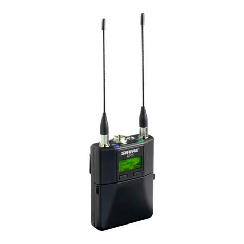
Shure UR5 User manual

Shure

Shure UR5 User manual

Shure PG2 User manual

Shure

Shure PG2 User manual

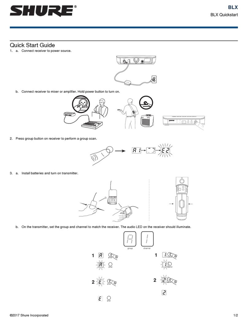
Shure BLX4R User manual

Shure

Shure BLX4R User manual

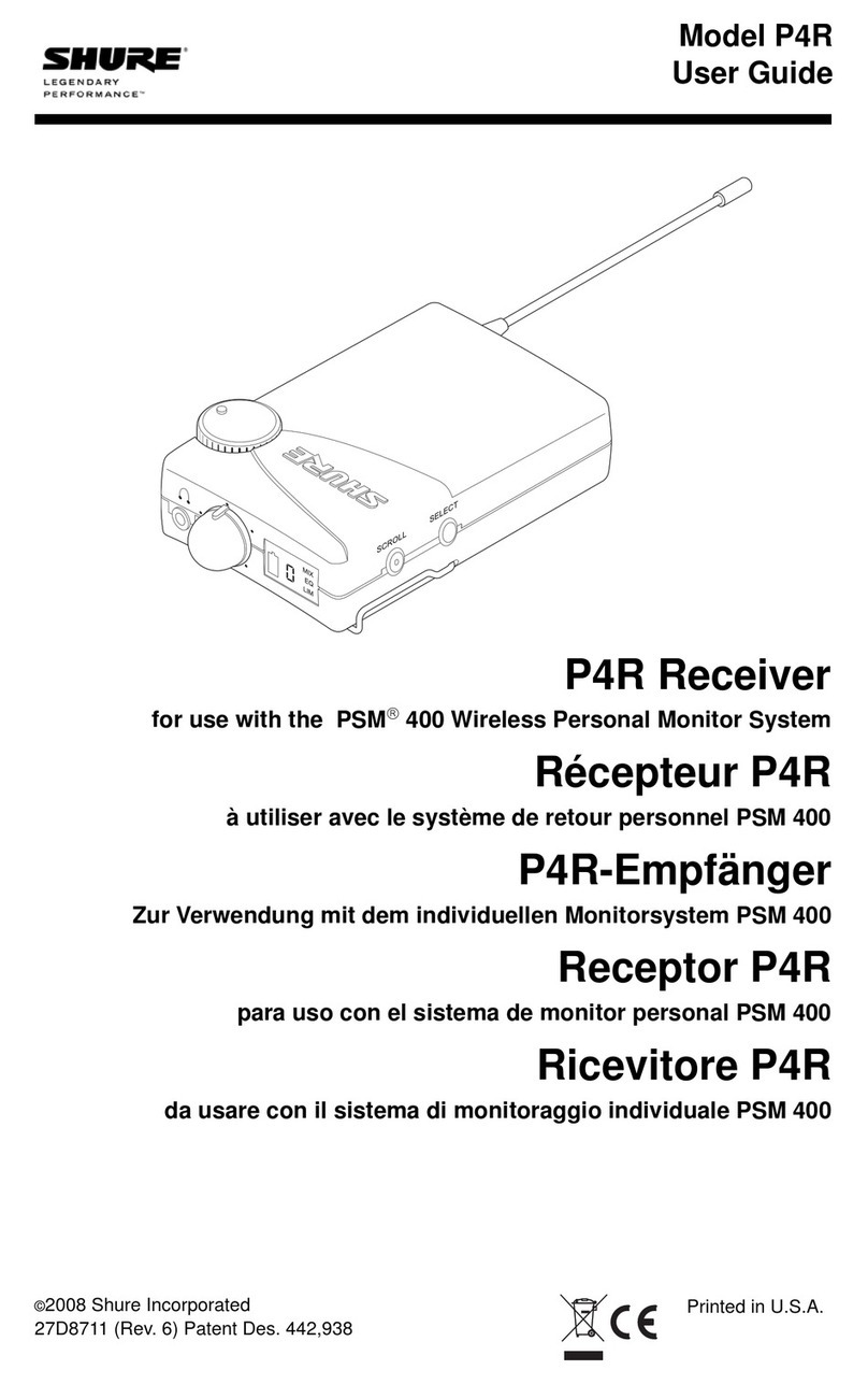
Shure P4R RECEIVER P4R User manual

Shure

Shure P4R RECEIVER P4R User manual

Shure GLXD6+ User manual

Shure

Shure GLXD6+ User manual

Shure SVX Wireless User manual

Shure

Shure SVX Wireless User manual

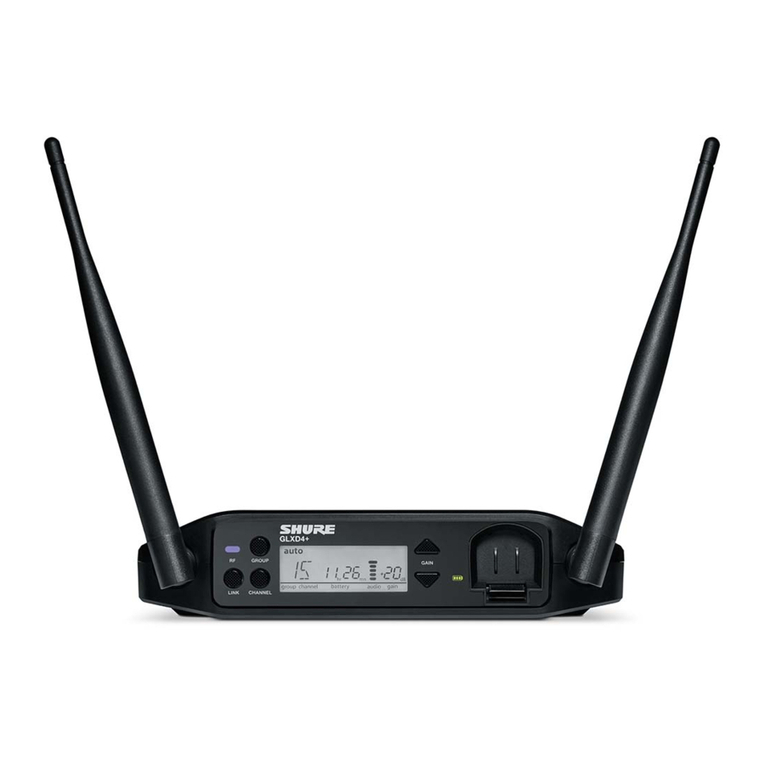
Shure GLXD4+ User manual

Shure

Shure GLXD4+ User manual

Shure GLXD4R+ User manual

Shure

Shure GLXD4R+ User manual

Shure GLXD6+ User manual

Shure

Shure GLXD6+ User manual

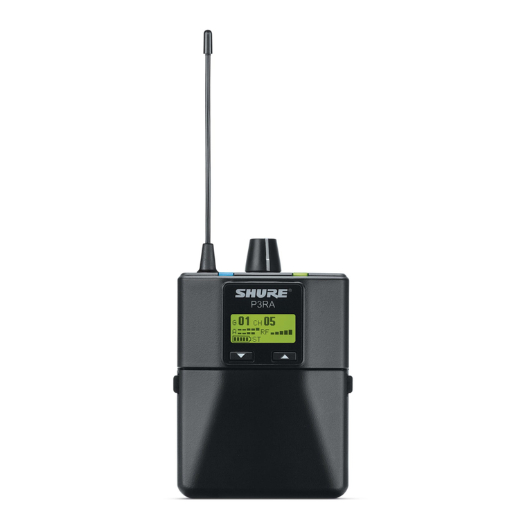
Shure P3RA User manual

Shure

Shure P3RA User manual

Shure GLX-D User manual

Shure

Shure GLX-D User manual

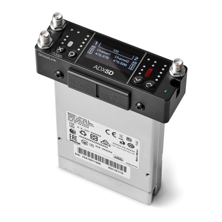
Shure ADX5D User manual

Shure

Shure ADX5D User manual

Shure GLXD4R User manual

Shure

Shure GLXD4R User manual

Shure U4S Operating instructions

Shure

Shure U4S Operating instructions

Shure GLXD16E User manual

Shure

Shure GLXD16E User manual

Shure LX4 User manual

Shure

Shure LX4 User manual

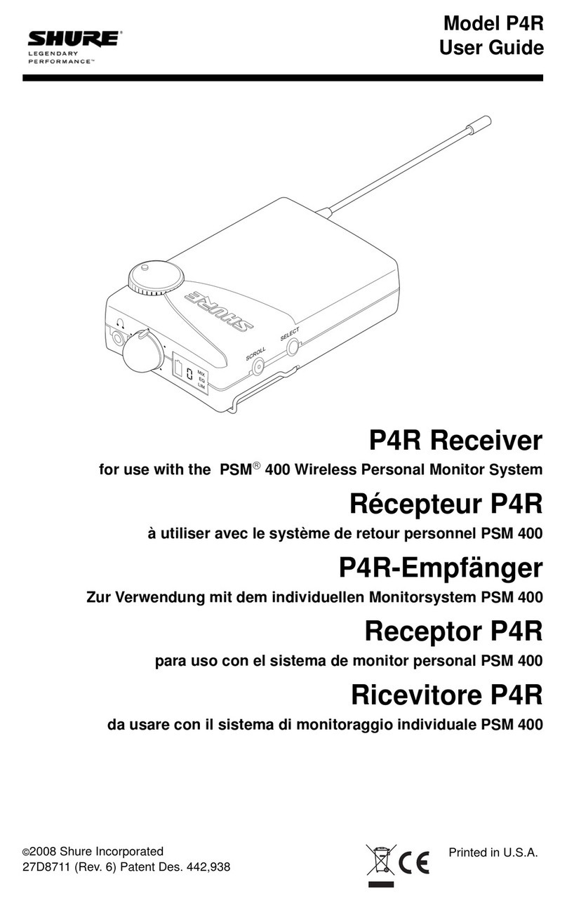
Shure P4R RECEIVER P4R User manual

Shure

Shure P4R RECEIVER P4R User manual

Shure GLXD24RE User manual

Shure

Shure GLXD24RE User manual

Shure SLX4L Owner's manual

Shure

Shure SLX4L Owner's manual

Shure GLXD4+ User manual

Shure

Shure GLXD4+ User manual

Shure AD4DUS-A User manual

Shure

Shure AD4DUS-A User manual

Shure T4 User manual

Shure

Shure T4 User manual

Popular Receiver manuals by other brands

Televes ZAS HD SAT user manual

Televes

Televes ZAS HD SAT user manual

Realistic DX-75 Operating and service instructions

Realistic

Realistic DX-75 Operating and service instructions

Saris 4620 Assembly instructions

Saris

Saris 4620 Assembly instructions

Mini DTR 206C PVR user manual

Mini

Mini DTR 206C PVR user manual

RF Elements TwistPort manual

RF Elements

RF Elements TwistPort manual

Denon DN-200WS user guide

Denon

Denon DN-200WS user guide

Yamaha RX-V467 owner's manual

Yamaha

Yamaha RX-V467 owner's manual

Russound SaphIR 858 instruction manual

Russound

Russound SaphIR 858 instruction manual

Quasonix RDMS Firmware update procedure

Quasonix

Quasonix RDMS Firmware update procedure

Pioneer XV-HTD1 Service manual

Pioneer

Pioneer XV-HTD1 Service manual

ATZ HDMI-V2-44HE150 manual

ATZ

ATZ HDMI-V2-44HE150 manual

Sony XNV-770BT MyTomTom Specifications

Sony

Sony XNV-770BT MyTomTom Specifications

Grundig STR 7122 TWIN Service manual

Grundig

Grundig STR 7122 TWIN Service manual

Creative Blaster Modem user guide

Creative

Creative Blaster Modem user guide

Panduit ATLONA AT-OME-RX11 installation guide

Panduit

Panduit ATLONA AT-OME-RX11 installation guide

VOLTCRAFT UTPS-40 operating instructions

VOLTCRAFT

VOLTCRAFT UTPS-40 operating instructions

JVC KW-ADV794 instructions

JVC

JVC KW-ADV794 instructions

Litelink VT-1001 operating instructions

Litelink

Litelink VT-1001 operating instructions

manuals.online logo
manuals.online logoBrands
  • About & Mission
  • Contact us
  • Privacy Policy
  • Terms and Conditions

Copyright 2025 Manuals.Online. All Rights Reserved.

Wireless Systems
SLX
Printed in U.S.A.
27A8903 (Rev. 3)
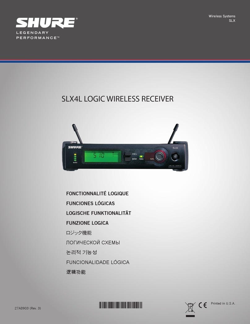
SLX4L LOGIC WIRELESS RECEIVER
FONCTIONNALITÉ LOGIQUE
FUNCIONEs LóGICAs
LOGIsChE FUNkTIONALITäT
FUNzIONE LOGICA
ロジック機能
логической схемы
논리적 기능성
Funcionalidade lógica
逻辑功能
©2012 Shure Incorporated
3
SLX4L User Guide Supplement:
Logic Functionality
SLX4L Receiver Overview
A logic circuit and associated terminal block connector is provided on the SLX4L receiver, in order to function optimally with
software echo cancellers and provide remote monitoring of transmitter battery life. Supported models are the MX690, MX890
transmitters.
Three logic pins on a terminal block connector are provided for Transmitter Mute Status, Transmitter Battery Status and Logic
Ground.
Operation
Two modes are provided: Normal and Logic:
Normal
In Normal mode, when the MX690, MX890, or any SLX transmitter mute button is pressed, audio is muted at the transmitter
and receiver output.
Logic
In Logic mode, when the MX690, MX890 mute button is pressed the transmitter still sends audio to the receiver, and the
receiver still sends an audio signal through the audio outputs. The transmitter Mute Status pin sends a TTL Logic High (+5V)
signal, telling the external device that the transmitter is in mute status.
Selecting Modes
The SLX4L ships in Normal mode. To switch between modes with the unit powered on, press and hold the Select button then
press the Power button. In Logic mode, the front panel LCD ashes
logic
. In Normal mode, the front panel will ash
nor
. An LED near the terminal block connector illuminates when Logic mode is active.
When an IR sync to the transmitter is performed, the receiver will set the transmitter to either Logic or Normal, whichever the
current state of the receiver is. Both transmitters and receivers will always remember the last mode status.
Compatible Models
Transmitters compatible with Logic mode are the MX690, MX890.
SLX4L Back Panel
4
LOGIC CONNECTION SPECIFICATIONS
The logic capability of the SLX4L receiver provides two functions: Transmitter Mute Status indication (which can be
used to signal and control other events) and Transmitter Battery status indication. The various logic functions and
their applications are presented in the following pin diagram and descriptions:
Pin 1: Transmitter Mute Status. In Logic mode, Pin 1 can be connected to a remote device and when transmitter
status is Active, logic level is Low (0V). When status is Muted, logic level is High (+5V). Typical applica-
tions include providing remote indication of transmitter status and activating external equipment (equalizer,
signal processor, loudspeakers, etc.) when used with a Room Control System (Crestron or AMX for example).
Transmitter Mute control mutes/unmutes an input channel on an automatic mixer. For connections, connect
the transmitter status pin to the podium mic mute input terminal on an automatic mixer. Connect the receiver
logic ground to the mixer logic ground.
NOTE: Whenever the receiver is in Normal mode, Pin 1 indicates transmitter on/off status. When the trans-
mitter is powered ON, logic output level is Low (0V.) When the transmitter is powered OFF, the logic
level is High (+5V)
Pin 2: Logic Ground. For connections, make all logic ground connections to this pin, including the power supply
ground of external logic circuitry. To avoid switching noise, do not connect logic ground to audio, chassis, or
rack grounds.
Pin 3: Transmitter Battery Status. Good Battery status sends a logic level of Low (0V). Low Battery status (1 hour
or less of battery life remaining) sends a logic level of High (+5V). Pin 3 can be used to control a remote
LED when battery is low. It can also be used to indicate low transmitter battery status on a remote control
panel when used with a Room Control System (Crestron or AMX for example).
www.shure.com ©2012 Shure Incorporated
Asia, Pacific:
Shure Asia Limited
22/F, 625 King’s Road
North Point, Island East
Hong Kong
Phone: 852-2893-4290
Fax: 852-2893-4055
Email: [email protected]
United States, Canada, Latin
America, Caribbean:
Shure Incorporated
5800 West Touhy Avenue
Niles, IL 60714-4608 USA
Phone: 847-600-2000
Fax: 847-600-1212 (USA)
Fax: 847-600-6446
Email: [email protected]
Europe, Middle East, Africa:
Shure Europe GmbH
Jakob-Dieffenbacher-Str. 12,
75031 Eppingen, Germany
Phone: 49-7262-92490
Fax: 49-7262-9249114
Email: [email protected]