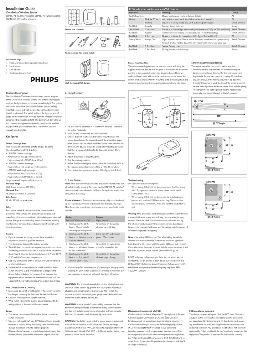
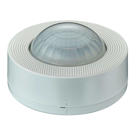
LRM2265 Instructions EN.PDF
Photocell (Ambient Light Override) adjustment:
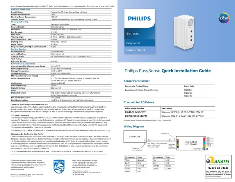
InordertousetheAmbientLightOverridefunctionalityofthesensor,thesensormust
bewiredtothepowerpack(OSPXX)usingtheGraywireinsteadoftheBluewire.This
featureallowstheusertoconserveenergybykeepingthecontrolledlightsoffwhennot
necessary.Thesensordoesthisbymeasuringtheamountofambientlightintheinstalled
areaandkeepingthecontrolledlightsoffifthereisenoughambientlightavailable.To
usethisfeature,thePhotocelladjustment(Blue)knobmustbeadjustedfromthedefault
position.Oncethisadjustmentismade,thecontrolledlightswillonlyturnoniftheambient
lightpresentislessthanthesetting.
To set the Photocell level (used with the Gray wire connection):
NOTE:Thissettingmustbeperformedwhenthenaturallightislowenoughtorequire
articiallight.
1. Removethecoverfromthesensor.
2. MakenoteofthepositionoftheRedandGreenknobs.RotatetheRedandGreen
knobsfullCCWandenterthesensor’sTestmodeasdescribedabove.
3.RotatetheBlueknobfullCCW.
4.WaitforthelightstoturnOFF.
5.RotatetheRedknobfullCW.
6.SlowlyrotatetheblueknobclockwiseuntilthelightsturnON.Thisisthecorrectsetting.
7.ReturntheRedandGreenknobstotheiroriginalposition.
8.Replacecover.Setting is complete.
Figure 2
Field-of-View Ranges
Wiring Diagram
Multiple Sensor, Single Power Pack
ADAPTIVE FUNCTIONS
Black (Hot)
Neutral (White)
Load
Blue
(Control)
Black
Red (24VDC)
Red
Blue
White
Black
White
Black
Red
Gray*
Blue
Blue
Blue Black
Black
Line
120/277/347VAC
60Hz
Sensor
LCA22xx Series
Power Pack
NC - Brown
NO - Brown/White
Common - Green
To HVAC
System
Gray*
TROUBLESHOOTING
• LightsdonotturnON
-Circuitbreakerorfusehastripped.
-Low-voltagemiswired.To Test:ConnectREDtoBLUEwireatpowerpacktoforce
lightsON.
-Linevoltagemiswired.To Test:ConnectBLUEtoBLUErelaywires(ofpowerpack)
toforcethelightsON.
• LightsstayON
-Constantmotion.To Test:ReduceREDknobby15%;removemotionsource.If
unsatisfactory,movesensor.
-Infraredsensorcan"see"intohallway.To Test:Putsensorintimertestmodewalk
andwalkhallway.IflightscontinuetocomeON,movesensor.
• LightturnsONtoolong
-Timersettingtoohigh.To Test:Checkswitchsettings.Typicalsettingis10minutes.
PRODUCT INFORMATION
• Fortechnicalassistance,contactusat1-800-372-3331
• Visitourwebsiteatwww.philips.com
* NOTE:WhenusingthePhotocellfunction,connecttheGraywireofthesensorto
theBluewireofthepowerpack.DO NOTusetheBluewireofsensor.
NOTE:Ensuretocapwirethatisnotbeingused.
TABLE 3: WIRE DESIGNATIONS
Name Color Gauge Temp/Voltage
200°C/600V
200°C/600V
200°C/600V
200°C/600V24
24
24
24
Red
Black
Blue
Gray
Power(+24V)
DCReturn
Occupancy
Occupancy/Photocell
TheSensorcontinuallyanalyzestheparametersofthemotiondetectionsignaland
adjustsitsinternaloperationtomaximizedetectionofmotionwhileminimizingthe
effectsofnoise(electricalnoise,aircurrents,temperaturechanges,etc…).
Operation:
Whenthelightsturnon,thesensorinitiallyentersthe"walk-through"mode.Oncethe
roomisoccupiedforlongerthan2.5minutes,thesensorexitsthe"walk-through"mode
andentersthe"Occupied"mode.Whenthesensorisrstinstalled,thedelayed-offtime
fortheoccupiedmodeisbasedontheTimeadjustmentsettings.Whilethesensoris
inuse,thedelayed-offtimewillchange,basedonhowthesensoradaptstotheroom
conditions.Wheneverthesensorsubsequentlyturnson,thevalueofthedelayed-offtime
willbetheadaptedvalue(refer to Occupancy Pattern Learning For Delayed-Off Time).
TheadaptedsettingscanberesetusingtheDIPswitch.
Occupancy Pattern Learning For Delayed-Off Time:
Thesensorwillautomaticallychangethedelayed-offtimeinresponsetothe
occupancyandenvironmentalconditionsofthespaceitisinstalledin.Thesensor
analyzesthemotionsignalpropertiesandwillminimizethedelayed-offtimeduration
whenthereisfrequentmotiondetection,andlengthenthedelayed-offtimeduration
whenthereisweakandinfrequentmotiondetection.
Inthecaseofafalse-offcondition(lightsturnoffwhentheroomisoccupied),the
delayed-offtimedurationwillimmediatelybelengthenedtopreventfurtherfalseturnoffs.
Occupancy Pattern Learning for UltrasonicTechnology:
Thesensorlearnstheoccupancypatternsofaspaceduringthecourseofaday,fora
sevendayperiod.Atanygiventime,thesensorwilllookatthecollecteddataandadjust
itsultrasonicsensitivity.Thesensorwilladjustthesensitivitytomakeitlesslikelyto
turnonduringaperiodofnon-occupancyandmorelikelytoturnonduringaperiodof
occupancy.ThisadaptingfeatureisnotapplicablewhenthesensorisinPIRonlymode.
Default Settings:
Adjustmentknobsettingsasper“FactoryDefaultSetting”,(refer to Table 1 and
Figure 1).
AllswitchesintheOFFposition,exceptA4,whichisintheONposition(refer toTable 2).
TABLE 1 : AJUSTMENT KNOB SETTINGS
Knob
Color Function Knob SettingSymbol Factory Default
Setting
Red
Green
Sets the infrared
range
Sets the ultrasonic
range
Range Setting
Full CCW = min. (OFF)
Full CW = max.
Range Setting
Full CCW = min. (OFF)
Full CW = max.
75 %
75 %
Black Delayed - Off Time Full CCW = min. (30 sec.)
Full CW = max. (30 min.)
50 %
(10 min)
Blue Ambient Light Override
(Gray wire only)
Full CCW - Lights stay OFF
Full CW - Lights always turn ON
(NO ambient light override)
Range - 100-3000 LUX
100 %
Mounting Location Diagram
58 ft
31 ft
16 ft
11.5 ft
31 ft
58 ft
8 ft SIDE VIEW
TOP VIEW
Minor motion, Ultrasonic
Major motion, Ultrasonic
68 ft
Minor motion, IR
Major motion, IR
3 ft 8 ft 15 ft
23 ft 32 ft
0
0
11.5 ft
16 ft
*NOTE: ThissettingisonlyusediftheSingleTechnologyOption(switchA1)isselected.
Switch
A1
A2*
A3
A4
B1
B2
B3
B4
TABLE 2: SWITCH SETTINGS
Switch Settings
Bank A
Bank B
Switch Functions
Single/Multi-Tech Mode
PIR/Ultrasonic Mode
Manual Mode
Walk-Through Disable
Override to ON
Override to OFF
Test Mode
LEDs Disable
ON
ON
Single Tech
Ultrasonic
Auto Adapting Disabled
Walk-Through Disabled
Lights Forced ON
Lights Forced OFF
LEDs Disabled
OFF
OFF
Multi-Tech
PIR
Auto Adapting Enabled
Walk-Through Enabled
Auto Mode
Auto Mode
LEDs Enabled
OFF ON OFF = Enter/Exit Test Mode
Test Mode: Tosetthedelayed-offtimeto6secondsforperformingawalktest.While
thesensorisintestmode,theLED’swillashamberonceasecond.
1. ENSURE POWER IS ON.
2. Removefrontcover.
3. LocateDipSwitch3inBankB(B3)(refer to Figure 1).B3willbeintheOFFposition
fromthefactory.
4. ToenterTestMode,moveswitchtoONandbacktoOFF.Thetestmodehasnow
beenenteredwitha6secondtime-out.NOTE:IfB3isalreadyintheONposition,
thentestmodecanbeenteredbyjustmovingittotheOFFposition.
NOTES:
1.
Thetimerwillremaininthe6secondtestmodefor15minutes,thenautomaticallyexit
testmodeandresettothedelayed-offtimesettingasdenedbytheblacktimerknob.
2. Tomanuallytakethetimeroutofthe6secondtestmode,simplytoggletheswitchB3
fromOFFtoONandbacktoOFF.
B
ON
1
A
ON
1
B
ON
1
A
ON
1
DIP Switches
B3
Minimum Setting
Adjust Knob Rotation Direction
Factory Default Setting
Delayed-Off Time Selection (Black Knob)
Figure 1
Minimum and Default Settings
MINMA
