manuals.online logo
Brands
  1. Home
  2. •
  3. Brands
  4. •
  5. Philips
  6. •
  7. Switch
  8. •
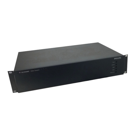
  9. Philips PM2120 User manual

Philips PM2120 User manual

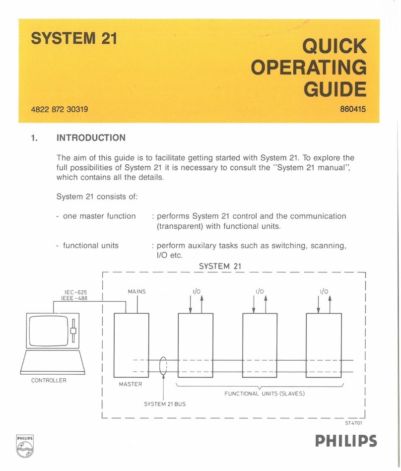
SYSTEM
21
UNIVERSAL SWITCH
4822 872 30324
1. GENERAL
PM2120
851120
The PM2120 programmable Universal Switch provides the following features.
20 individual ON/OFF switches with one common contact per pair.
-
10
change over switches, make-before-break or break-before-make mode.
2. TECHNICAL DATA
Cross talk isolation
Series resistance
Isolation resistance
Open contact
Frequency range
Max. switching voltage
Max. switching current
Max. switching power (Resistive load)
Max. common mode voltage between
any two terminals and between any
terminal and the System
21
bus
Supply voltage
Supply current
User 1/0 terminal
Relay SIYilching time
Time from matching the execution
condition to all relays settled
Settling time after power
on
Make-before-break switching time
Break-before-make switching time
>60dB
(DC to
1OOkHz,
R0 =
500)
<0.5Q
>1o9o
>1o9o
DC
to
100kHz
30Vrms (DC to
1OOkHz)
200mArms (DC
to
100kHz)
10VA
(DC
or peak
AC)
30Vrms or 42Vdc
7,5-16Vdc (powered out of the master module)
Typ. 125mA; Max. 225mA
Type
F161
female, 37 contacts
dimensions according to MIL-C-24308
<10ms
<25
ms
<50ms
<20ms
<20ms
PHILIPS
3. ADDRESS SETTING
ADDRESS
20
Example : Selected address
is
203
4. PROGRAMMING
In
this chapter the three possible modes with the related information
is
given.
For the general slave commands, see the System
21
manual.
Mode 0 : 20 individual ON/OFF switches with one common contact per pair.
(default mode)
Syntax : (MO,]Cn,On
MO
Cn
On
Mode selection (optional)
Close channel n
Open channel n
Functional diagram
6 4 2
n=0
.
..
19or
n=n1-n2
where
O
~
n1
~
n2
~
19
eg.
CB-12
means close switch 8 up to and
including
12
.
Note: Default all switches are open.
(Also after reset command
Rt)
0 J channel number
-rear plug
J channel number
Mode
1:
10
change-over switches, make before break.
Mode
2:
10 change-over switches, break before make.
Syntax: [Mm,] An, Bn
Mm
An
Bn
mode selection (optional)
channel n in position A
channel n in position B
Functional diagram
5
8 A
ror
4
8 A
ror
3
8 A
-or
2
8 A
r"f>
1
8 A
-or
m=1
or 2
n=0
..
..
..9
n = n1-n2 where
O~n1
~n2~9
e.g. AS-9 means put switch 5 up to and
including 9 in the A position.
Note: default all switches
in
position A.
(also after reset command
R1)
0 - channel
number
8 A
ror-
~
0 v
9
18
17 16
15
14
13
12
11
10
9 8 7 6 5 4 3 2 1
37 36 35
34
33
32
31
30
29 28 27 26 25
24
23
22
21
20
0 0 0 0 0 0
-rear
plug
-o\>-
B A
9
L-o\>-
B A
8
-o\,..
B A
7
-o
\,.
B A
6 -channel
number
5. GENERAL SLAVE FUNCTIONS
Commands Synchronization
modes
Code
E?
D?
I?
M?
Pn,
Description
Send execution mode
Send
dump
data
Send identification of module
Send operating mode
<funct. cmd>Store functional commands on
(n
= 0.
...
19) block-memory position n
R? Send ready-line control mode
RO
Reset
as
after power on
R1
Reset
as
after mode change
R2 Clear block/scan memory
S?
Send status
T n
(n
= 0,
1)
Functional test n
X Execute
luB[,n]
Initiate block-operation up to
(n
= 0 .
..
.
19)
and including block-memory
position n
In
(n
= 0 ....19) Initiate block position n
IuS Initiate one scan
Code
EuT
EuU
EuX
Description
Execute on trigger
Execute unconditional
Execute on X
RuD
Ready-line control disable
RuE
Ready-line control enable
Scan
function:
Mode 0: switches are sequentially closed.
Mode 1 and 2: switches sequentially change
from A to
B.
In
all modes, one switch at a time.
" u" means space character.
For full details of these commands,
see System
21
Manual.
6. DISPLAY
ON
PM
2190
MODE
IN
OUT
Display shows mode information
Operating mode; example: Mode 0
LSynchronization data '); example: ready-line control enable
~xecute
.!:!n£onditional
Displays shows switch settings mode 0
First switch
of display
sequence
open closed closed open
.--Position
First switch of 7
display sequence A 6 5
A B
1) See System
21
Manual
MODE
IN
OUT
Display shows switch settings mode 1; mode
2.
4 - Switch number
A-
Position

Other Philips Switch manuals

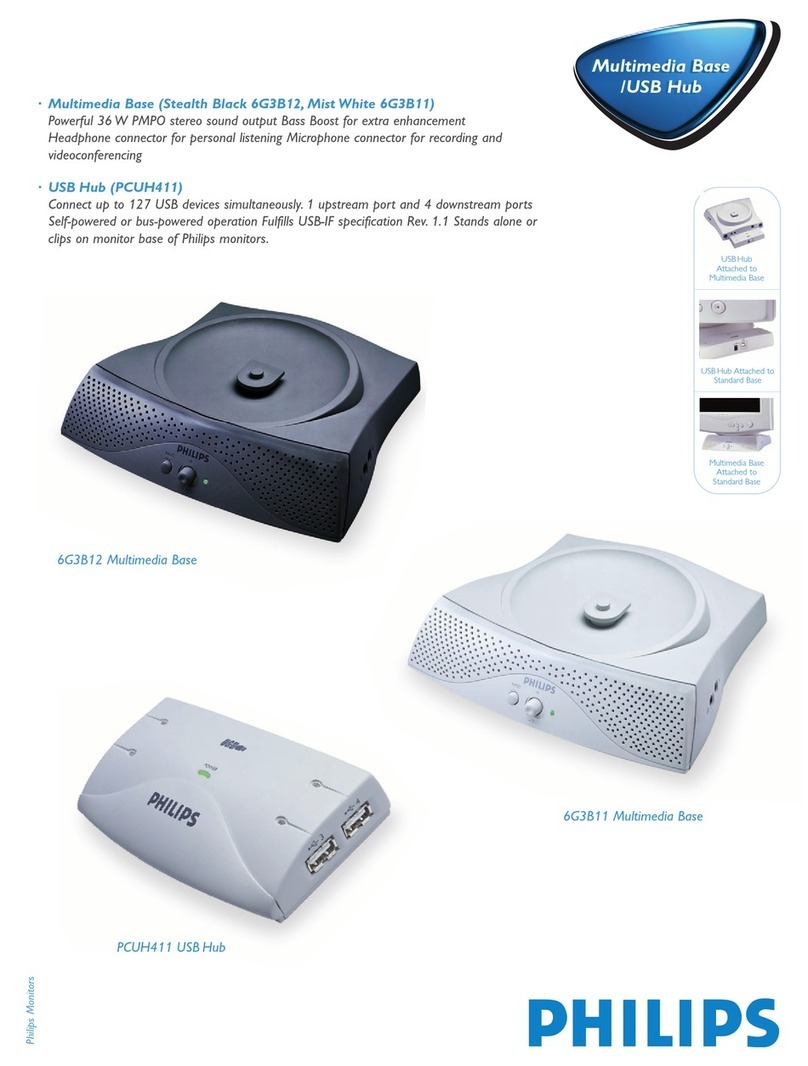
Philips Multimedia Base 6G3B12 User manual

Philips

Philips Multimedia Base 6G3B12 User manual

Philips Integrated Circuits PDIUSBH12 User manual

Philips

Philips Integrated Circuits PDIUSBH12 User manual

Philips SWS3685S/10 User manual

Philips

Philips SWS3685S/10 User manual

Philips SWS3435H/37 User manual

Philips

Philips SWS3435H/37 User manual

Philips US2-PH61153 User manual

Philips

Philips US2-PH61153 User manual

Philips SDW5058 User manual

Philips

Philips SDW5058 User manual

Philips LightMaster P1PE-KNX-2P User manual

Philips

Philips LightMaster P1PE-KNX-2P User manual

Philips SWV2054 User manual

Philips

Philips SWV2054 User manual

Philips PCUH411R User manual

Philips

Philips PCUH411R User manual

Philips US2-PH61148 User manual

Philips

Philips US2-PH61148 User manual

Philips SWV3052 User manual

Philips

Philips SWV3052 User manual

Philips SWS2463H User manual

Philips

Philips SWS2463H User manual

Philips PIP3210-R Owner's manual

Philips

Philips PIP3210-R Owner's manual

Philips Sonicare 300 SerieS User manual

Philips

Philips Sonicare 300 SerieS User manual

Philips SWS2326W/27 User manual

Philips

Philips SWS2326W/27 User manual

Philips 2net Gen 2 User manual

Philips

Philips 2net Gen 2 User manual

Philips SDW5034 User manual

Philips

Philips SDW5034 User manual

Philips SWS2822T User manual

Philips

Philips SWS2822T User manual
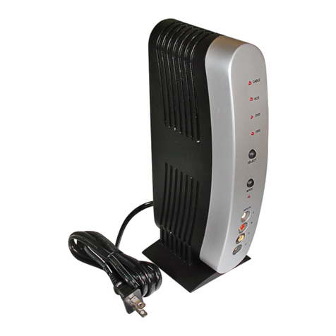
Philips SWV9173GR/37 User manual

Philips

Philips SWV9173GR/37 User manual

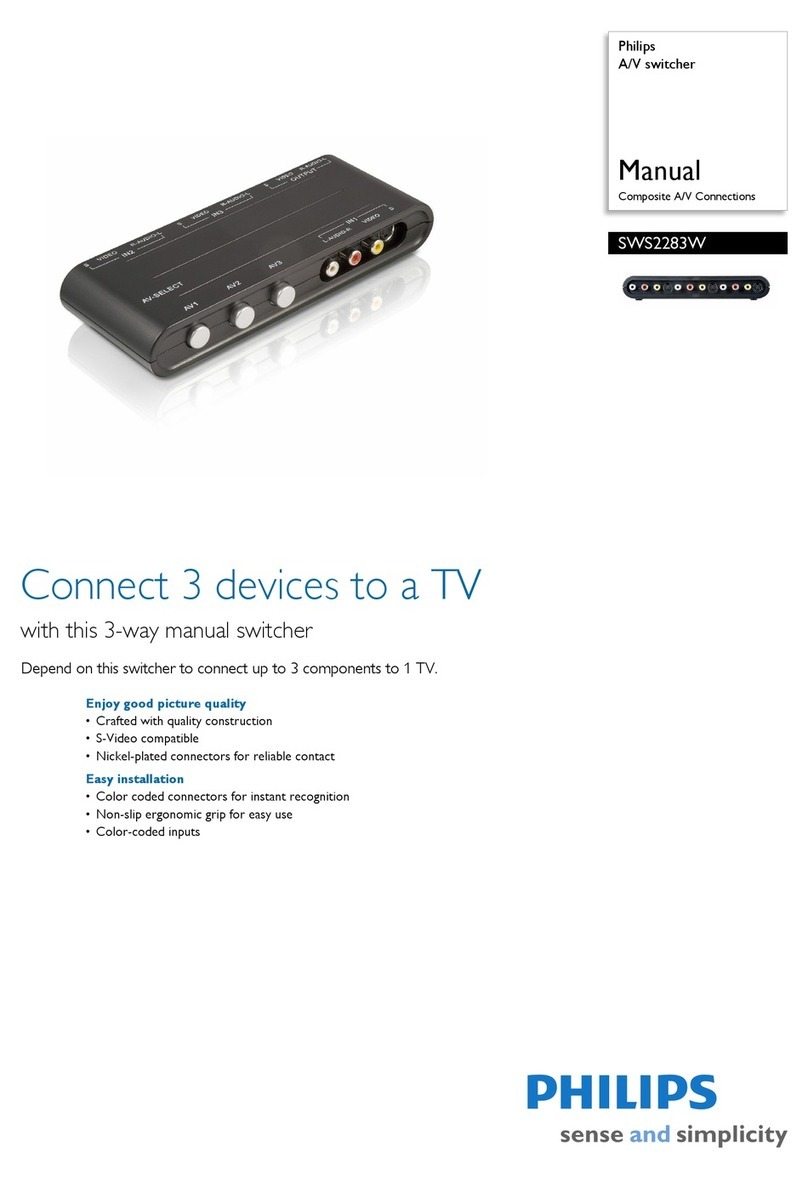
Philips SWS4683S/10 User manual

Philips

Philips SWS4683S/10 User manual

Philips SWV3053 User manual

Philips

Philips SWV3053 User manual
Philips hue User manual

Philips

Philips hue User manual

Philips LDH 2545/00 User manual

Philips

Philips LDH 2545/00 User manual

Philips SWV6813 User manual

Philips

Philips SWV6813 User manual

Popular Switch manuals by other brands

Enable-IT 8202 Technical reference guide

Enable-IT

Enable-IT 8202 Technical reference guide

LevelOne FEP-0840 Quick guide / user manual

LevelOne

LevelOne FEP-0840 Quick guide / user manual

D-Link DES-1024D Quick installation guide

D-Link

D-Link DES-1024D Quick installation guide

Niles Infrared Sensor Expansion Hub IRH610 Installation & operation guide

Niles

Niles Infrared Sensor Expansion Hub IRH610 Installation & operation guide

Cisco Catalyst 3560-X-24T Hardware installation guide

Cisco

Cisco Catalyst 3560-X-24T Hardware installation guide

TRENDnet TPE-TG80G datasheet

TRENDnet

TRENDnet TPE-TG80G datasheet

Yamamoto Electric Works Co., Ltd. MS65F instruction manual

Yamamoto Electric Works Co., Ltd.

Yamamoto Electric Works Co., Ltd. MS65F instruction manual

Supermicro SSE-G48-TG4 Quick configuration guide

Supermicro

Supermicro SSE-G48-TG4 Quick configuration guide

Altronix HubSat4Di installation guide

Altronix

Altronix HubSat4Di installation guide

Allied Telesis AT-GS950/8POE datasheet

Allied Telesis

Allied Telesis AT-GS950/8POE datasheet

Cisco 4506 - Catalyst Switch supplementary guide

Cisco

Cisco 4506 - Catalyst Switch supplementary guide

Edimax GS-5424PLC V2 Quick installation guide

Edimax

Edimax GS-5424PLC V2 Quick installation guide

ATEN CS1768 manual&nbsp;

ATEN

ATEN CS1768 manual&nbsp;

Ruijie RG-NIS3100 Series Hardware  installation and reference guide

Ruijie

Ruijie RG-NIS3100 Series Hardware installation and reference guide

Exar XRP2523 manual

Exar

Exar XRP2523 manual

Vetra Systems USB-804-KM User instructions

Vetra Systems

Vetra Systems USB-804-KM User instructions

Plantronics Electronic Hook Switch manual

Plantronics

Plantronics Electronic Hook Switch manual

Extron electronics DTP T DSW 4K 333 Setup guide

Extron electronics

Extron electronics DTP T DSW 4K 333 Setup guide

manuals.online logo
manuals.online logoBrands
  • About & Mission
  • Contact us
  • Privacy Policy
  • Terms and Conditions

Copyright 2025 Manuals.Online. All Rights Reserved.