Phoenix Contact FL LCX CABLE 5 E Guide

User manual
Assembling and mounting a leaky cable and
the accessories

2020-06-24
PHOENIX CONTACT GmbH & Co. KG • Flachsmarktstraße 8 • 32825 Blomberg • Germany
phoenixcontact.com
107048_en_02
Assembling and mounting a leaky cable and the accessories
Designation Order No.
FL LCX CABLE 5 E 2702860
FL LCX CABLE 24 E 2702553
FL LCX CON-N-F E 2702518
FL LCX TOOL E 2702519
FL LCX CLAMP E 2702520
FL LCX 50 OHM RSMA 2702702
FL LCX PIG-EF142-N-N 2700677
User manual
This user manual is valid for:
UM EN FL LEAKY CABLE, Revision 02

Table of contents
107048_en_02 PHOENIX CONTACT 3 / 32
Table of contents
1 For your safety ...........................................................................................................................5
1.1 Labeling of warning notes...................................................................................... 5
1.2 Qualification of users ............................................................................................. 5
1.3 Product changes ................................................................................................... 5
2 Assembling and mounting a leaky cable and the accessories ...................................................7
2.1 Description ............................................................................................................ 7
2.2 Structures .............................................................................................................. 7
2.2.1 Parameterization .................................................................................... 7
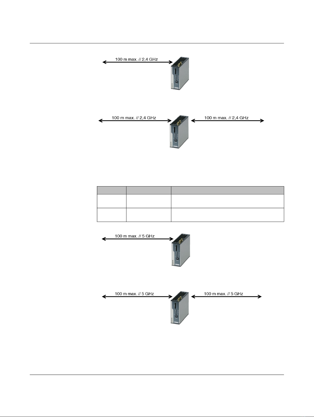
2.2.2 Connecting a leaky cable to a WLAN access point .............................. 10
2.2.3 Splitting the leaky cable using two ports .............................................. 11
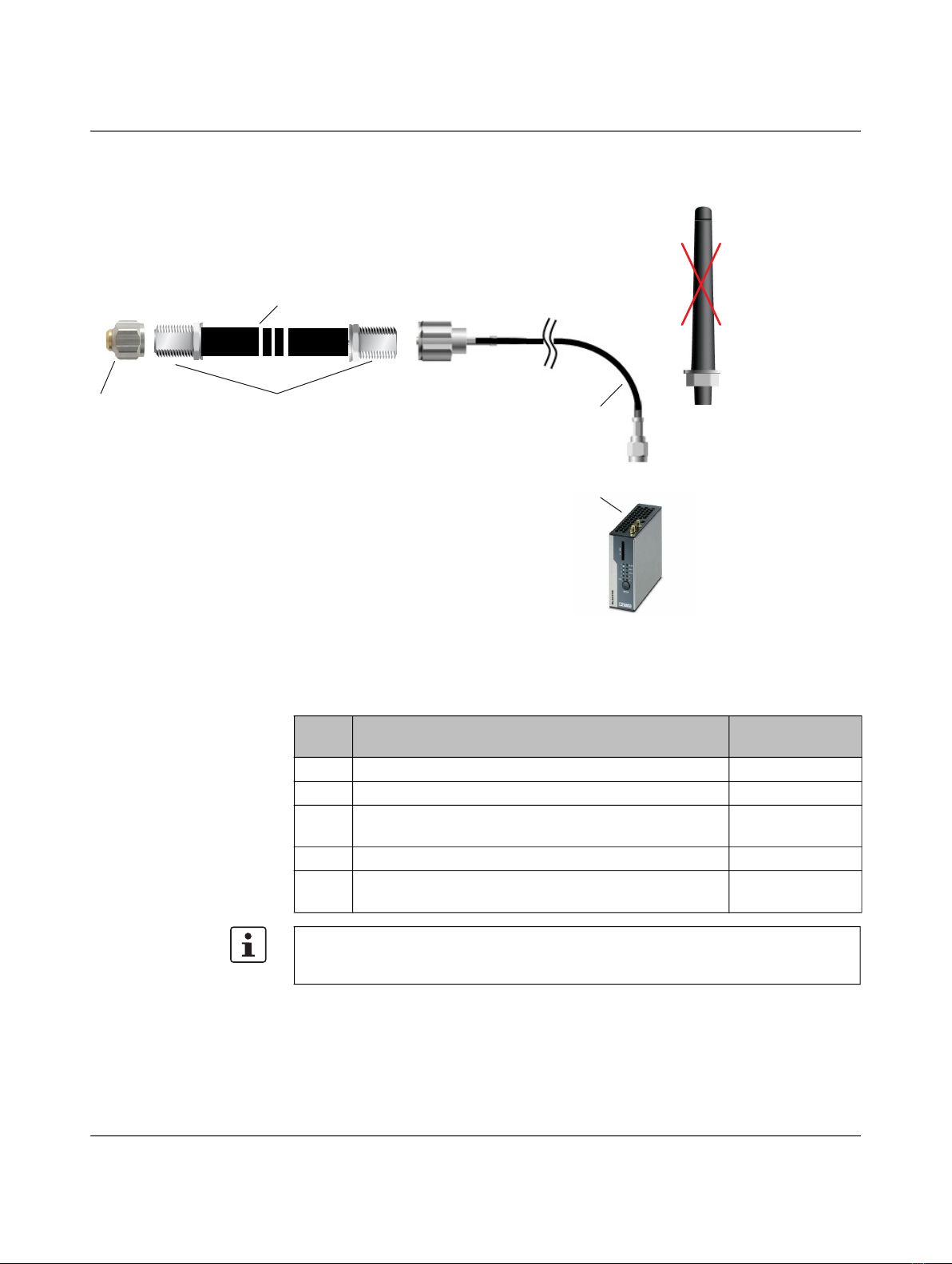
2.2.4 Connecting two sections using a pigtail ............................................... 12
2.2.5 Connecting two sections using a pigtail (part two) ............................... 13
2.2.6 Transition at an EHB switch ................................................................. 14
2.2.7 Transition at an EHB switch with antenna ............................................ 15
2.2.8 Installing a termination resistor on the access point/client .................... 16
2.3 WLAN clients on a leaky cable ............................................................................ 17
2.3.1 Mobile device: FL WLAN 110x with integrated special antennas (2.4 &
5 GHz) ................................................................................................. 17
2.3.2 Mobile device: FL WLAN 511x client with external antenna ................. 18
2.4 Roaming on a leaky cable ................................................................................... 19
2.4.1 Roaming using the FL WLAN 1100 client ............................................. 19
2.4.2 Roaming using the FL WLAN 511x client ............................................. 20
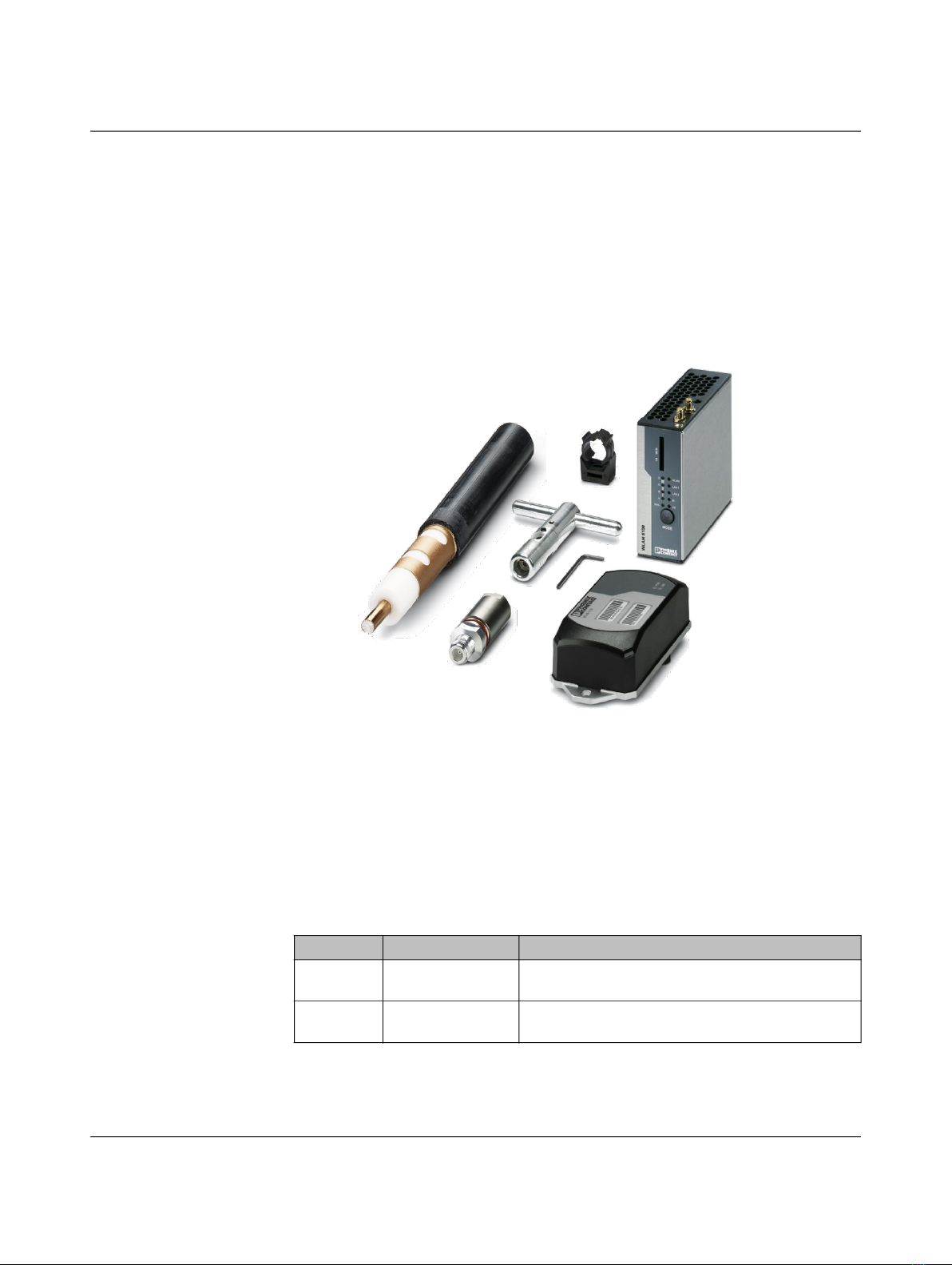
2.5 Assembling the leaky cable ................................................................................. 21
2.5.1 Leaky cable and installation of accessories ......................................... 21
2.5.2 Connecting the N connector to the leaky cable .................................... 22
2.5.3 Mounting clamp for mechanical installation of the cable ...................... 23
2.5.4 Installation on the panel or DIN rail ....................................................... 23
2.5.5 Special case: installation on the floor ................................................... 24
2.5.6 Distance between antenna and leaky cable ......................................... 24
3 Technical data .........................................................................................................................25
A Appendixes...............................................................................................................................27
A 1 List of figures ....................................................................................................... 27
A 2 List of tables ........................................................................................................ 29

For your safety
107048_en_02 PHOENIX CONTACT 5 / 32
1 For your safety
Read this user manual carefully and keep it for future reference.
1.1 Labeling of warning notes
1.2 Qualification of users
electrical machines. The persons must be able to recognize dangers.
1.3 Product changes
Changes or modifications to hardware and software of the device are not permitted.
Incorrect operation or modifications to the device can endanger your safety or damage the
device. Do not repair the device yourself. If the device is defective, please contact
Phoenix Contact.
This symbol indicates hazards that could lead to personal injury.
There are three signal words indicating the severity of a potential injury.
DANGER
Indicates a hazard with a high risk level. If this hazardous situation is not
avoided, it will result in death or serious injury.
WARNING
Indicates a hazard with a medium risk level. If this hazardous situation is not
avoided, it could result in death or serious injury.
CAUTION
Indicates a hazard with a low risk level. If this hazardous situation is not avoided,
it could result in minor or moderate injury.
This symbol together with the NOTE signal word alerts the reader to a situation
which may cause damage or malfunction to the device, hardware/software, or
surrounding property.
Here you will find additional information or detailed sources of information.

Assembling and mounting a leaky cable and the accessories
107048_en_02 PHOENIX CONTACT 7
2 Assembling and mounting a leaky cable and the
accessories
2.1 Description
This document describes the configuration options for a leaky cable and the required
accessories.
Figure 2-1 Accessories for a leaky cable
2.2 Structures
2.2.1 Parameterization
Leaky cable lengths
Table 2-1 FL LCX CABLE 24 E leaky cable lengths // 2702553
Frequency Maximum length Comments
2.4 GHz 100 m Connecting a WLAN AP see “Connecting a leaky
cable to a WLAN access point” on page 10
2.4 GHz 2 x 100 m Using two antenna ports of the FL WLAN 511x
(configure X5, X7)

FL LEAKY CABLE
8PHOENIX CONTACT 107048_en_02
Figure 2-2 The maximum length of a leaky cable on a WLAN AP is 100 m (2.4 GHz).
Figure 2-3 The length of a leaky cable using two ports of the WLAN AP is 200 m,
maximum (2.4 GHz).
Figure 2-4 The maximum length of a leaky cable on a WLAN AP is 100 m (5 GHz).
Figure 2-5 The length of a leaky cable using two ports of the WLAN AP is 200 m,
maximum (5 GHz).
Table 2-2 FL LCX CABLE 5 E leaky cable lengths // 2702860
Frequency Maximum length Comments
5 GHz 100 m Connecting a WLAN AP see “Connecting a leaky
cable to a WLAN access point” on page 10
5 GHz 2 x 100 m Using two antenna ports of the FL WLAN 511x
(configure X5, X7)

Assembling and mounting a leaky cable and the accessories
107048_en_02 PHOENIX CONTACT 9
Number of possible WLAN devices (clients) connected to one WLAN access point
The number of connected devices depends on the quality of encryption. Due to the higher
data rate when using a higher encryption quality, the number of devices connected at the
same time is reduced.
Table 2-3 Quality of encryption
Encryption Number of clients
WPA-PSK (TKIP) 32
WPA2-PSK (AES) 64
Please note that the cycle time of the transmission protocol, e.g., PN or Eth/IP (depending
on the application), may reduce the number of devices.
Table 2-4 Different WLAN access points
Description Designation Order
No.
WLAN access point, client, WLAN 802.11 a, b, g, n,
frequency 2.4 GHz, 5 GHz, IP20, connections:
COMBICON for 10 ... 36 V DC, 2 x RJ45 for LAN, central
cluster management, WBM, 802.11i: WPA2, WPA-PSK,
TKIP, AES, connections for 2 antennas (MIMO
technology)
FL WLAN 5110 1043193
WLAN access point for USA/Canada (FCC/IC), client,
WLAN 802.11 a, b, g, n, frequency 2.4 GHz, 5 GHz,
IP20, connections: COMBICON for 10 ... 36 V DC,
2 x RJ45 for LAN, central cluster management, WBM,
MIMO technology, 802.11i: WPA2, WPA-PSK, TKIP,
AES
FL WLAN 5111 1043201

FL LEAKY CABLE
10 PHOENIX CONTACT 107048_en_02
2.2.2 Connecting a leaky cable to a WLAN access point
Figure 2-6 Connecting a leaky cable
No antennas shall be
mounted on the device
12 4
3
5
Table 2-5 Key
Positi
on
Designation Order No.
1 Termination resistor // FL LCX 50-OHM 2884978
2 Connector // FL LCX CON-N-F E 2702518
3 Leaky cable // FL LCX CABLE 24 E
Leaky cable // FL LCX CABLE 5 E
2702553
2702860
4 Pigtail // RAD-PIG-RSMA/N-1 2903264
5 WLAN access point // FL WLAN 5110
WLAN access point // FL WLAN 5111
1043193
1043201
Please note that we recommend terminating unused antenna ports on WLAN access
points with a resistor in leaky cable applications. You can use the product
FL LCX 50 OHM RSMA with the order number 2702702 for this purpose.

Assembling and mounting a leaky cable and the accessories
107048_en_02 PHOENIX CONTACT 11
2.2.3 Splitting the leaky cable using two ports
Figure 2-7 Connecting two leaky cables
12 4
3
12 4
3
5
Table 2-6 Key
Positi
on
Designation Order No.
1 Termination resistor // FL LCX 50-OHM 2884978
2 Connector // FL LCX CON-N-F E 2702518
3 Leaky cable // FL LCX CABLE 24 E
Leaky cable // FL LCX CABLE 5 E
2702553
2702860
4 Pigtail // RAD-PIG-RSMA/N-1 2903264
5 WLAN access point // FL WLAN 5110
WLAN access point // FL WLAN 5111
1043193
1043201
Please note that we recommend terminating unused antenna ports on WLAN access
points with a resistor in leaky cable applications. You can use the product
FL LCX 50 OHM RSMA with the order number 2702702 for this purpose.

FL LEAKY CABLE
12 PHOENIX CONTACT 107048_en_02
2.2.4 Connecting two sections using a pigtail
Figure 2-8 Connecting two sections using a pigtail
Table 2-7 Key
Positi
on
Designation Order No.
1 Termination resistor // FL LCX 50-OHM 2884978
2 Connector // FL LCX CON-N-F E 2702518
3 Leaky cable // FL LCX CABLE 24 E
Leaky cable // FL LCX CABLE 5 E
2702553
2702860
4 Antenna cable // FL LCX PIG-EF142-N-N 2700677
5 Pigtail // RAD-PIG-RSMA/N-1 2903264
6 WLAN access point // FL WLAN 5110
WLAN access point // FL WLAN 5111
1043193
1043201
Please note that we recommend terminating unused antenna ports on WLAN access
points with a resistor in leaky cable applications. You can use the product
FL LCX 50 OHM RSMA with the order number 2702702 for this purpose.

Assembling and mounting a leaky cable and the accessories
107048_en_02 PHOENIX CONTACT 13
2.2.5 Connecting two sections using a pigtail (part two)
Figure 2-9 Connecting two sections using a pigtail (part two)
It is also possible to connect two leaky cables via a standard coaxial cable with low power
loss. Flexible pigtails can be used for short distances.
5
2 3 2
6
2 3 21 4
Table 2-8 Key
Positi
on
Designation Order No.
1 Termination resistor // FL LCX 50-OHM 2884978
2 Connector // FL LCX CON-N-F E 2702518
3 Leaky cable // FL LCX CABLE 24 E
Leaky cable // FL LCX CABLE 5 E
2702553
2702860
4 Connecting cable with N connectors (0.5 m) //
FL LCX PIG-EF142-N-N
2700677
5 Pigtail // RAD-PIG-RSMA/N-1 2903264
6 WLAN access point // FL WLAN 5110
WLAN access point // FL WLAN 5111
1043193
1043201
Please note that we recommend terminating unused antenna ports on WLAN access
points with a resistor in leaky cable applications. You can use the product
FL LCX 50 OHM RSMA with the order number 2702702 for this purpose.

FL LEAKY CABLE
14 PHOENIX CONTACT 107048_en_02
2.2.6 Transition at an EHB switch
Figure 2-10 Transition at an EHB switch
21 3 421 3 421 3 4
11
1
2
3
5 2 1
Table 2-9 Key
Positi
on
Designation Order No.
1 Leaky cable // FL LCX CABLE 24 E
Leaky cable // FL LCX CABLE 5 E
2702553
2702860
2 Connector // FL LCX CON-N-F E 2702518
3 Adapter // RAD-ADP-N/M-SMA/F 2917036
5 Termination resistor // FL LCX 50-OHM 2884978
4 Connecting cable with N connectors (3 m) //
RAD-CAB-EF142-3M
2884512

Assembling and mounting a leaky cable and the accessories
107048_en_02 PHOENIX CONTACT 15
2.2.7 Transition at an EHB switch with antenna
An antenna may be used for better coverage of larger switching areas. Please note that this
will lead to a significant increase in the covered area.
Figure 2-11 Transition at an EHB switch with antenna
21 3 421 3 421 3 4
11
1
2
3
3 2 15
Table 2-10 Key
Position Designation Order No.
1 Leaky cable // FL LCX CABLE 24 E
Leaky cable // FL LCX CABLE 5 E
2702553
2702860
2 Connector // FL LCX CON-N-F E 2702518
3 Adapter // RAD-ADP-N/M-SMA/F 2917036
5 Termination resistor // FL LCX 50-OHM 2884978
4 Connecting cable with N connectors (3 m) //
RAD-CAB-EF142-3M
2884512
5 Antenna // RAD-ISM-2400-ANT-OMNI-5-0 2884923

FL LEAKY CABLE
16 PHOENIX CONTACT 107048_en_02
2.2.8 Installing a termination resistor on the access point/client
Figure 2-12 Installing a termination resistor on the access point/client
Table 2-11 Key
Positi
on
Designation Order No.
1 Termination resistor // FL LCX 50 OHM RSMA 2702702
2 Connector RSMA
3 WLAN access point/client // FL WLAN 5110
WLAN access point/client // FL WLAN 5111
1043193
1043201

Assembling and mounting a leaky cable and the accessories
107048_en_02 PHOENIX CONTACT 17
2.3 WLAN clients on a leaky cable
2.3.1 Mobile device: FL WLAN 110x with integrated special
antennas (2.4 & 5 GHz)
Figure 2-13 FL WLAN 110x
The WLAN Ethernet client (FL WLAN 110x) is suitable for the wireless connection of
moving devices to the leaky cable. The integrated circular polarized antenna is well
designed for the wireless field of the leaky cable. For information about roaming, see
“Roaming on a leaky cable” on page 19.
Table 2-12 Device versions
Designation Order No.
FL WLAN 1100 2702534
FL WLAN 1101 2702538

FL LEAKY CABLE
18 PHOENIX CONTACT 107048_en_02
2.3.2 Mobile device: FL WLAN 511x client with external antenna
Figure 2-14 FL WLAN 511x client with external antenna
Combined with an antenna, the FL WLAN 511x may also be used as a powerful client on a
vehicle. The antenna couples the WLAN signal to the leaky cable.
Table 2-13 Key
Positi
on
Designation Order No.
1 Antenna // ANT-DIR-2459-01 2701186
2 Pigtail // various lengths
RAD-PIG-RSMA/N-0.5 (0.5 m length)
RAD-PIG-RSMA/N-1 (1 m length)
RAD-PIG-RSMA/N-2 (2 m length)
RAD-PIG-RSMA/N-3 (3 m length)
2903263
2903264
2903265
2903266
3 WLAN access point // FL WLAN 5110
WLAN access point // FL WLAN 5111
1043193
1043201
2
1
3
Please note that we recommend terminating unused antenna ports in WLAN clients with
a resistor in leaky cable applications. You can use the product FL LCX 50 OHM RSMA
with the order number 2702702 for this purpose.

Assembling and mounting a leaky cable and the accessories
107048_en_02 PHOENIX CONTACT 19
2.4 Roaming on a leaky cable
2.4.1 Roaming using the FL WLAN 1100 client
Roaming
Systems covering large areas require several leaky cable sections. These connect to
different WLAN access points within a network. The transition of the WLAN client (e.g., an
electric monorail system) from one leaky cable section to another requires a roaming
process from one access point to the neighboring access point. Roaming processes are
initiated by the WLAN client.
Figure 2-15 Leaky cable for track-guided vehicles // FL WLAN 110x as a client
Schematic view of the roaming process from one WLAN AP to the next by means of a
command from the PLC to the FL WLAN 1100.
If you want to use the FL WLAN 110x on the leaky cable, we recommend initializing the
roaming process via a command from the controller (Switched Roaming). In this case, a
command for switching to the next WLAN access point is initialized from the controller
connected to the client. This process is based on the position of the transition from one
section of the leaky cable to another (position encoders such as bar codes, etc.).
Table 2-14 Alternative devices
Designation Order No.
FL WLAN 1100 2702534
FL WLAN 1101 2702538

FL LEAKY CABLE
20 PHOENIX CONTACT 107048_en_02
2.4.2 Roaming using the FL WLAN 511x client
When the FL WLAN 511x is used as the client, roaming can be done on the basis of the
signal strength (RSSI). In these cases, we recommend using the leaky cable section layout
shown in the figure. This leads to the necessary difference between the signal levels.
Figure 2-16 Roaming based on different signal strengths
This manual suits for next models
13
Table of contents
Other Phoenix Contact Cables And Connectors manuals