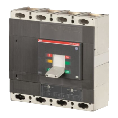
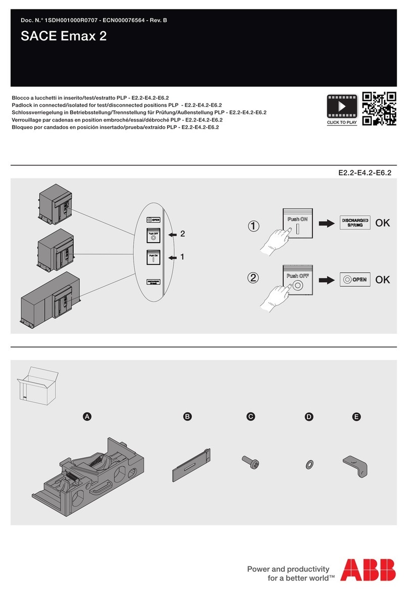
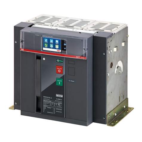
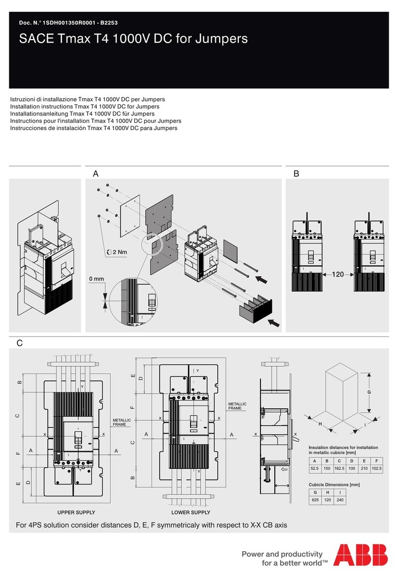
ABB EMAX E2.2 Series Service manual


STATO DI FUNZIONAMENTO RAPPRESENTATO
Lo schema è rappresentato nelle seguenti condizioni:
- interruttore aperto e inserito
-circuiti in assenza di tensione
-sganciatori non intervenuti
-
molle di chiusura scariche
LEGENDA
* =
A1 =
A3 =
Vedere la nota indicata dalla lettera
Applicazioni ubicate sulla parte mobile dell'interruttore
Applicazioni ubicate sulla parte fissa dell'interruttore: nuovo
EKIP CARTRIDGE
A3M Applicazioni ubicate sulla parte fissa del vecchio interruttore GE M-
PACT, GE M-PACT Plus o GEC ALSTHOM M-PACT, Legrand DMX,
Legrand DPX,
BTicino Megabreak, F.T.M.C. Power-WAVE Plus
A4 = Apparecchi e collegamenti indicativi per comando e segnalazione,
esterni all'interruttore
BUS1 = Interfaccia seriale con il bus esterno
BUS2 =Interfaccia seriale ridondante con il bus esterno
LINK BUS = Interfaccia con il Link bus esterno
D = Ritardatore elettronico della bobina di minima tensione YU, esterno
all'interruttore
GZi(DBi) = Ingresso selettività di zona per protezione G oppure ingresso in
direzione “inversa” per protezione D
GZo(DBo) = Uscita selettività di zona per protezione G oppure uscita in direzione
“inversa” per protezione D
I01…32 = Ingressi digitali programmabili
I 41…43 51…53 = Ingressi analogici da sensore di temperatura
I 44-54 =Ingressi analogici da sensore 4-20mA
K51 Sganciatore elettronico di protezione di massima corrente tipo EKIP DIP,
EKIP TOUCH, EKIP HI-TOUCH, EKIP G TOUCH, EKIP G HI-TOUCH
K51/COM = Modulo comunicazione
K51/MEAS = Modulo misure
K51/SIGN = Modulo di segnalazione
K51/SUPPLY = Modulo alimentazione ausiliaria (110-240VAC/DC e 24-48VDC)
K51/SYNC = Modulo sincronizzazione
K51/TEMP = Modulo di controllo temperatura
K51/YC =Comando di chiusura da sganciatore di protezione EKIP
K51/YO =Comando di apertura da sganciatore di protezione EKIP
M = Motore per la carica delle molle di chiusura
O 01...32 = Contatti di segnalazione programmabili
O SC = Contatto per il controllo di sincronismo
Q = Interruttore
Q/1
...
10= Contatti ausiliari aperto/chiuso dell'interruttore
Q/26-27 = Contatti ausiliari aperto/chiuso usati all'interno dello sganciatore di
RC protezione
Sensore di protezione RC (corrente residua)
RTC EKIP = Contatto ausiliario pronto a chiudere, usato all'interno dello
sganciatore di protezione
RTC = Contatto ausiliario pronto a chiudere
S33M/1-2 = Contatti di fine corsa del motore carica molle
S43 = Commutatore di predisposizione al comando distanza / locale
S51-S51/2 = Contatti di segnalazione di trip
S75/1…6 = Contatti per la segnalazione di posizione interruttore in posizione di
estratto, test e inserito
SC = Pulsante o contatto per la chiusura dell'interruttore
SO = Pulsante o contatto per l'apertura immediata dell'interruttore
SO1 = Pulsante o contatto per l'apertura dell'interruttore con intervento
ritardato
SR = Pulsante o contatto per il reset elettrico del contatto di trip S51
SZi(DFi) = Ingresso selettività di zona per protezione S oppure ingresso in
direzione “diretta” per protezione D
SZo(DFo) = Uscita selettività di zona per protezione S oppure uscita in direzione
“diretta” per protezione D
TI/L1-L2-L3 = Trasformatore di corrente fase L1-L2-L3
TI/N = Trasformatore di corrente sul neutro
TU1-2 = Trasformatore di tensione di isolamento (esterno all'interruttore)
Uaux = Tensione di alimentazione ausiliaria
UI/L1-L2-L3 = Sensore di corrente fase L1-L2-L3
UI/N = Sensore di corrente sul neutro
UI/O =Sensore di corrente omopolare
W2 = Interfaccia seriale con il bus interno (bus locale)
W9…14 =Connettore RJ45 per unità di interfaccia e per moduli comunicazione
W9R…12R = Connettore RJ45 per moduli comunicazione ridondanti
XConnettore di consegna per i circuiti ausiliari del nuovo
interruttore EMAX E2.2-E4.2
XB1…XB7 = Connettori per le applicazioni dell'interruttore
XCT2 =Morsettiera del nuovo EKIP CARTRIDGE
XK1…XK3 = Connettori per i circuiti ausiliari dello sganciatore di protezione EKIP
XK7 = Connettore per i circuiti ausiliari dei moduli di comunicazione
XX = Connettore di consegna per i circuiti ausiliari del vecchio interruttore
XXF
GE M-PACT, GE M-PACT Plus o GEC ALSTHOM M-PACT, Legrand
DMX,Legrand DPX,
BTicino Megabreak, F.T.M.C. Power-WAVE Plus
Morsettiera di consegna per i contatti di posizione del vecchio
interruttore GE M-PACT, GE M-PACT Plus o GEC ALSTHOM M-PACT,
Legrand DMX, Legrand DPX,
BTicino Megabreak, F.T.M.C. Power-WAVE
Plus
YC =Bobina di chiusura
YC2 =Seconda bobina di chiusura
YO =Bobina di apertura
YO1 = Bobina di apertura per massima corrente
YO2 =Seconda bobina di apertura
YR = Bobina per il reset elettrico del contatto di trip S51
YU = Bobina di minima tensione
=
=
=
=
=

NOTE
A. Lo schema rappresenta i collegamenti da realizzare per l'adattamento di un
interruttore in esecuzione estraibile serie EMAX E2.2-E4.2 al connettore
dell'interruttore serie GE M-PACT, GE M-PACT Plus o GEC ALSTHOM M-PACT,
Legrand DMX, Legrand DPX,
BTicino Megabreak, F.T.M.C. Power-WAVE Plus
a cui
va a sostituirsi.
Per i circuiti del nuovo interruttore EMAX E2.2-E4.2 vedere lo schema
1SDM000091R0001.
Per i circuiti del vecchio interruttore serie GE M-PACT, GE M-PACT Plus o GEC
ALSTHOM M-PACT, Legrand DMX, Legrand DPX,
BTicino Megabreak, F.T.M.C.
Power-WAVE Plus
vedere il relativo catalogo.
C. La protezione differenziale del vecchio interruttore GE M-PACT, GE M-PACT Plus o
GEC ALSTHOM M-PACT, Legrand DMX, Legrand DPX,
BTicino Megabreak, F.T.M.C.
Power-WAVE Plus
può essere sostituita da quella del nuovo interruttore EMAX 2
con l'utilizzo del sensore di corrente omopolare UI/O sul collegamento verso terra.
D. Per interruttori tripolari: la bobina di Rogowski sul neutro esterno del vecchio
interruttore GE M-PACT, GE M-PACT Plus o GEC ALSTHOM M-PACT, Legrand DMX,
Legrand DPX,
BTicino Megabreak, F.T.M.C. Power-WAVE Plus
può essere sostituita
dal sensore di corrente UI/N del nuovo interruttore EMAX 2.
E. Con la soluzione DR Direct Replacement massimo 6 contatti ausiliari disponibili (3
nc + 3 na).
F. In presenza di più moduli Ekip Com, il contatto S75/5 va collegato una volta sola
su un solo modulo. In caso non siano presenti i contatti di posizione sulla parte
fissa del vecchio interruttore GE M-PACT, GE M-PACT Plus o GEC ALSTHOM
M-PACT, Legrand DMX, Legrand DPX,
BTicino Megabreak, F.T.M.C. Power-WAVE
Plus
ponticellare i morsetti 1-4.
G. In presenza dell'accessorio Ekip Cartridge di Fig. 32, possono essere incluse nella
fornitura solo fino a tre applicazioni tra le Fig. 41…58 prese una sola volta.
Il modulo Ekip Com selezionato può essere duplicato, se necessario, scegliendo tra
le Fig. 61…67.
H. Cablare i cavi A17 e A19 (PAMM) in W1 (Ekip Com Modbus) e i cavi A18 e A20
(PAMM) in W2 (Ekip Com Modbus) per passaggio da comunicazione Modbus a 4 fili
a comunicazione Modbus a 2 fili.

OPERATING STATE SHOWN
The diagram illustrates the components in the following conditions:
- circuit-breaker open and racked-in
circuits de-energized
releases not tripped
closing springs discharged
KEY
* = See note indicated by the letter
A1 = Applications located on the mobile part of the circuit-breaker
A3 = Applications located on the fixed part of the circuit-breaker: new
EKIP CARTRIDGE
A3M =Applications located on the fixed part of old GE M-PACT, GE M-PACT
Plus o GEC ALSTHOM M-PACT
, Legrand DMX, Legrand DPX, BTicino
Megabreak, F.T.M.C. Power-WAVE Plus
circuit-breaker
A4 = Indicative switchgear and connections for operation and signaling,
outside circuit-breaker
BUS1 = Serial interface with external bus
BUS2 =Redundant serial interface with external bus
LINK BUS = Interface with external Link bus
D = Electronic time-delay device for undervoltage release coil YU,
outside circuit-breaker
GZi(DBi) = Zone selectivity input for G protection or input in “reverse” direction
for D protection
GZo(DBo) = Zone selectivity output for G protection or output in “reverse”
direction for D protection
I 01…02 = Programmable digital inputs
I 41…43 51…53 = Analog inputs from temperature sensor
I 44-54 =Analog inputs from 4-20mA sensor
K51 Electronic overcurrent protection trip unit of the types: EKIP DIP, EKIP
TOUCH, EKIP HI-TOUCH, EKIP G TOUCH, EKIP G HI-TOUCH
K51/COM = Communication module
K51/MEAS = Measurement module
K51/SIGN = Signaling module
K51/SUPPLY = Auxiliary supply module (110-240VAC/DC and 24-48VDC)
K51/SYNC = Synchronizing module
K51/TEMP = Temperature monitoring module
K51/YC =Closing control from the EKIP protection trip unit
K51/YO =Opening control from the EKIP protection trip unit
M = Motor for closing springs charging
O 01...32 = Programmable signaling contacts
O SC = Synchronism monitoring contact
Q = Circuit-breaker
Q/1 10 = Auxiliary open/closed contacts of the circuit-breaker
Q/26-27 = Auxiliary open/closed contacts used internally by the trip unit
RC = RC (residual current) protection sensor
RTC EKIP = Auxiliary ready to close contact of circuit-breaker, used internally by
the trip unit
RTC = Contact for signalling circuit-breaker is ready to close
S33M/1-2 = Limit contacts of spring loading motor
S43 = Switch for presetting remote / local control
S51-S51/2 = Trip signalling contacts
S75/1…6 = Contacts for signaling circuit-breaker in racked-out, test and
racked-in position
SC = Pushbutton or contact for closing the circuit-breaker
SO =Pushbutton or contact for immediate opening circuit-breaker
SO1 = Pushbutton or contact for opening circuit-breaker with time-delayed
trip
SR = Pushbutton or contact for electrical resetting of S51 trip contact
SZi(DFi) = Zone selectivity input for S protection or input in “direct” direction
for D protection
SZo(DFo) = Zone selectivity output for S protection or output in “direct” direction
for D protection
TI/L1-L2-L3 = L1-L2-L3 phase current transformer
TI/N = Current transformer on neutral conductor
TU1-2 = Insulation voltage transformer (outside circuit-breaker)
Uaux = Auxiliary supply voltage
UI/L1-L2-L3 = L1-L2-L3 phase current sensor
UI/N = Current sensor on neutral conductor
UI/O = Homopolar current sensor
W2 =Serial interface with internal bus (local bus)
W9…14 =Connector RJ45 for interface unit and for communication modules
W9R…12R = Connector RJ45 for redundant communication modules
XDelivery connector for auxiliary circuits for new EMAXE2.2-E4.2
circuit-breaker
XB1…XB7 = Connectors for circuit-breaker applications
XCT2 = New EKIP CARTRIDGE terminal board
XK1…XK3 = Connectors for auxiliary circuits of the EKIP protection trip unit
XK7 =Connector for auxiliary circuits of communication modules
XX =Delivery connector for auxiliary circuits for old GE M-PACT, GE
M-PACT Plus o GEC ALSTHOM M-PACT,
,Legrand DMX, Legrand DPX,
BTicino Megabreak, F.T.M.C. Power-WAVE Plus
circuit-breaker
XXF =Delivery terminal board for position for old GE M-PACT, GE M-PACT
Plus o GEC ALSTHOM M-PACT,
, Legrand DMX, Legrand DPX, BTicino
Megabreak, F.T.M.C. Power-WAVE Plus
circuit-breaker
YC = Closing coil
YC2 = Second closing coil
YO = Opening coil
YO1 = Coil for opening due to overcurrent
YO2 =Second opening coil
YR = Coil for electrical resetting of trip contact S51
YU = Undervoltage coil
=
=

NOTES
A. The diagram indicates the connections for adaptation of EMAX E2.2-E4.2 series
circuit-breaker to GE M-PACT, GE M-PACT Plus, GEC ALSTHOM M-PACT,
Legrand
DMX, Legrand DPX, BTicino Megabreak, F.T.M.C. Power-WAVE Plus
series
withdrawable version circuit-breaker connectors in place of which it has to located.
For circuit of new EMAX E2.2-E4.2 series circuit-breaker see diagram
1SDM000091R0001.
For circuit of old GE M-PACT, GE M-PACT Plus, GEC ALSTHOM M-PACT
, Legrand
DMX, Legrand DPX, BTicino Megabreak, F.T.M.C. Power-WAVE Plus
series
circuit-breaker see corresponding catalogue.
C. Differential protection of old GE M-PACT, GE M-PACT Plus, GEC ALSTHOM M-PACT
,
Legrand DMX, Legrand DPX, BTicino Megabreak, F.T.M.C. Power-WAVE Plus
series circuit-breaker can be replaced by new EMAX 2 circuit breaker protection
with the use of UI/O homopolar current sensor on earth connection point.
D. For three poles circuit breaker: Rogowski coil on external neutral conductor of old
GE M-PACT, GE M-PACT Plus, GEC ALSTHOM M-PACT
, Legrand DMX, Legrand DPX,
BTicino Megabreak, F.T.M.C. Power-WAVE Plus
series circuit-breaker can be
replaced by UI/N current sensor of new EMAX 2 circuit breaker.
E. With DR Direct Replacement solution maximum 6 auxiliary contacts available (3 nc
+ 3 no).
F. In the presence of several Ekip Com modules, S75/5 contact should be connected
only once to a single module. If there are no carriage position contacts on the fixed
part of the old GE M-PACT, GE M-PACT Plus, GEC ALSTHOM M-PACT
, Legrand DMX,
LegrandDPX, BTicino Megabreak, F.T.M.C. Power-WAVE Plus
series circuit
breaker, the terminals 1-4 should be short-circuited.
G. In the presence of Ekip Cartridge accessory in Fig. 32, up to three applications
between Fig. 41…58 taken only once can be supplied.
The Ekip Com module selected can be duplicated, if required, by choosing between
Fig. 61…67.
H. Connect A17-A19 (PAMM) cables to W1 (Ekip Com Modbus) and A18-A20 (PAMM)
cables to W2 (Ekip Com Modbus) for switching from 4-wire Modbus communication
to 2-wire Modbus communication.
This manual suits for next models
1
Other ABB Circuit Breaker manuals

ABB
ABB SACE Emax 2 User manual

ABB
ABB eVD4 Quick guide

ABB
ABB K-Line Plus KP-8 Installation and operating instructions

ABB
ABB Emax 2 Retrofill AKR-30-800A Product manual

ABB
ABB DB BREAKER User manual

ABB
ABB GE Power Break II User manual
ABB
ABB VBF Series Guide

ABB
ABB SACE Emax 2 User manual

ABB
ABB H569-445 User manual

ABB
ABB Tmax RC221 User manual
Popular Circuit Breaker manuals by other brands

GE
GE AKR-75 Series INSTRUCTIONS - INSTALLATION AND OPERATION

Stahl
Stahl 8562/5 operating instructions

ComAp
ComAp InteliMains NT IM-NT-BB reference guide

Siemens
Siemens GER Instructions, Installation, Operation, Maintenance

GE
GE M-PACT Operating and installation instructions

Eaton
Eaton DHP VR + Series Instruction book