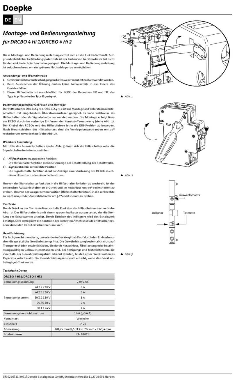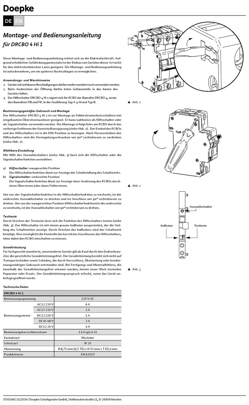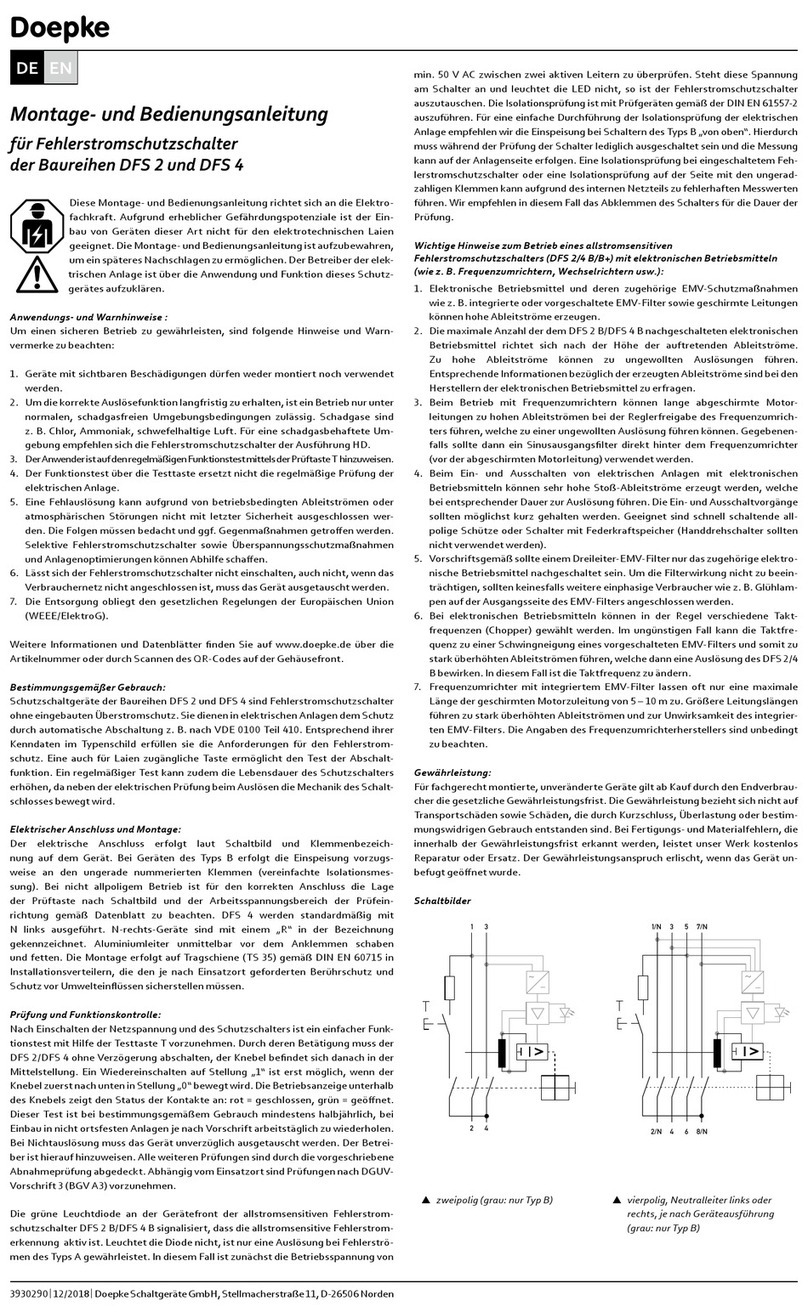
Technical data
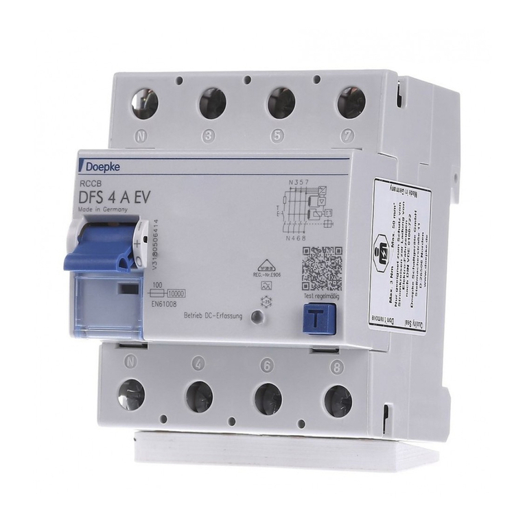
DFS 4 A EV
Series
Number of poles
Tripping characteristics
Rated current
of test circuit
Active
additional
device
in sys. on
DC tripping
current
times (DC)
voltage
(DC detection)
Internal con
sumption
Rated surge voltage capacity
Max. rated switching
capacity
Surge current strength
Rated insulation voltage
Rated frequency
Current heat loss per current
path
fuse
gG
Max. number of conductors
Connector
section
solid
stranded
Tightening torque
Installation position optional
Max. operating altitude
Mech. endurance
Electr. endurance
Storage temperature
Ambient
temperature
Standard
Resistance to climatic
changes
Shock resistance
>>
Mounting
distribution installation housing
Thermoplast
Protection class
Sealable Yes
Dimensions
Installation depth
Design requirements
Eective value of tripping threshold
Pulsating
Additional device
Additional device
Warranty
All professionally installed, unaltered devices are covered by warranty during the
statutory guarantee period from the day of purchase by the end user. The warranty
overloading or improper use. In the event of defects in workmanship or material,
which are discovered within the warranty period, the company will provide repair or
replacement free of charge. The warranty will be rendered null and void if the device
is opened without authorisation.
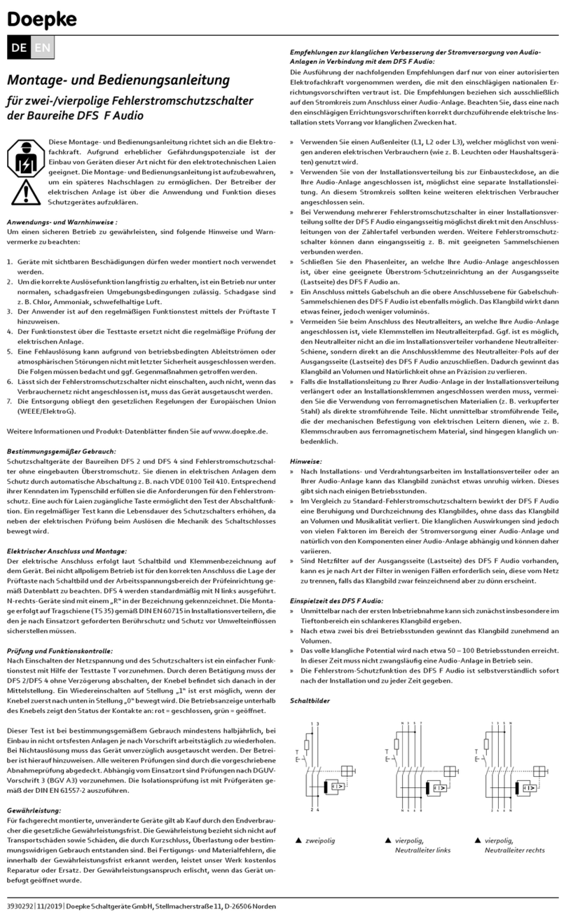
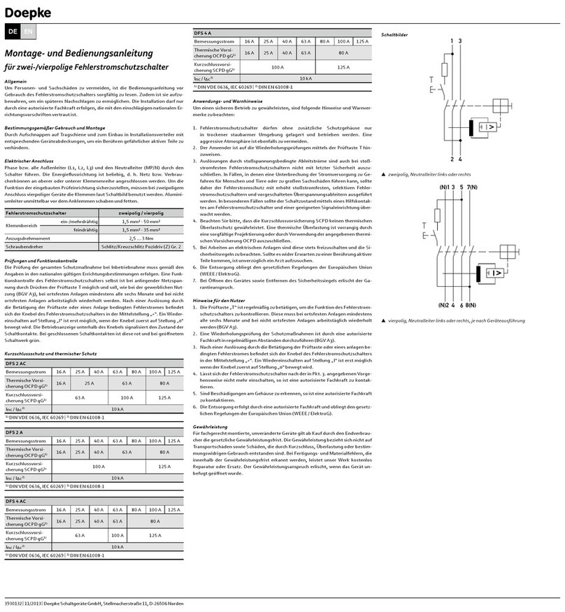
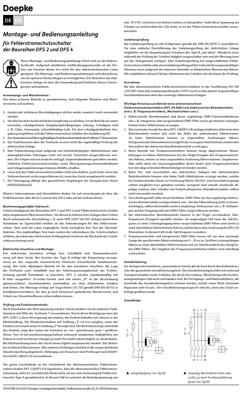
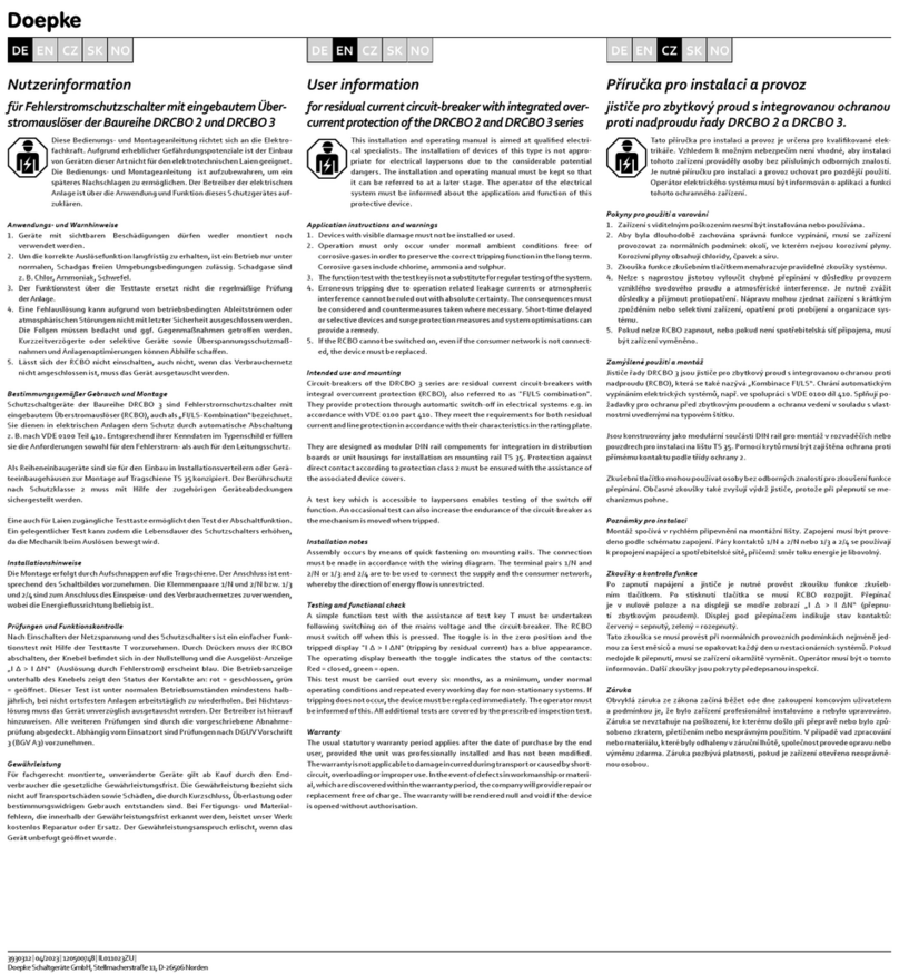
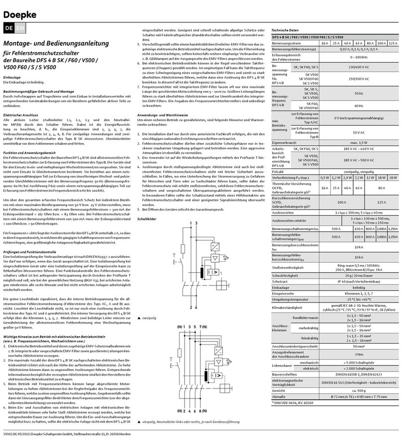
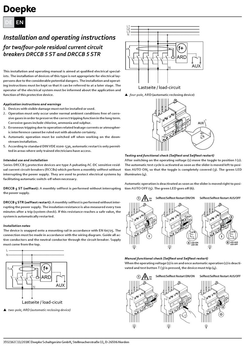
Wiring diagrams
N6
~
Vtwo-pole
~
Vfour-pole, neutral on left or right, depending on device version
Installation and Operating Manual
for two-/four-pole residual current circuit-breakers
in DFS 4 A EV model ranges
Intended use
vices that disconnect the switching contacts of the RCCB when smooth DC residual
currents > 6 mA are detected. They are only suitable as protective devices for the
Mounting
Mounting is carried out by snapping onto a mounting rail for installation in distri
bution boards with suitable device covers to prevent contact with dangerous active
parts.
Electrical connection
be used. Scrape and grease aluminium conductors immediately before connection.
Integrated additional device
The integrated additional device, which depends on the auxiliary voltage, detects
smooth DC residual currents. If these currents exceed 6 mA, the additional device
dicates that the additional device is active. The additional device is supplied via an
must be present at these terminals for the additional device to function properly. If
the LED does not illuminate, then only tripping via type A residual currents is still
guaranteed.
Testing and functional check
An insulation test of the user equipment is to be carried out in accordance with DIN
ing when the device is switched on or insulation testing on the input side may lead
breaker itself is possible with connected mains voltage by pressing the test button T
the case of stationary systems and should be repeated every working day in the case
Application instructions and warnings
The following notes and warnings must be observed in order to ensure safe opera
Installation may only be carried out by an electrician who is familiar with the rel
evant national installation regulations.
atmosphere must also be avoided.
The user must be made aware of repeat testing using the test button T.
thermal overload protection. Thermal overloading must be ruled out as a matter
Trips due to leakage currents caused by surge voltage cannot be completely ruled
out. In cases where an interruption of the power supply may lead to potential
dangers for humans and animals or serious damage to property, residual current
protection should be implemented by means of increased surge current strength,
Important information on tripping with pulsating DC residual currents (type A)
Pulsating DC residual currents also contain a constant part (DC) in addition to
tween a pure smooth DC residual current and the constant (DC), spectral part
of a pulsating DC residual current and thus evaluates these in the same way.
If the additional device is active, pulsating DC residual currents will therefore
Doepke
||
DE EN
