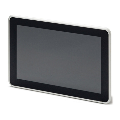
Phoenix Contact Basicline 2 Series User manual

User manual
UM EN BL2 ...100
Basicline 2 configurable industrial PCs

2020-02-14
PHOENIX CONTACT GmbH & Co. KG • Flachsmarktstraße 8 • 32825 Blomberg • Germany
phoenixcontact.com
4024_en_E
Basicline 2 configurable industrial PCs
BL2 BPC 1100 1105772
BL2 BPC 2100 1105773
BL2 BPC 3100 1105776
BL2 BPC 7100 1105777
BL2 BPC 9100 1105778
BL2 BPC 1101 1099299
BL2 BPC 2101 1099302
BL2 BPC 3101 1099306
BL2 BPC 7101 1099309
BL2 BPC 9101 1099311
BL2 PPC 2100 1105780
BL2 PPC 3100 1105781
BL2 PPC 7100 1105782
BL2 PPC 9100 1105783
BL2 PPC15.6 2101 1099318
BL2 PPC15.6 3101 1099319
BL2 PPC15.6 7101 1099320
BL2 PPC15.6 9101 1099321
BL2 PPC18.5 2101 1099324
BL2 PPC18.5 3101 1099325
BL2 PPC18.5 7101 1099327
BL2 PPC18.5 9101 1099328
BL2 PPC21.5 2101 1099331
BL2 PPC21.5 3101 1099332
BL2 PPC21.5 7101 1099333
BL2 PPC21.5 9101 1099334
User manual
This user manual is valid for:
UM EN BL2 ...100, Revision E

Table of contents
4024_en_E PHOENIX CONTACT 1/36
Table of contents
1 For your safety............................................................................................................................3
1.1 Labeling of warning notes......................................................................................3
1.2 Qualification of users .............................................................................................3
1.3 Field of application of the products ........................................................................3
1.3.1 Intended use ..........................................................................................3
1.3.2 Product changes ....................................................................................4
2 Overview and ordering data........................................................................................................5
2.1 Description ............................................................................................................5
2.2 Ordering data.........................................................................................................5
3 Installation...................................................................................................................................7
3.1 Mounting................................................................................................................7
3.1.1 Wall mount (BL2 BPC ...100) .................................................................7
3.1.2 DIN rail mount ........................................................................................9
3.1.3 Panel mount (BL2 PPC ...100) .............................................................10
3.2 Interfaces ............................................................................................................11
3.2.1 Power connection ................................................................................12
3.2.2 Serial communication ...........................................................................13
3.3 Antenna ...............................................................................................................14
4 Operation..................................................................................................................................15
4.1 LED operation......................................................................................................15
5 Maintenance.............................................................................................................................17
5.1 UEFI ....................................................................................................................17
5.2 Mass storage replacement ..................................................................................17
5.2.1 Accessing the drives ............................................................................18
5.2.2 SATA drive ...........................................................................................20
5.2.3 M.2 drive ..............................................................................................21
A Technical appendix...................................................................................................................23
A 1 Technical data .................................................................................................... 23
B Appendixes...............................................................................................................................29
B 1 List of figures ...................................................................................................... 29
B 2 List of tables ....................................................................................................... 31
B 3 Index................................................................................................................... 33

For your safety
4024_en_E PHOENIX CONTACT 3/36
1 For your safety
Read this user manual carefully and keep it to hand for future reference.
1.1 Labeling of warning notes
1.2 Qualification of users
The use of products described in this manual is oriented exclusively to electrically skilled
persons or persons instructed by them. The users must be familiar with the relevant safety
concepts of automation technology as well as applicable standards and other regulations.
1.3 Field of application of the products
1.3.1 Intended use
The products described in this document are designed for use in manufacturing and
industrial environments.
The products are built according to the latest safety requirements. However, dangerous
situations or damage to the products or other property can arise from misuse of this device.
The products fulfill the requirements of the EMC directives and harmonized European
standards Any modifications to the systems can influence the EMC behavior.
This symbol indicates hazards that could lead to personal injury.
There are three signal words indicating the severity of a potential injury.
DANGER
Indicates a hazard with a high risk level. If this hazardous situation is not
avoided, it will result in death or serious injury.
WARNING
Indicates a hazard with a medium risk level. If this hazardous situation is not
avoided, it could result in death or serious injury.
CAUTION
Indicates a hazard with a low risk level. If this hazardous situation is not avoided,
it could result in minor or moderate injury.
This symbol together with the NOTE signal word alerts the reader to a situation
which may cause damage or malfunction to the device, hardware/software, or
surrounding property.
Here you will find additional information or detailed sources of information.
The device contains valuable recyclable materials that should be utilized. The electronic
circuit board is fitted with a lithium battery.
Dispose of the device separately from other waste, i.e., via an appropriate collection site.

BL2 ...100
4/36 PHOENIX CONTACT 4024_en_E
Radio interference
These products are Class A items of equipment (EN 61000-6-4). When using the equipment
in residential areas, it may cause radio interference. In this case, the operator is obligated
to implement appropriate measures.
1.3.2 Product changes
Changes or modifications to hardware and software of the device are not permitted.
Incorrect operation or modifications to the device can endanger your safety or damage the
device. Do not repair the device yourself. If the device is defective, please contact
Phoenix Contact.

Overview and ordering data
4024_en_E PHOENIX CONTACT 5/36
2 Overview and ordering data
2.1 Description
The BL2 ...100 IPC is a configurable box PC (BPC) or panel PC (PPC) that utilizes the Intel®
processors chosen for their balance of processing power, graphic performance, and energy
efficiency. The robust design and I/O capability make the BL2 ...100 a product that can be
used in a wide variety of applications.
Features
– Compact, rugged housing
– Fanless design
– Intel®Core™ i7 processors available
– DIN rail- and wall-mount options
– Two integrated 10/100/1000 Ethernet ports with independent MAC addresses
– IP66 rating (front), IP20 rating (back)
– UEFI-configurable RS-232/422/485 communication port
– Up to 8 GB RAM
– USB 2.0 and 3.0 ports
2.2 Ordering data
Products
Description Type Order No. Pcs./Pkt.
Industrial box PC, configurable, Intel®Celeron®processor N3350
1.10/2.40 GHz
BL2 BPC 1100 1105772 1
Industrial box PC, configurable, Intel®Celeron®processor N4200
1.10/2.50 GHz
BL2 BPC 2100 1105773 1
Industrial box PC, configurable, Intel®Core™ i3-6100U processor
2.30 GHz
BL2 BPC 3100 1105776 1
Industrial box PC, configurable, Intel®Core™ i5-6300U processor
2.40/3.00 GHz
BL2 BPC 7100 1105777 1
Industrial box PC, configurable, Intel®Core™ i7-6600U processor
2.60/3.40 GHz
BL2 BPC 9100 1105778 1
Industrial box PC, Intel®Celeron®processor N3350 1.10/2.40 GHz BL2 BPC 1101 1105779 1
Industrial box PC, Intel®Celeron®processor N4200 1.10/2.50 GHz BL2 BPC 2101 1105780 1
Industrial box PC, Intel®Core™ i3-6100U processor 2.30 GHz BL2 BPC 3101 1105781 1
Industrial box PC, Intel®Core™ i5-6300U processor 2.40/3.00 GHz BL2 BPC 7101 1105782 1
Industrial box PC, Intel®Core™ i7-6600U processor 2.60/3.40 GHz BL2 BPC 9101 1105783 1
Industrial panel PC, configurable, Intel®Celeron®processor N4200
1.10/2.50 GHz
BL2 PPC 2100 1105780 1
Industrial panel PC, configurable, Intel®Core™ i3-6100U processor
2.30 GHz
BL2 PPC 3100 1105781 1
Industrial panel PC, configurable, Intel®Core™ i5-6300U processor
2.40/3.00 GHz
BL2 PPC 7100 1105782 1
Industrial panel PC, configurable, Intel®Core™ i7-6600U processor
2.60/3.40 GHz
BL2 PPC 9100 1105783 1
Industrial panel PC, with 15.6-in. display, Intel®Celeron®processor N4200
1.10/2.50 GHz
BL2 PPC 2100 1099318 1
Industrial panel PC, with 15.6-in. display, Intel®Core™ i3-6100U processor
2.30 GHz
BL2 PPC 3100 1099319 1

BL2 ...100
6/36 PHOENIX CONTACT 4024_en_E
Industrial panel PC, with 15.6-in. display, Intel®Core™ i5-6300U processor
2.40/3.00 GHz
BL2 PPC 7100 1099320 1
Industrial panel PC, with 15.6-in. display, Intel®Core™ i7-6600U processor
2.60/3.40 GHz
BL2 PPC 9100 1099321 1
Industrial panel PC, with 18.5-in. display, Intel®Celeron®processor N4200
1.10/2.50 GHz
BL2 PPC 2100 1099324 1
Industrial panel PC, with 18.5-in. display, Intel®Core™ i3-6100U processor
2.30 GHz
BL2 PPC 3100 1099325 1
Industrial panel PC, with 18.5-in. display, Intel®Core™ i5-6300U processor
2.40/3.00 GHz
BL2 PPC 7100 1099327 1
Industrial panel PC, with 18.5-in. display, Intel®Core™ i7-6600U processor
2.60/3.40 GHz
BL2 PPC 9100 1099328 1
Industrial panel PC, with 21.5-in. display, Intel®Celeron®processor N4200
1.10/2.50 GHz
BL2 PPC 2100 1099331 1
Industrial panel PC, with 21.5-in. display, Intel®Core™ i3-6100U processor
2.30 GHz
BL2 PPC 3100 1099332 1
Industrial panel PC, with 21.5-in. display, Intel®Core™ i5-6300U processor
2.40/3.00 GHz
BL2 PPC 7100 1099333 1
Industrial panel PC, with 21.5-in. display, Intel®Core™ i7-6600U processor
2.60/3.40 GHz
BL2 PPC 9100 1099334 1
Products [...]
Description Type Order No. Pcs./Pkt.
Accessories
Description Type Order No. Pcs./Pkt.
Service socket with USB (socket/plug), type A with 0.6 m cable SI-SES-U1A/0,6 1404514 1
Adapter, DisplayPort to VGA video adapter DP to VGA ADPTR 2400173 1
Adapter, DisplayPort to DVI-I video adapter DP to DVI ADPTR 2400174 1
Cable, DisplayPort to DisplayPort, 2 m VL 2.0M DP CABLE 2404774 1
Visit phoenixcontact.net/products for available accessories
Replacement parts
Description Type Order No. Pcs./Pkt.
Connector, printed circuit board connector MSTB 2,5/ 3-STF-5,08 1777992 1

Installation
4024_en_E PHOENIX CONTACT 7/36
3 Installation
3.1 Mounting
Depending upon the configuration ordered, there are several ways to mount the BL2 ...100.
Use the appropriate section below to mount the BL2 ...100.
When installing the BL2 ...100 in a cabinet, follow these general rules:
– Verify clearances within the cabinet. Typically, leave at least 5 cm (2 in.) on each side
with 13 cm (5 in.) on the connector side.
– Drill all holes and make all cuts before beginning installation. Be sure to protect already
installed components from shavings during this procedure.
– Supporting panels must be at least 14 gauge to provide proper support.
– Make sure that there is adequate space around the heat sink to provide sufficient
cooling.
3.1.1 Wall mount (BL2 BPC ...100)
Figure 3-1 Mounting dimensions (BL2 BPC 1100, BL2 BPC 2100)
NOTE:
Install the BL2 ...100 with adequate clearance around the heat sink to provide sufficient air
flow such that ambient temperatures do not exceed the operating limits. Install cooling
fan(s) in the enclosure, if necessary.
Connectors and switches must be accessible. A wall panel thickness of 1.9 mm (14 ga.)
is required for correct mounting of a BL2 PPC ...100 to maintain IP66 protection.
NOTE:
Exceeding the system temperature limits can result in performance degradation of any or
all components. It is therefore important that the ambient temperature of the installation
environment is kept within the system temperature limits of your BL2 ...100.
194
185
94
131

BL2 ...100
8/36 PHOENIX CONTACT 4024_en_E
Figure 3-2 Mounting dimensions (BL2 BPC 3100, BL2 BPC 7100, BL2 BPC 9100)
Installation
1. Use the BL2 BPC ...100 as a template (or the dimensions shown in Figure 3-1 or
Figure 3-2) and mark the locations of the holes on the mounting surface.
2. Use the correct anchor type for the mounting surface and securely attach the
BL2 BPC ...100 to the wall. Ensure that the attaching hardware is in the small section of
the keyholes.
Removal
1. Remove power and disconnect cables to the IPC.
2. Loosen and remove the screws securing the IPC to the mounting surface.
247
238
94
145

Installation
4024_en_E PHOENIX CONTACT 9/36
3.1.2 DIN rail mount
Figure 3-3 DIN rail mounting
1. Angle the BL2 BPC ...100 so the top edge of the mounting plate hangs on the top edge
of the DIN rail.
2. Rotate the BL2 BPC ...100 down (A) against the lower edge of the DIN rail. Press in (B)
until the latch snaps closed.
3. Secure the device on the rail with clamps.
4. If necessary to remove, raise the device straight up (A) and rotate the device away from
the rail (B).
NOTE:
Only the BL2 BPC 1100 and BL2 BPC 2100 has the option of DIN rail mounting.
A
A
A
AB
B
Mounting
Removal

BL2 ...100
10/36 PHOENIX CONTACT 4024_en_E
3.1.3 Panel mount (BL2 PPC ...100)
1. Cut a hole in the enclosure according to the dimensions for the selected display.
Figure 3-4 Panel cutout dimensions
Figure 3-5 Panel-mounting clamps
2. From the front, push the BL2 PPC ...100 through the opening, making sure the gasket
(1) is properly positioned in the groove and against the panel.
3. From the rear, place the clamps (2) in the slots (3) on the display and slide the clamp to
the left to lock it into the slot. Clamps must be installed in every slot.
4. Tighten the screw on each clamp, alternating from one side to the other until the front
bezel is secure against the mounting panel. Torque the screws to 1.2 Nm.
Table 3-1 Display cutout dimensions
Display size X (mm) Y (mm)
21.5 in. 547 367
18.5 in. 475 306
15.6 in. 401 296
X
Y
1
2
3

Installation
4024_en_E PHOENIX CONTACT 11/36
3.2 Interfaces
Figure 3-6 Connectors and ports (BL2 … 1100, BL2 … 2100)
Figure 3-7 Connectors and ports (BL2 … 3100, BL2 … 7100, BL2 … 9100)
After mounting the BL2 ...100, make any necessary cable connections (see Figure 3-6).
The available connectors are:
– Ethernet (ETH): Two RJ45 connectors allow the computer to communicate on a
10/100/1000 Base-T Ethernet network.
– Serial (COM): Three D-SUB 9 serial ports are available for use. Two ports are set as
RS-232 while one port is configurable as either RS-232, RS-422, or RS-485.
1Functional earth (ground) screw
2Power connector
3Ethernet RJ45 ports
4USB 3.0 connectors
5USB 2.0 connectors
6DisplayPort connectors
7On/off switch
8Configurable RS-232/422/485 serial port
9RS-232 serial ports
10 Status LEDs
11 Antenna mount location (optional)
DC24V
RS-232/422/485
12
SS
RS-232 RS-232
DP2 DP1
PG
23 456
910
7
11
81
1Functional earth (ground) screw
2Power connector
3Ethernet RJ45 ports
4USB 3.0 connectors
5USB 2.0 connectors
6DisplayPort connectors
7RS-232 serial ports
8On/off switch
9Configurable RS-232/422/485 serial port
10 Status LEDs
Antenna mount location (optional) (see
Figure 3-9)
DC24V
RS-232/422/485
12 SS RS-232 RS-232
DP1 DP2
PG
2
1
34567 8
910

BL2 ...100
12/36 PHOENIX CONTACT 4024_en_E
– USB (USB): USB devices connect using Type A connectors. Two ports are USB 2.0
and two are USB 3.0 ports.
– DisplayPort (DP): These ports connect the BL2 ...100 to external digital displays with a
corresponding DP++ connector.
– Antenna port: Optional port for installation of an antenna (see “Antenna” on page 14).
External display
External displays can be connected to the DP ports of the BL2 ...100.
– The BL2 BPC ...100 supports up to three external displays.
– The BL2 PPC ...100 supports up to two external displays.
3.2.1 Power connection
A three-position, screw-type COMBICON connector (MSTB 2,5/ 3-STF-5,08) is provided
for connecting power to the BL2 ...100.
Figure 3-8 Power connector
Connect a power source to the included power connector (1). This connector supports wire
sizes from 0.2 to 2.5 mm² (24 to 12 AWG). Torque the wire-retaining screws in the
connector to 0.5 Nm (4.4 lbf-in.). Secure the connector to the BL2 ...100 chassis.
USB 3.0 ports utilize a blue connector. USB 2.0 ports are black.
Table 3-2 Power connector
Pin No. Description
Functional earth (ground)
– 0 V DC
+ 24 V DC ±20%
DC24V
RS-232/422/4
1
2
3

Installation
4024_en_E PHOENIX CONTACT 13/36
A separate FE connection is required to satisfy UL requirements. Place the functional earth
(ground) wire (2) under the ground screw (3) using a ring terminal connection. Torque screw
to 1.2 Nm.
3.2.2 Serial communication
One D-SUB 9 connector (see Figure 3-6 or Figure 3-7) can be configured to communicate
on the RS-232, RS-422, or RS-485 physical layer. The physical layer is set using the UEFI
(see “UEFI” on page 17). The remaining connectors are limited to RS-232 only.
The BL2 ...100 is capable of the following communication parameters:
The function of the pins in the D-SUB 9 connector varies with the different configuration
settings.
NOTE:
To comply with UL 61010-2-201, a safety extra-low voltage (SELV) according to DIN EN
61131 as supply voltage is required.
This device is protection class I item of equipment.
UEFI is set to boot on power, allowing the system to boot as soon as the power plug is
installed. This can be changed in the UEFI Setup Utility.
Table 3-3 RS-232/422/485 communication settings
Data bits Parity Stop bits
RS-232 7/8 None/Even/Odd 1/2
RS-422/485 Autotoggle RTS 8 None/Even/Odd 1/2
RS-422/485 Manual RTS 7/8 None/Even/Odd 1/2
The table shows the capabilities of the IPC. Configuration of parameters to communicate
with a specific device is typically part of the software tool performing the communication.
Table 3-4 D-SUB 9 pinout
D-SUB 9 pin RS-232 RS-422 RS-485
1 DCD TXD- TXD-/RXD-
2 RXD TXD+ TXD+/RXD+
3 TXD RXD+ –
4 DTR RXD- –
5 GND GND GND
6 DSR – –
7 RTS – –
8 CTS – –
9 Ring indicator – –

BL2 ...100
14/36 PHOENIX CONTACT 4024_en_E
3.3 Antenna
An optional factory-installed mini PCIe card is available to allow the BL2 ...100 to be placed
on a wireless network. Included with the installed card is an antenna (1) that attaches to a
connector on the top of the unit (2).
Figure 3-9 Antenna installation (BL2 BPC 3100 shown)
Since the BL2 ...100 is often installed within an enclosure, it may be advisable to install the
antenna on the exterior of the enclosure rather than directly to the IPC. To do this, an
appropriate length antenna cable (3) must be purchased separately.
The antenna (or antenna cable) threads onto the BL2 ...100. For external antenna
mounting, route and secure the antenna cable appropriately within the enclosure.
The BL2 … 1100 and BL2 … 2100 have one antenna connector on the top and one on the
bottom (see “Connectors and ports (BL2 … 1100, BL2 … 2100)” on page 11). The top
connector is unaccessible if the DIN rail mounting method is used and the bottom
connector must be used.
1
3
4
2
NOTE:
Do not allow metal chips to fall within the enclosure when creating the hole for mounting
the antenna.

Operation
4024_en_E PHOENIX CONTACT 15/36
4 Operation
4.1 LED operation
Four LEDs are provided on the BL2 ...100. These LEDs provide operating information (see
Figure 3-6 on page 11).
Table 4-1 LED indications
LED Indication Description
PWR Green When 24 V DC is applied and the power switch is
turned on
SATA Flashes green Indicates data storage (HDD or SSD) activity
RUN Reserved for future use
ERROR Orange
Red
Indicates processor is actively thermal throttling
Indicates processor has shut down due to
overheating

Maintenance
4024_en_E PHOENIX CONTACT 17/36
5 Maintenance
5.1 UEFI
The unified extensible firmware interface (UEFI) configures the software to match the
hardware contained within the industrial PC.
To access the UEFI setup utility, there must be an actual (physical) keyboard attached to
one of the USB ports.
During the boot process, press the <F2> key to enter the UEFI setup utility. Use the arrow
keys to navigate and highlight desired selections. Follow on-screen instructions and be sure
to save any changes.
One-time change to the boot sequence
A quick-boot menu allows changes to the boot sequence one time. This can be used to load
a new operating system from a USB drive.
1. Press the <F7> key during the boot process to access the quick-boot menu.
2. Highlight the device from which to boot.
3. Press the <Enter> key to initiate the boot process.
5.2 Mass storage replacement
Before beginning any mass storage replacement procedures, use an external drive and
make a copy of or backup the contents of the internal drive to be replaced. Disconnect the
external drive before removing power to the BL2 ...100.
NOTE: Electrostatic discharge
Electrostatic discharge can damage or destroy components. When handling, observe the
necessary safety precautions against electrostatic discharge (ESD) according to
EN 61340-5-1 and IEC 61340-5-1.
NOTE:
Changing UEFI parameters can lead to system instability and data loss. Therefore, it is
recommended that only advanced users modify the UEFI settings.
A device must be connected before applying power to be displayed as a selectable
device.
WARNING:
Always remove power to the IPC and any connected devices before performing internal
maintenance.
NOTE:
The device contains components that can be damaged or destroyed by electrostatic
discharge. When handling the device, observe the necessary safety precautions against
electrostatic discharge (ESD) according to EN 61340-5-1 and IEC 61340-5-1.

BL2 ...100
18/36 PHOENIX CONTACT 4024_en_E
5.2.1 Accessing the drives
BL2 BPC ...100
1. Remove the BL2 BPC ...100 from it’s mounting location and place it on a clean,
horizontal surface. It is not necessary to remove the mounting brackets.
Figure 5-1 Access panel
2. Remove the six screws (1) securing the access panel (2) to the chassis.
3. Gently pry the access panel away from the chassis using a flat screwdriver. Turn the
access panel over to protect the thermal pads (3) and set aside.
The drive tray should be visible inside the chassis.
4. Replace any desired components.
5. To reinstall, place the access panel on the chassis, making sure no cables are pinched.
Secure the panel using the hardware previously removed.
Figure 1
1
2
3
NOTE:
Two sticky-backed thermal pads are located between the access panel and drive tray.
Other manuals for Basicline 2 Series
2
Table of contents
Other Phoenix Contact Industrial PC manuals