Phoenix Contact Basicline 2 Series User manual

User manual
UM EN BL2 1000/2000/7000
Basicline 2 configurable industrial PCs

2018-09-06
PHOENIX CONTACT GmbH & Co. KG • Flachsmarktstraße 8 • 32825 Blomberg • Germany
phoenixcontact.com
3799_en_D
Basicline 2 configurable industrial PCs
Designation Order No.
BL2 BPC 1000 2404777
BL2 PPC 1000 2404845
BL2 BPC 2000 2404844
BL2 PPC 2000 2404846
BL2 BPC 7000 1016240
BL2 PPC 7000 1016236
User manual
This user manual is valid for:
UM EN BL2 1000/2000/7000, Revision D

Table of contents
3799_en_D PHOENIX CONTACT 1/36
Table of contents
1 For your safety............................................................................................................................3
1.1 Labeling of warning notes......................................................................................3
1.2 Qualification of users .............................................................................................3
1.3 Field of application of the products ........................................................................3
1.3.1 Intended use ..........................................................................................3
1.3.2 Product changes ....................................................................................4
2 Overview and ordering data........................................................................................................5
2.1 Description ............................................................................................................5
2.2 Ordering data.........................................................................................................5
3 Installation...................................................................................................................................7
3.1 Mounting................................................................................................................7
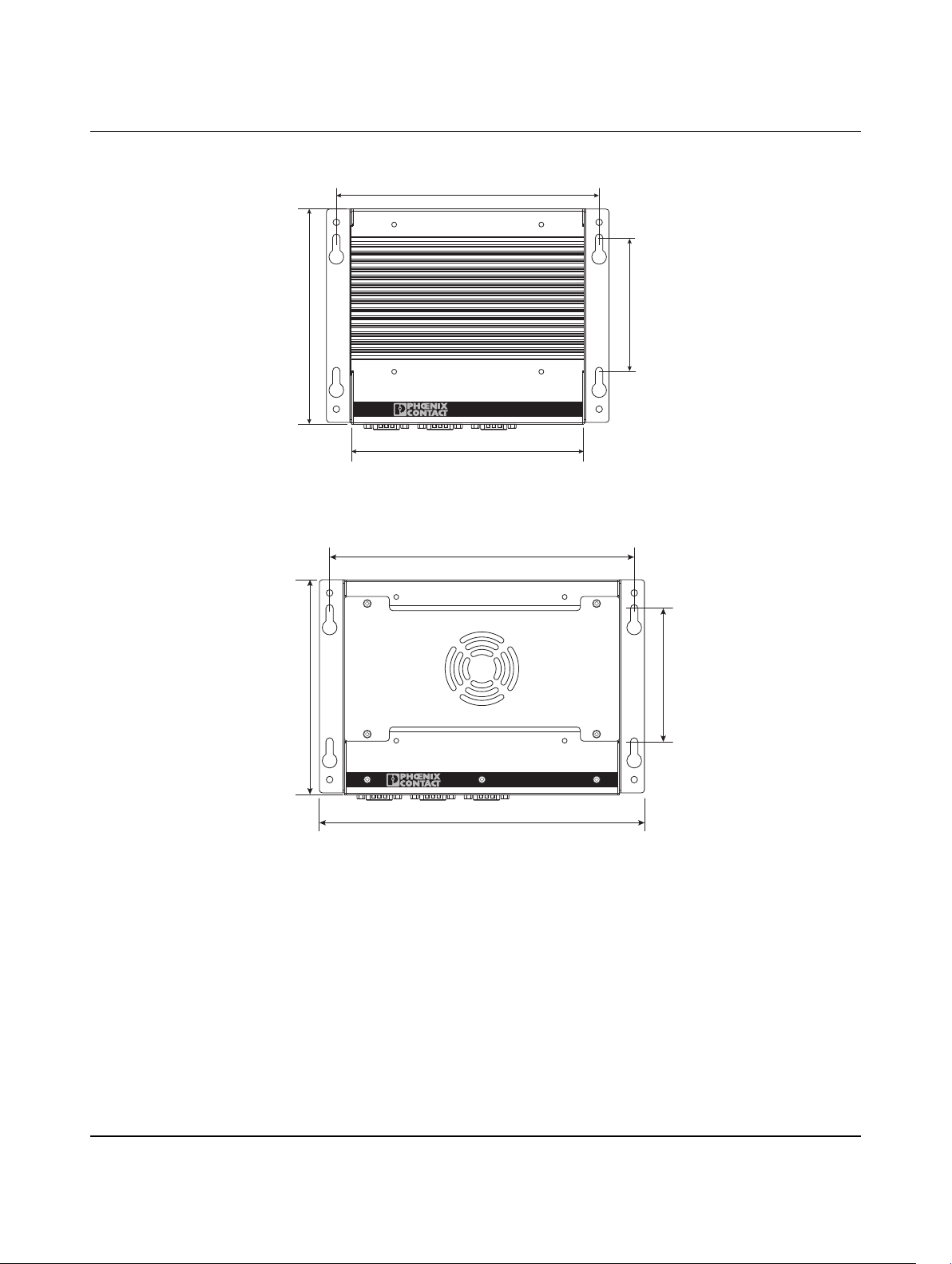
3.1.1 Wall mount (BL2 BPC ...) ......................................................................8
3.1.2 DIN rail mount (BL2 BPC ...) ..................................................................9
3.1.3 Panel mount (BL2 PPC ...) ...................................................................10
3.2 Interfaces ............................................................................................................11
3.2.1 Power connection ................................................................................12
3.2.2 Serial communication ...........................................................................13
3.3 Antenna ...............................................................................................................14
4 Operation..................................................................................................................................15
4.1 LED operation......................................................................................................15
5 Maintenance.............................................................................................................................17
5.1 Service panel.......................................................................................................17
5.1.1 Service panel (BL2 BPC ...) .................................................................17
5.1.2 Service panel (BL2 PPC ...) .................................................................18
5.2 Real-time clock battery ........................................................................................18
5.2.1 Battery disposal ..................................................................................20
5.3 CMOS/UEFI reset................................................................................................20
5.4 Mass storage.......................................................................................................21
5.5 UEFI ....................................................................................................................22
A Technical appendix...................................................................................................................23
A 1 Technical data .................................................................................................... 23

BL2 ...1000/2000/7000
2/36 PHOENIX CONTACT 3799_en_D
B Appendixes...............................................................................................................................29
B 1 List of figures ...................................................................................................... 29
B 2 List of tables ....................................................................................................... 31
B 3 Index................................................................................................................... 33

For your safety
3799_en_D PHOENIX CONTACT 3/36
1 For your safety
Read this user manual carefully and keep it to hand for future reference.
1.1 Labeling of warning notes
1.2 Qualification of users
The use of products described in this manual is oriented exclusively to electrically skilled
persons or persons instructed by them. The users must be familiar with the relevant safety
concepts of automation technology as well as applicable standards and other regulations.
1.3 Field of application of the products
1.3.1 Intended use
The products described in this document are designed for use in manufacturing and
industrial environments.
The products are built according to the latest safety requirements. However, dangerous
situations or damage to the products or other property can arise from misuse of this device.
The products fulfill the requirements of the EMC directives and harmonized European
standards Any modifications to the systems can influence the EMC behavior.
This symbol indicates hazards that could lead to personal injury.
There are three signal words indicating the severity of a potential injury.
DANGER
Indicates a hazard with a high risk level. If this hazardous situation is not
avoided, it will result in death or serious injury.
WARNING
Indicates a hazard with a medium risk level. If this hazardous situation is not
avoided, it could result in death or serious injury.
CAUTION
Indicates a hazard with a low risk level. If this hazardous situation is not avoided,
it could result in minor or moderate injury.
This symbol together with the NOTE signal word alerts the reader to a situation
which may cause damage or malfunction to the device, hardware/software, or
surrounding property.
Here you will find additional information or detailed sources of information.
The device contains valuable recyclable materials, which should be utilized. The
electronic circuit board is fitted with a lithium battery.
Dispose of the device separately from other waste, i.e., via an appropriate collection site.

BL2 ...1000/2000/7000
4/36 PHOENIX CONTACT 3799_en_D
Radio interference
These products are Class A items of equipment (EN 61000-6-4). When using the equipment
in residential areas, it may cause radio interference. In this case, the operator is obligated
to implement appropriate measures.
1.3.2 Product changes
Changes or modifications to hardware and software of the device are not permitted.
Incorrect operation or modifications to the device can endanger your safety or damage the
device. Do not repair the device yourself. If the device is defective, please contact
Phoenix Contact.

Overview and ordering data
3799_en_D PHOENIX CONTACT 5/36
2 Overview and ordering data
2.1 Description
The BL2 ...1000/2000/7000 IPC is a configurable box PC (BPC) or panel PC (PPC) that
utilizes the Intel®processors chosen for their balance of processing power, graphic
performance, and energy efficiency. The robust design and I/O capability make the
BL2 ...1000/2000/7000 a product that can be used in a wide variety of applications.
Features
– Compact, rugged housing
– Fanless design available
– Intel®Core™ i5 processors available
– DIN rail- and wall-mount options
– Two integrated 10/100/1000 Ethernet ports with independent MAC addresses
– IP65 rating (front), IP20 rating (back)
– UEFI-configurable RS-232/422/485 communication port
– Up to 8 GB RAM
– USB 2.0 and 3.0 ports
2.2 Ordering data
Products
Description Type Order No. Pcs./Pkt.
Industrial box PC, configurable, Intel®Celeron®processor N3350
1.10/2.40 GHz
BL2 BPC 1000 2404777 1
Industrial panel PC, configurable, Intel®Celeron®processor N3350
1.10/2.40 GHz
BL2 PPC 1000 2404845 1
Industrial box PC, configurable, Intel®Pentium®N4200 processor
1.10/2.50 GHz
BL2 BPC 2000 2404844 1
Industrial panel PC, configurable, Intel®Pentium®N4200 processor
1.10/2.50 GHz
BL2 PPC 2000 2404846 1
Industrial box PC, configurable, Intel®Core™ i5-7442EQ processor
2.10/2.90 GHz
BL2 BPC 7000 1016240 1
Industrial panel PC, configurable, Intel®Core™ i5-7442EQ processor
2.10/2.90 GHz
BL2 PPC 7000 1016236 1
Accessories
Description Type Order No. Pcs./Pkt.
Service socket with USB (socket/plug), type A with 0.6 m cable SI-SES-U1A/0,6 1404514 1
Adapter, DisplayPort to VGA video adapter DP to VGA ADPTR 2400173 1
Adapter, DisplayPort to DVI-I video adapter DP to DVI ADPTR 2400174 1
Cable, DisplayPort to DisplayPort, 2 m VL 2.0M DP CABLE 2404774 1
Visit phoenixcontact.net/products for available accessories
Replacement parts
Description Type Order No. Pcs./Pkt.
Connector, printed circuit board connector MSTB 2,5/ 3-STF-5,08 1777992 1

Installation
3799_en_D PHOENIX CONTACT 7/36
3 Installation
3.1 Mounting
Depending upon the configuration ordered, there are several ways to mount the
BL2 ...1000/2000/7000. Use the appropriate section below to mount the
BL2 ...1000/2000/7000.
When installing the BL2 ...1000/2000/7000 in a cabinet, follow these general rules:
– Verify clearances within the cabinet. Typically, leave at least 5 cm (2 in.) on each side
with 13 cm (5 in.) on the connector side.
– Drill all holes and make all cuts before beginning installation. Be sure to protect already
installed components from shavings during this procedure.
– Supporting panels must be at least 14 gauge to provide proper support.
– Make sure that there is adequate space around the heat sink to provide sufficient
cooling.
NOTE:
Install the BL2 ...1000/2000/7000 with adequate clearance around the heat sink to provide
sufficient air flow such that ambient temperatures do not exceed the operating limits.
Install cooling fan(s) in the enclosure, if necessary.
VESA mounting holes are available for the BL2 … 1000 and BL2 … 2000. However,
mounting the BL2…7000 using the VESA mounts will restrict airflow through the
convection booster and void any warranty.
Connectors and switches must be accessible. A wall panel thickness of 1.9 mm (14 ga.)
is required for correct mounting of a BL2 PPC ... to maintain IP65 protection.
NOTE:
Exceeding the system temperature limits can result in performance degradation of any or
all components. It is therefore important that the ambient temperature of the installation
environment is kept within the system temperature limits of your BL2 ...1000/2000/7000.

BL2 ...1000/2000/7000
8/36 PHOENIX CONTACT 3799_en_D
3.1.1 Wall mount (BL2 BPC ...)
Figure 3-1 Mounting dimensions (BL2 BPC 1000, BL2 BPC 2000)
Figure 3-2 Mounting dimensions (BL2 BPC 7000)
Installation
1. Use the BL2 BPC ... as a template (or the dimensions shown in Figure 3-1 or
Figure 3-2) and mark the locations of the holes on the mounting surface.
2. Use the correct anchor type for the mounting surface and securely attach the
BL2 BPC ... to the wall. Ensure that the attaching hardware is in the small section of the
keyholes.
Removal
1. Remove power and disconnect cables to the IPC.
2. Loosen and remove the screws securing the IPC to the mounting surface.
178
161
90
146
207
186
90
146

Installation
3799_en_D PHOENIX CONTACT 9/36
3.1.2 DIN rail mount (BL2 BPC ...)
Figure 3-3 DIN rail mounting
1. Angle the BL2 BPC ... so the top edge of the mounting plate hangs on the top edge of
the DIN rail.
2. Rotate the BL2 BPC ... down against the lower edge of the DIN rail. Press in until the
latch snaps closed.
3. Secure the device on the rail with clamps.
4. If necessary to remove, use a screwdriver to release the latch and rotate the device
away from the rail.

BL2 ...1000/2000/7000
10/36 PHOENIX CONTACT 3799_en_D
3.1.3 Panel mount (BL2 PPC ...)
1. Cut a hole in the enclosure according to the dimensions for the selected display.
Figure 3-4 Panel cutout dimensions
Figure 3-5 Panel-mounting clamps
2. From the front, push the BL2 PPC ... through the opening, making sure the gasket (1)
is properly positioned in the groove and against the panel.
3. From the rear, place the clamps (2) in the slots (3) on the display and slide the clamp to
the left to lock it into the slot. Clamps must be installed in every slot.
4. Thread a screw (4) into every clamp. Tighten the screw on each clamp, alternating from
one side to the other until the front bezel is secure against the mounting panel. Torque
the screws to 0.88 Nm.
Table 3-1 Display cutout dimensions
Display size X (mm) Y (mm)
12 in. 334.0 253.0
15 in. 386.6 285.6
17 in. 424.0 329.5
X
Y
3
1
2
4

Installation
3799_en_D PHOENIX CONTACT 11/36
3.2 Interfaces
Figure 3-6 Connectors and ports
After mounting the BL2 ...1000/2000/7000, make any necessary cable connections (see
Figure 3-6).
The available connectors are:
– Ethernet (ETH): Two RJ45 connectors allow the computer to communicate on a
10/100/1000 Base-T Ethernet network.
– Serial (COM): Three D-SUB 9 serial ports are available for use. Two ports are set as
RS-232 while one port is configurable as either RS-232, RS-422, or RS-485.
– USB (USB): USB devices connect using Type A connectors. Two ports are USB 2.0
and two are USB 3.0 ports.
– DisplayPort (DP): These ports connect the BL2 ...1000/2000/7000 to external digital
displays with a corresponding DP++ connector.
– Mini PCIe: This internal slot allows installation of a mini PCIe card (see “Mass storage”
on page 21).
External display
External displays can be connected to the DP ports of the BL2 ...1000/2000/7000. The
BL2 BPC ... supports up to three external displays and the BL2 PPC ... supports up to two
external displays.
1Power connector
2Ethernet RJ45 ports
3USB 3.0 connectors
4USB 2.0 connectors
5DisplayPort connectors
6Configurable RS-232/422/485 serial port
7RS-232 serial ports
8Status LEDs
12345
6789
X11: COM
X10: COM X12: COM
X8: DPX9: DP X6: USB
X7: USB
X4: USB
X5: USB X2: ETH
ERROR RUN SATA PWR
X1: PWR 24VDC
X3: ETH
1
6 87
325 4
USB 3.0 ports utilize a blue connector. USB 2.0 ports are black.

BL2 ...1000/2000/7000
12/36 PHOENIX CONTACT 3799_en_D
3.2.1 Power connection
A three-position, screw-type COMBICON connector (MSTB 2,5/ 3-STF-5,08) is provided
for connecting power to the BL2 ...1000/2000/7000.
Figure 3-7 Power connector
Connect a power source to the included power connector. This connector supports wire
sizes from 0.2 to 2.5 mm² (24 to 12 AWG). Torque the wire-retaining screws in the
connector to 0.5 Nm (4.4 lbf-in.). Secure the connector to the BL2 ...1000/2000/7000
chassis.
Table 3-2 Power connector
Pin No. Description
6Ground
– 0 V DC
+ 24 V DC ±20%
X11: COMX12: COM
X4: USB
X5: USB X2: ETH
ERROR RUN SATAPWR
X1: PWR24VDC
X3: ETH
NOTE:
To ensure safe operation, use safety extra-low voltage (SELV) according to DIN EN 61131
as supply voltage.
This device is protection class I item of equipment.
UEFI is set to boot on power, allowing the system to boot as soon as the power plug is
installed. This can be changed in the UEFI.

Installation
3799_en_D PHOENIX CONTACT 13/36
3.2.2 Serial communication
One D-SUB 9 connector (see Figure 3-6) can be configured to communicate on the
RS-232, RS-422, or RS-485 physical layer. The physical layer is set using the UEFI (see
“UEFI” on page 22). The remaining connectors are limited to RS-232 only.
The BL2 ...1000/2000/7000 is capable of the following communication parameters:
The function of the pins in the D-SUB 9 connector varies with the different configuration
settings.
Table 3-3 RS-232/422/485 communication settings
Data bits Parity Stop bits
RS-232 7/8 None/Even/Odd 1/2
RS-422/485 Autotoggle RTS 8 None/Even/Odd 1/2
RS-422/485 Manual RTS 7/8 None/Even/Odd 1/2
The table shows the capabilities of the IPC. Configuration of parameters to communicate
with a specific device is typically part of the software tool performing the communication.
Table 3-4 D-SUB 9 pinout
D-SUB 9 pin RS-232 RS-422 RS-485
1 DCD TXD- TXD-/RXD-
2 RXD TXD+ TXD+/RXD+
3 TXD RXD+ –
4 DTR RXD- –
5 GND GND GND
6 DSR – –
7 RTS – –
8 CTS – –
9 Ring indicator – –

BL2 ...1000/2000/7000
14/36 PHOENIX CONTACT 3799_en_D
3.3 Antenna
An optional factory-installed mini PCIe card is available to allow the BL2 ...1000/2000/7000
to be placed on a wireless network. Included with the installed card is an antenna (1) that
attaches to a connector on the side of the unit (2).
Figure 3-8 Antenna installation
Since the BL2 ...1000/2000/7000 is often installed within an enclosure, it may be advisable
to install the antenna on the exterior of the enclosure rather than directly to the IPC. To do
this, an appropriate length antenna cable (3) must be purchased separately.
The antenna or antenna threads onto the BL2 ...1000/2000/7000. For external antenna
mounting, route and secure the antenna cable appropriately within the enclosure.
1
3
2
NOTE:
Do not allow metal chips to fall within the enclosure when creating the hole for mounting
the antenna.

Operation
3799_en_D PHOENIX CONTACT 15/36
4 Operation
4.1 LED operation
Four LEDs are provided on the BL2 ...1000/2000/7000. These LEDs provide operating
information (see Figure 3-6 on page 11).
Table 4-1 LED indications
LED Indication Description
PWR Green When 24 V DC is applied and the power switch is
turned on
SATA Flashes green Indicates data storage (HDD or SSD) activity
RUN Reserved for future use
ERROR Orange
Red
Indicates processor is actively thermal throttling
Indicates processor has shut down due to
overheating

Maintenance
3799_en_D PHOENIX CONTACT 17/36
5 Maintenance
5.1 Service panel
The BL2 BPC ... has a removable service panel that allows access to the mini PCIe card
slot, configuration jumpers, and battery. To access these components on the BL2 PPC ...,
the display must be separated from the case.
5.1.1 Service panel (BL2 BPC ...)
1. Remove power from the BL2 BPC ....
2. Disconnect any cables, such as USB, Ethernet, etc., attached to the unit.
3. Loosen the mounting hardware securing the unit to the wall. Slide the BL2 BPC ...
upward and off (through the wide portion of key hole slot).
4. Place the unit on a flat surface with the heat sink down.
Figure 5-1 Component access via service panel
5. Loosen and remove the four screws (1) that hold the service panel (2) to the case and
remove the panel.
NOTE: Electrostatic discharge
Electrostatic discharge can damage or destroy components. When handling, observe the
necessary safety precautions against electrostatic discharge (ESD) according to
EN 61340-5-1 and IEC 61340-5-1.
LOCK
OPEN
X1: PWR 24VDC
X11:COM
X10: COMX12: COM
X6:USB
X7: USB
X4:USB
X5:USBX2: ETH
X3:ETH
ERRORRUNSAT
AP
WR
X8:DP
X9:DP
CR 2032
3V
1
2

BL2 ...1000/2000/7000
18/36 PHOENIX CONTACT 3799_en_D
5.1.2 Service panel (BL2 PPC ...)
1. Remove power from the BL2 PPC ....
2. Disconnect any cables, such as USB, Ethernet, etc., attached to the unit.
3. Remove the four screws (1) securing the case (2) to the back of the display panel (3).
Figure 5-2 Component access via display panel removal
4. Gently separate the case from the display, taking care to not separate the pieces so far
that tension is placed on the connecting cable (4). Do not unplug the connecting cable.
5.2 Real-time clock battery
The battery supplies power to the real-time clock (RTC) and maintains the UEFI settings in
the BL2 ...1000/2000/7000 when the system is not connected to a 24 V DC power source.
If power is removed while the battery is discharged or removed, any user-defined UEFI
settings will be lost, and a “CMOS checksum error” message appears once power is
restored.
To account for user-defined UEFI settings, it is recommended that they be recorded through
photos or a separate document before the battery is depleted or removed. Store the photos
or documents on a different device so they are accessible in the event of a boot failure.
The battery is type BR2032. The battery has a typical life of five years and may require
replacement.
CR 2032
3V
1
2
3
4
NOTE:
The cable between the case and display panel is glued into the connectors at both ends.
If unplugged at either end, the IPC no longer meets the specified shock and vibration
conformance levels.
Other manuals for Basicline 2 Series
2
This manual suits for next models
9
Table of contents
Other Phoenix Contact Industrial PC manuals
Popular Industrial PC manuals by other brands

Acrosser Technology
Acrosser Technology ACS-N0831FLUD installation guide

AXIOMTEK
AXIOMTEK tBOX322-882-FL Quick installation guide

Commell
Commell CMB-B72 installation guide

Star Lake
Star Lake SR700-X3 user manual

VIA Technologies
VIA Technologies AMOS-3000 user manual

Contec
Contec BX-825D Series Product guide