Phoenix Contact QUINT-DC-UPS/24DC/40 User manual

1.
Short Description
Uninterruptib
le Power Supply Units for Buffering
Long-Term Power Interruptions
•
Saves space thanks to the compact, uniform design
• Integrated diode saves money through isolation of
loads
• Maximum system availability through optimum
battery management and reliable signaling
• Minimum installation time due to ready-to-use
plug-in bridges and integrated timeout
QUINT-DC-UPS uninterruptible power supply units
with long-life lead-acid batteries provide long buffer
times at high currents. Even in the event of a longer
supply voltage failure, the units ensure that all
connected devices continue to operate without
interruption.
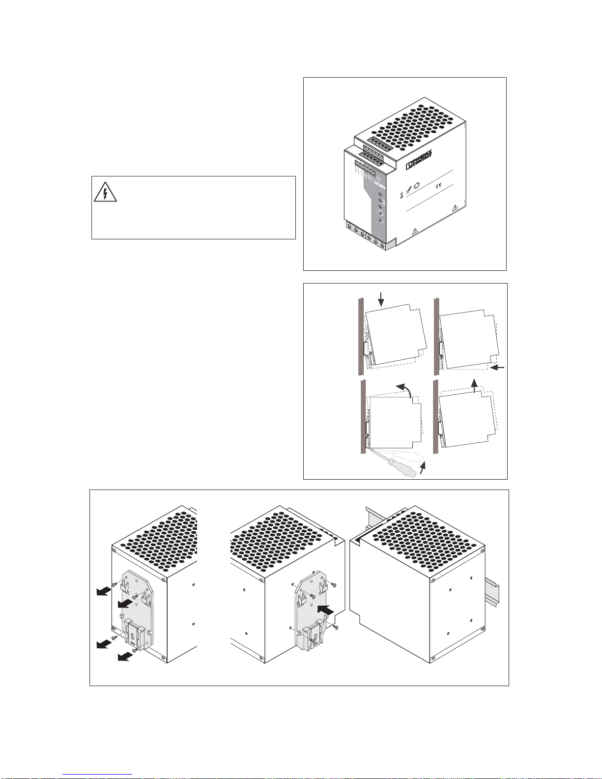
The devices have a narrow and uniform design,
which makes them ideal for use on the DIN rail where
space is limited. In addition, short wiring paths ensure
order and clarity in the control cabinet.
The high level of availability and the particularly long
service life of the battery modules are achieved
through professional battery management. An
automatic presence check (every minute), automatic
quality test (once a week), temperature-determined
charging, and electronic overcurrent protection ensure
the battery modules are ready to operate at all times.
Power is therefore available in the event of an error and
the service life of the battery module is maximized.
The actual state must be determined quickly so that
the right decision can be made in an emergency.
Optimum signaling is thus required for maximum
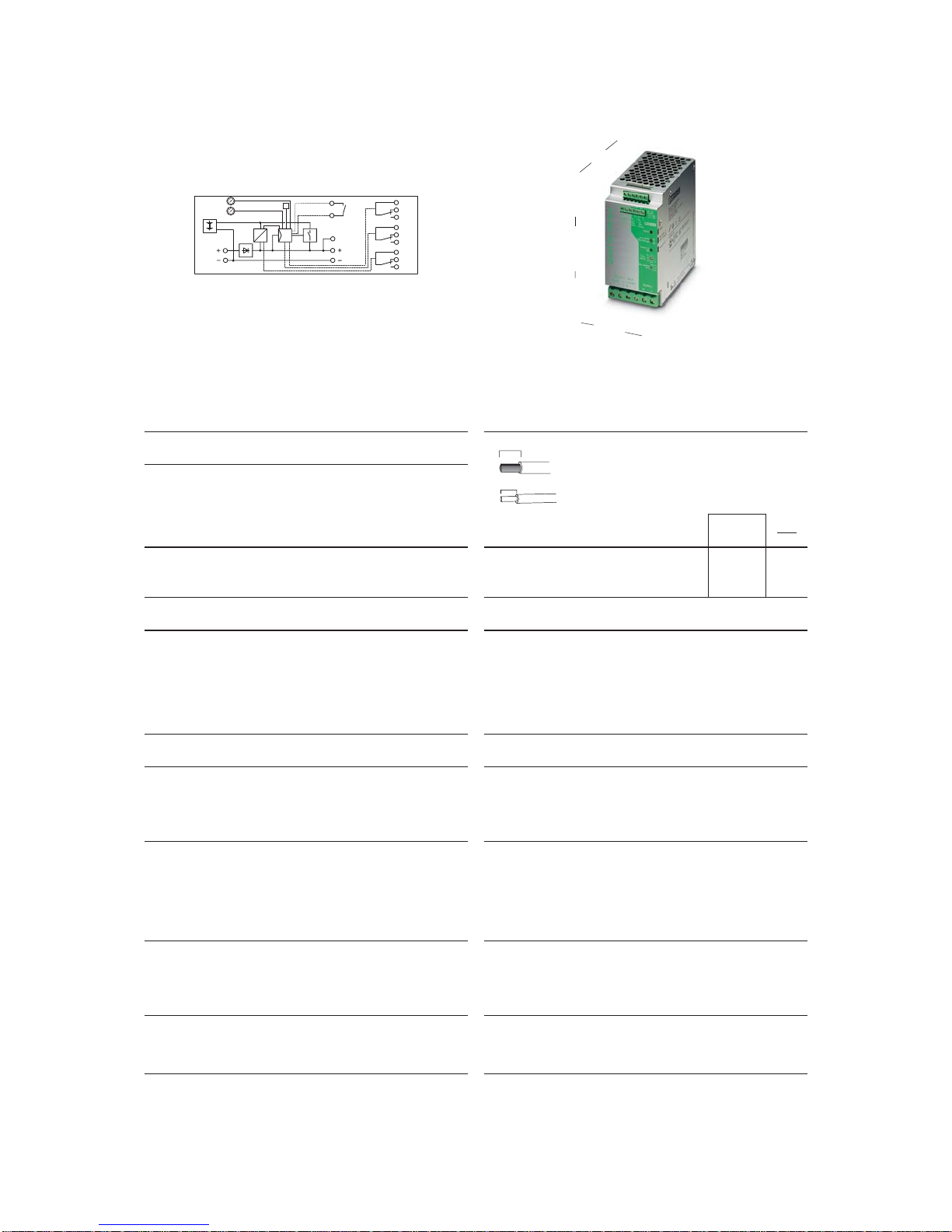
system availability. Three floating PDT contacts and
three LEDs are provided for function monitoring, which
indicate all the operating states clearly.
So that relay signaling is more reliable and more
durable than before, an additional positive supply
output has been provided. The contact, which is
current-limited and resistant to continued short circuits,
is located next to the relay connections and enables
easy bridging. In the event of wiring errors, the short-
circuit protection prevents any welding of the relay
contacts. This ensures that the user can rely on an OK
signal. Even in the event of connection errors, currents
remain below 100 mA, which prevents damage to the
relay contacts.
A system is switched off after a specific time that can
be set on the device or by an external signal. No
additional installation is required for shutdown. In
addition, ready-to-use plug-in bridges minimize the
installation time.
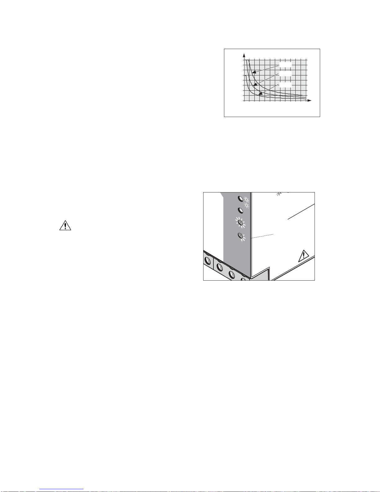
The connected devices can be divided into buffered
and unbuffered loads using the isolated input. This
extends the buffer time, which depends on the output
current. If only critical devices are protected using
fuses, smaller battery modules can be used that save
money and space in the control cabinet. In addition, the
isolated input protects the connected devices against
errors in the internal network.
Uninterruptib
le Power Supply Unit
for Universal Use QUINT-DC-UPS/24DC/40
Headquar
ters: © Phoenix Contact GmbH & Co. KG • Flachsmarktstraße 8 • 32825 Blomberg • Germany
Phone +49 - 52 35 - 30 0 • Fax +49 - 52 35 - 34 12 00 • www.phoenixcontact.com
Local Contact: www.phoenixcontact.com/salesnetwork

PHOENIX CONT
A
CT page
2
of
9
Solid
Str
anded
T
orque
[mm
2
]
A
WG
[Nm]
[
lb in]
Input
0.5 - 16
0.5 - 10
20 - 6
1.2 - 1.5
10.6 - 13.3
Output
0.5 - 16
0.5 - 10
20 - 6
1.2 - 1.5
10.6 - 13.3
Signal
0.2 - 2.5
0.2 - 2.5
25 - 14
0.5 - 0.6
4.5 - 5.3
Descr
iption
Uninterr
uptib
le
po
wer suppl
y unit
3.4 Ah batter
y module
7.2 Ah batter
y module
12 Ah batter
y module
T
ec
hnical Data
Input Data
Nominal input v
oltage
Input v
oltage r
ange
Current consumption (No load/charging/maxim
um)
Switching threshold
Buff
er time Can be confi
gured
Input fuse
Maxim
um po
w
er dissipation (Ready/b
uff
er mode)
Output Data
Can be connected in par
allel (batter
y module)
Output Data in Normal Operation
Nominal output v
oltage
Output v
oltage
Output current
Current limit
Ov
er
load fuse
Output Data in Buff
er Mode
Nominal output v
oltage
Output v
oltage Maxim
um
Output current
Current limit
Ov
er
load fuse
Le
v
el of effi
ciency
T
ypical
Remote shutdo
wn
Char
ging
Charge char
acter
istic cur
v
e
End-of-charge v
oltage
Charge current
Batter
y/presence chec
k/time inter
v
al
Batter
y/quality test/time inter
v
al
Memor
y Medium
Nominal v
oltage
Nominal capacity
Charge current
Q
UINT
-DC-UPS/24DC/40
DC UPS Module
U u F
T
ype
Or
der No.
Pcs.
Pkt.
Q
UINT
-DC-UPS/24DC/40
Q
UINT
-B
A
T/24DC/3,4Ah
Q
UINT
-B
A
T/24DC/7,2Ah
Q
UINT
-B
A
T/24DC/12Ah
28 66 24 2
28 66 34 9
28 66 35 2
28 66 36 5
1
24
V DC
22.5 - 30
V DC
0.1 A/2.5 A/42.5 A
U
a
< 22
V
;
dynamic U
in
- 1
V/0.1 s
0.5;
1;
2;
3;
10;
15;
20;
30;
contin
uous
Inter
nal, 50 A
20
W/30
W
Y
es
, to increase the b
uff
er time
24
V DC
U
in
40 A
None
Inter
nal, 50 A
24
V DC
27.9
V DC
40 A (25 A f
or 3.4 Ah batter
y module)
45 A
Electronic
98%
Y
es
I/U char
acter
istic cur
v
e
T
emper
ature compensated
< 2.5 A
60 seconds
180 hours
Exter
nal
24
V DC
3.4 Ah, 7.2 Ah, 12 Ah
< 2.5 A
130 mm
(5.118 in.)
66 mm
(2.598 in.)
125 mm (4.921 in.)
1 1
1 2
1 3
t . . . [ m i n ]
J
+ 2 4 V
2 0 0 m A
O u t p u t
0 - 2 0 A D C
2 1
2 2
2 3
3 1
3 2
3 3
A l a r m
B a t . M o d e
C h a r e
I n p u t
D C 2 4 V
2x 12V
+
-
B a t . - S e l e c t [ A h ]
B a t t e r y
R e m o t e
O n / O f f
R 1
R 2
Uninterruptib
le P
o
wer Suppl
y Unit f
or Univer
sal Use – Q
UINT
-DC-UPS/24DC/40
2.
T
ec
hnical Data
7 mm (0.28 in.)
L [mm]
10 mm (0.39 in.)

PHOENIX CONT
A
CT page
3
of
9
Uninterruptib
le Power Supply Unit for Universal Use – QUINT-DC-UPS/24DC/40
Green LED
Red LED
, fl
oating PDT
,
30
V A
C/DC
, maxim
um; 1 A, maximum
Yellow LED, floating PDT,
30 V AC/DC, maximum; 1 A, maximum
Yellow LED, flashing, floating PDT,
30 V AC/DC, maximum; 1 A, maximum
EN 60 204 (Surge Voltage Category III)
EN 60950/VDE 0805,
UL/C-UL Recognized UL 60 950
UL/C-UL Listed UL 508
Germanischer Lloyd
EN 50 178/VDE 0160
1 kV AC type test
1 kV AC routine test
On a horizontal 35 mm (1.378 in.) DIN rail
EN 60 715
1 kV/1 kV
IP20
II
> 500,000 h
AluNox (AlMg1), closed
(66 x 130 x 125 mm [2.598 x 5.118 x 4.921 in.])
(122 x 130 x 69 mm [4.803 x 5.118 x 2.717 in.])
0.9 kg
-25°C to +70°C (-13°F to +158°F)/-40°C to +85°C (-40°F to +185°F)
95%, no condensation
15 - 150 Hz, 2.3g, 90 minutes
30g
2
3K3
Requirements
EN 61 000-6-2 QUINT-DC-UPS/24DC/40
4 kV
8 kV
Level 4
8 kV
15 kV
80 -1000 MHz
10 V/m
Level 3
80 - 1000 MHz/1.4 - 2.0 GHz
10 V/m
2 kV asymmetrical5)
2 kV asymmetrical5)
1 kV asymmetrical5)
4 kV (Level 4)
2 kV (Level 3)
1 kV (Level 2)
2 kV asymmetrical5)
2 kV symmetrical4)
0.5 kV asymmetrical5)
0.5 kV symmetrical4)
1 kV asymmetrical5)
4 kV (Inst. Class 4)
2 kV (Inst. Class 4)
0.5 kV/(Level 1)
0.5 kV/(Level 1)
1 kV/(Level 2)
asymmetrical5)
0.15 - 80 MHz
10 V
Level 3
0.15 - 80 MHz
10 V
30% reduction of the input voltage
for 0.5 periods
See Input Data:
Mains buffering
> 20 ms
Class A6)
Class A6) EN 55011 (EN 55022) Class B7)
EN 55011 (EN 55022) Class B7)
4) Symmetrical: Cable to cable.
5) Asymmetrical: Cable to ground.
6) Class A: Industrial applications
7) Class B: Industrial and domestic applications
Signaling
Power In OK
Alarm
Battery Mode
Battery Charge
Approvals/Standards
Electrical equipment of machines
Electrical safety (of IT equipment)
Industrial control equipment
Shipbuilding
Electronic equipment for use in electrical power installations
General Data
Insulation voltage
Input/output to housing:
Mounting position
Degree of protection
Class of protection
MTBF According to IEC 1709 (SN 29 500)
Housing version
Dimensions (W x H x D) default upon delivery
Dimensions (W x H x D) rotated 90°
Weight Approximately
Climatic Data
Ambient temperature Operation/storage
Humidity At +25°C (+77°F)
Vibration According to IEC 68-2-6
Shock (in all space directions) According to IEC 68-2-6
Pollution degree According to EN 50 178
Climatic category According to EN 60 721
cc
cc
ConformanceWith EMC Directive 89/336/EEC
and LowVoltage Directive 73/23/EEC
EMC (Electromagnetic Compatibility)
Noise Immunity According to EN 61000-6-2:
Noise Immunity According to EN 61000-6-2
• EN 61000-4-23)
Electrostatic discharge
(ESD)
Housing
Contact discharge:
Air discharge:
• EN 61000-4-32)
Electromagnetic HF field
Housing
Frequency:
Field strength:
• EN 61000-4-43)
Fast transients (burst):
Input:
Output:
Signal:
•EN 61000-4-53) Input:
Surge current loads (surge):
Output:
Signal:
• EN 61000-4-62)
Conducted interference
I/O/S:
Frequency:
U0:
• EN 61000-4-113)
Voltage dips
Input:
Noise Emission According to EN 50081-2
• Radio interference emission EN 55011
• Radio interference voltage EN 55011
EN 55011 corresponds to CISPR11/EN 55022 corresponds to
CISPR22/EN 61000 corresponds to IEC 1000
2) Criterion A: Normal operating characteristics within the
specified limits.
3) Criterion B: Temporary adverse effects on the operating
characteristics that the device corrects
automatically.

PHOENIX CONTACT page 4 of 9
11
11 DC input, unbuffered
24 V DC input voltage
(0.5 mm2to 16 mm2solid)
(0.5 mm2to 10 mm2stranded)
(20 - 6 AWG)
Internal fuse 50 AT
22
22 DC output, buffered
24 V DC output voltage
(0.5 mm2to 16 mm2solid)
(0.5 mm2to 10 mm2stranded) (20 - 6 AWG)
The device is idling-proof and short-circuit-proof.
33
33 24 V battery module connection
44
44 Floating PDT (11,12,13): Alarm
55
55 Floating PDT (21,22,23): Battery Mode
66
66 Floating PDT (31,32,33): Battery Charge
77
77 24 V supply voltage, maximum current limit 0.2 A
for grouped contacts 11, 21, 31
88
88 Remote shutdown (R1, R2)
99
99 Universal DIN rail adapter UTA 107
00
00 Red LED: Alarm
!!
!! Yellow LED: Battery Mode/Battery Charge
"Green LED: Power In OK
§§
§§ Buffer time setting 0.5 - 30 minutes
$$
$$ Battery module/Service setting selection
Uninterruptible Power Supply Unit for Universal Use – QUINT-DC-UPS/24DC/40
3. DeviceView, Connections, and Control Elements
4. Safety Notes andWarning
Instructions
To ensure that the device can be operated safely
and all functions can be used, please read these
instructions carefully.
The QUINT-DC-UPS is a built-in device. Installation
and startup must only be carried out by qualified
personnel. The relevant country-specific regulations
(e.g., VDE, DIN) must also be observed.
Before startup it is particularly important to ensure
that:
• All supply lines have sufficient fuse protection and
are the correct size.
• All output cables are the correct size for the maximum
device output current or have separate fuse
protection.
• Sufficient convection is ensured.
• The fuse on the battery module is always removed
when carrying out any work.
Figure 04
+ –
DC 24 V 40 A
Input Output
3 14 DC
OK+ +
13 14 DC
OK+ +
13 14 DC
OK+ +
+ –
+24V 0,2A 11 21
12 13 2
11
Alarm
Bat.-Mode
Bat.-Charge
QUINT-DC-UPS/24DC/40
Order-No.: 28 66 24 2
Input:
Operational Voltage:
Output:
24VDC/43A
22.5-30VDC
24VDC/40A
APPROVALS
Read installation instructions
before connecting
- 25 … + 70 °C
- 13 … + 158 °F
EN 61000-6-2
EN 50081-1
www.interface.phoenixcontact.com
U
INDUSTRIAL
CONTROL
EQUIPMENT
43KA
LISTED
–25
F
Alarm
Power In OK
QUINT DC-UPS 40 A
Bat.-Mode
Bat.-Charge
Battery
3 14DC
OK+ + –
Alarm
Power In
OK
+ –
31 R1 R2
2 23 32 33
21
Bat.-
Mode
31
Bat.-
Charge
R1 R2
Remote
OFF
ON
10
15
5
3
2
1
0,5
20
30
∞
t
max
[min]
Service
≤3,4
≥127,2
Bat.-Select
[Ah]
77
77
55
55
44
44
11
11
22
22
33
33
66
66
88
88
99
99
$$
$$
§§
§§
""
""
!!
!!
00
00

PHOENIX CONTACT page 5 of 9
Uninterruptible Power Supply Unit for Universal Use – QUINT-DC-UPS/24DC/40
5. Installation
5.1. Mounting
The uninterruptible power supply unit together with
the battery module can be snapped onto all DIN rails
according to EN 60715 and should be mounted
horizontally (input terminal blocks facing downwards).
Installation Dimensions
No minimum spacing to other modules is
required for proper operation of the
device.
5.2. Narrow Mounting Position
The device is supplied ex works for a narrow
mounting position.
Mounting:
Place the module with the DIN rail guideway on the
top edgeof the DIN rail and then snap it downwards.
Removal:
Release the snap-on catch using a screwdriver and
then detach the module from the bottom edge of the
DIN rail.
5.3. Flat Mounting Position
A flat mounting position can be achieved by
mounting the module onto the DIN rail at a 90° angle.
To do this, mount the DIN rail adapter (UTA 107) 77
77 as
shown in Figure 07. No additional assembly material is
required. Mounting screws: Torx T10
(torque 0.8 - 0.9 Nm).
+ –
DC24 V 20 A
Input Output
3 14 DC
OK+ +
13 14 DC
OK+ +
13 14 DC
OK+ +
+ –
+24V 0,2A 11 21
12 13 2
11
Alarm
Bat.-Mode
Bat.-Charge
QUINT-DC-UPS/24DC/20
Order-No.: 28 66 23 9
Input:
Operational Voltage:
Output:
24VDC/22A
22.5-30VDC
24VDC/20A
APPROVALS
Read installation instructions
before connecting
- 25 … + 70 °C
- 13 … + 158 °F
EN 61000-6-2
EN 50081-1
www.interface.phoenixcontact.com
U
INDUSTRIAL
CONTROL
EQUIPMENT
43KA
LISTED
–25
F
Alarm
Power In OK
QUINT DC-UPS 20 A
Bat.-Mode
Bat.-Charge
Battery
3 14 DC
OK+ + –
Alarm
Power In
OK
+ –
31 R1 R2
2 23 32 33
21
Bat.-
Mode
31
Bat.-
Charge
R1 R2
Remote
OFF
ON
10
15
5
3
2
1
0,5
20
30
∞
t
max
[min]
Service
≤3,4
≥127,2
Bat.-Select
[Ah]
+ –
DC24 V 40 A
Input Output
3 14 DC
OK+ +
13 14 DC
OK+ +
13 14 DC
OK+ +
+ –
+24V 0,2A 11 21
12 13 2
11
Alarm
Bat.-Mode
Bat.-Charge
QUINT-DC-UPS/24DC/40
Order-No.: 28 66 24 2
Input:
Operational Voltage:
Output:
24VDC/43A
22.5-30VDC
24VDC/40A
APPROVALS
Read installation instructions
before connecting
- 25 … + 70 °C
- 13 … + 158 °F
EN 61000-6-2
EN 50081-1
www.interface.phoenixcontact.com
U
INDUSTRIAL
CONTROL
EQUIPMENT
43KA
LISTED
–25
F
Alarm
Power In OK
QUINT DC-UPS 40 A
Bat.-Mode
Bat.-Charge
Battery
3 14 DC
OK+ + –
Alarm
Power In
OK
+ –
31 R1 R2
2 23 32 33
21
Bat.-
Mode
31
Bat.-
Charge
R1 R2
Remote
OFF
ON
10
15
5
3
2
1
0,5
20
30
∞
t
max
[min]
Service
≤3,4
≥127,2
Bat.-Select
[Ah]
Figure 05
Mounting
Removal
Figure 06
Figure 07

PHOENIX CONTACT page 6 of 9
Uninterruptible Power Supply Unit for Universal Use – QUINT-DC-UPS/24DC/40
QUINT-DC-UPS
Power
Supply
+
–
AC
DC
Unbuffered
Load
+
–
DC
Buffered
Load
Input Output Battery
+–+–+–+–
QUINT-BAT/24DC
+–
+ –
DC24 V 40 A
Input Output
3 14 DC
OK+ +
13 14 DC
OK+ +
13 14 DC
OK+ +
+ –
+24V 0,2A 11 21
12 13 2
11
Alarm
Bat.-Mode
Bat.-Charge
QUINT-DC-UPS/24DC/40
Order-No.: 28 66 24 2
Input:
Operational Voltage:
Output:
24VDC/43A
22.5-30VDC
24VDC/40A
APPROVALS
Read installation instructions
before connecting
- 25 … + 70 °C
- 13 … + 158 °F
EN 61000-6-2
EN 50081-1
www.interface.phoenixcontact.com
U
INDUSTRIAL
CONTROL
EQUIPMENT
43KA
LISTED
–25
F
Alarm
Power In OK
QUINT DC-UPS 40 A
Bat.-Mode
Bat.-Charge
Battery
3 14DC
OK+ + –
Alarm
Power In
OK
+ –
31 R1 R2
2 23 32 33
21
Bat.-
Mode
31
Bat.-
Charge
R1 R2
Remote
OFF
ON
10
15
5
3
2
1
0,5
20
30
∞
t
max
[min]
Service
≤3,4
≥127,2
Bat.-Select
[Ah]
Figure 09
5.4. Connection
The following cable cross sections can be connected:
For reliable and safe-to-touch
connections: Strip 10 mm (0.39 in.)
from the input and output side
connector ends and 7 mm (0.28 in.)
from the signal connector ends.
To maintain UL approvals, use copper cables, which
are designed for operating temperatures > +75°C
(+167°F). To meet GL requirements, unused terminal
compartments should be closed.
5.5. Input (11
11, Figure 04, Figure 08)
The QUINT-DC-UPS is connected to the 24 V DC
output of the power supply via the "Input +" and
"Input -" terminal blocks.The output is isolated from the
input by the internal diode. The stored power is only
supplied to the output. The device is protected against
overcurrent and short circuit by an internal input fuse.
Fuse
Further device protection is not required, as an
internal fuse is present.
Solid
[mm2]
Stranded
[mm2]
AWG Torque
[Nm]
11
11 Input: 0.5 - 16 0.5 - 10 20 - 6 1.2 - 1.5
22
22 Output: 0.5 - 16 0.5 - 10 20 - 6 1.2 - 1.5
33
33 Battery: 0.5 - 16 0.5 - 10 20 - 6 1.2 - 1.5
44
44
--
--
-88
88Signal: 0.2 - 4 0.2 - 2.5 25 - 14 0.5 - 0.6
l
If the internal fuse is blown, this is
most probably due to a device fault.
In this case, the device should be
checked in the factory.
Figure 08

PHOENIX CONTACT page 7 of 9
5.6. Output
All devices that must be supplied without interruption
in the event of a supply voltage failure
("Buffered Load"), are connected to the "Output +" and
"Output -" terminal blocks of the DC output (Fig. 08). It
is recommended that all other loads, which do not
require buffering ("Unbuffered Load"), are connected to
the 24 V DC output of the power supply.
This increases the buffer time, as this time depends
on the output current (see Fig. 10). The internal diode
ensures that the buffered loads are isolated from the
unbuffered loads.
5.7. Battery Module
The battery module is connected to the
QUINT-DC-UPS via the "Battery +" and "Battery -"
terminal blocks. To interrupt the charge/discharge
current of the battery module, the "Battery module
selection" selector switch $must be set to "Service".
The fuse on the battery module
must be removed when installing or
replacing the battery module.
The QUINT-DC-UPS is optimized for use with
QUINT-BAT/24DC type battery modules.
The following battery modules are recommended:
QUINT-BAT/24DC/3,4AH (Order No. 2866349)
QUINT-BAT/24DC/7,2AH (Order No. 2866352)
QUINT-BAT/24DC/12AH (Order No. 2866365)
When using QUINT-BAT/24DC/3,4AH, the maximum
output current of 25 A must not be exceeded.
Following successful installation, the capacity of the
connected battery module must be selected using the
"Battery module selection" rotary switch $.
5.8. Signaling Outputs
The signal outputs are connected via terminal blocks
11/12/13 4, 21/22/23 5or 31/32/33 6. The contacts
are floating contacts. The plug-in bridge provided can
be used to supply +24 V to grouped contacts 11,21,31.
This means that N/C contacts 12,22,32 and N/O
contacts 13,23,33 can be evaluated as switching
outputs with 0 V and +24 V voltage levels.
Uninterruptible Power Supply Unit for Universal Use – QUINT-DC-UPS/24DC/40
V
40 A
Output
+ –
Bat.-Mo
de
Bat.-Charge
AP
PRO
R
b
e
U
IN
C
ONT
EQUI
P
43KA
LISTED
Power In OK
Mo
de
at
.-
C
harge
Battery
Power In
OK
+ –
10
15
5
3
2
1
0,5
20
3
0
∞
t
max
[min]
Service
≤3,4
≥127,2
Bat.-Select
[Ah]
$$
$$
Figure 11
10
30
20
40
35
25
15
5
030 60 90 120
3.4 Ah
7.2 Ah
12 Ah
Current [A]
Time [min.] Figure 10

PHOENIX CONTACT page 8 of 9
Uninterruptible Power Supply Unit for Universal Use – QUINT-DC-UPS/24DC/40
5.9. Remote Shutdown ("Remote", Fig. 12)
The device has a UPS remote shutdown function for
specific shutdown.
Remote shutdown must be deactivated for the device
to switch to buffer mode in the event of a supply voltage
failure.
Remote Shutdown Off
• The "Remote shutdown R1" and "Remote
shutdown R2" terminal points are short circuited
(e.g., with a plug-in bridge) OR
The "Remote shutdown R2" terminal point is
supplied with a 24 V DC voltage
• The QUINT-DC-UPS switches to buffer mode in the
event of a supply voltage failure
Remote Shutdown On
• The "Remote shutdown R1" and "Remote
shutdown R2" terminal points are not connected
• All LEDs are off
• The QUINT-DC-UPS does not switch to buffer mode
in the event of a supply voltage failure, instead the
device is shut down. When the supply voltage is
reapplied, the battery module is charged and the
device remains off until remote shutdown is
deactivated.
• Connected loads are supplied as long as the supply
voltage is present
6. Setting Options on the Device
(Fig. 13)
6.1. BufferTime Setting
Buffer mode can be exited after a predefined time
has elapsed or by external
shutdown (see 6.9).
If the device is to be shut down after a specific time
has elapsed, the time can be set via the
selector switch §on the front of the device.
When the supply voltage is reapplied, the device
can switch to buffer mode again.
6.2. Battery Module Setting
Before startup, the capacity of the battery module
used must be set on the device via the selector switch
$. When replacing the battery, the selector switch
must be set to "Service" (see also 6.7).
V
40 A
Output
+ –
Bat.-Mode
Bat.-Charge
Alar
m
Power In OK
Bat.-Mode
Bat.-Charge
Battery
rm
Power In
OK
+ –
10
15
5
3
2
1
0,5
2
0
3
0
∞
t
max
[min]
Service
≤3,4
≥127,2
Bat.-Select
[Ah]
$$
$$
§§
§§
Figure 13
3 14 DC
OK+ +
13 14 DC
OK+ +
13 14 DC
OK+ +
V
0,2A 11 21
12 13 2
11
Alarm
Bat
.-Mode
Cha
rge
QUI
Ord
e
Inp
u
Op
e
Out
p
A
P
P
U
Alarm
Bat.-Mode
Bat.-Cha
rge
3 14DC
OK+ + –
Alarm
31 R1 R2
2 23 32 33
21
Bat.-
Mode
31
Bat.-
Charge
R1 R2
Remote
OFF
ON
88
88
Figure 12

PHOENIX CONTACT page 9 of 9
7. Method of Operation
In the event of a power failure at the output, the QUINT-DC-UPS supplies all connected devices with a 24 V DC
voltage without interruption at a load current up to 40 A. When the 24 V supply voltage is applied, the connected
battery module is charged. In the event of a supply voltage failure, the battery module is connected to the output,
and the stored power ensures that all connected devices continue to operate without interruption. The professional
signaling via function LEDs and floating PDT contacts enables reliable evaluation of all the main operating states.
7.1. OutputVoltage
In normal operation, the QUINT-DC-UPS output voltage corresponds to the usual supply voltage. If the supply
voltage drops more than 1 V in the space of 0.1 seconds or falls below the minimum threshold of 22 V, the device
switches to buffer mode.
If the output voltage drops below 20.4 V in buffer mode, this is indicated by the Alarm indicator.
If the output voltage drops to 19.2 V because the battery module is flat, the device is shut down completely. When
the supply voltage is reapplied, the device automatically switches on again. The device is electronically
short-circuit-proof and idling-proof.
7.2. Signaling
Three floating PDT contacts and three indicators are provided for function monitoring.
xx - xx: Contact closed,
1x Alarm, 2x Battery Mode, 3x Battery Charge
x1 group contact, x2 N/C contact, x3 N/O contact
7.3.Temperature Response
The charging rate of the connected battery module depends on the temperature.
7.4.Testing the Battery Module
A quality test is carried out on the battery module once a week and its presence is verified every minute.
A negative test result is indicated by the Alarm indicator.
Key/Indicators Green "“
Power IN OK
Yellow !
Bat. Mode/Charge
Red 0
Alarm
Supply voltage OK,
battery module charging
ON Flashing OFF
Supply voltage OK,
battery module charged (normal operation)
ON OFF OFF
Buffer mode OFF ON OFF
Battery module flat OFF OFF ON
- Battery module quality test negative
- No battery module
- Service
ON OFF ON
- Buffer time elapsed
- Remote shutdown activated
OFF OFF OFF
Key/Output Bat. Charge
6
Bat. Mode
5
Alarm
4
Supply voltage OK,
battery module charging
31 - 33 21 - 22
Supply voltage OK,
battery module charged (normal operation)
31 - 32 21 - 22
Buffer mode 31 - 32 21 - 23
Battery module flat 31 - 32 21 - 22 11 - 13
- Battery module quality test negative
- No battery module
- Service
31 - 32 21 - 22 11 - 13
- Buffer time elapsed
- Remote shutdown activated
21 - 22 11 - 13
Uninterruptible Power Supply Unit for Universal Use – QUINT-DC-UPS/24DC/40
PHOENIX CONTACT 05/01/05 TNR:101997-00-gb http://www.phoenixcontact.com
Table of contents
Other Phoenix Contact UPS manuals
Popular UPS manuals by other brands

Huawei
Huawei UPS5000-H-1200K-NT quick guide

MGE UPS Systems
MGE UPS Systems 2000 Installation and user manual

Alvarado
Alvarado MSTX Retrofit Instructions

Elsist
Elsist MISSION 1000 instruction manual

INFOSEC
INFOSEC SMART LINE 1000 VA user guide

Alpha Outback Energy
Alpha Outback Energy Continuity 6K user manual