5
USER MANUAL SLC CUBE4 7.5 kVA to 20 kVA - UNINTERRUPTIBLE POWER SUPPLY-
2. SAFETY INFORMATION
2.1. USING THIS MANUAL
The latest version of the unit's user manual can be downloaded byThe latest version of the unit's user manual can be downloaded by
customers from our websitecustomers from our website (www.salicru.com)(www.salicru.com). It must be read. It must be read
carefully before carrying out any action, procedure or operation oncarefully before carrying out any action, procedure or operation on
the unit.the unit.
The purpose of the SLC.CUBE4 documentation is to provide
information relating to safety, as well as explanations about
the unit's installation and operating procedures. The generic
documentation for the unit is supplied in digital format on a
CD-ROM/pen drive and includes, among other documents, the
system user manual itself..
Document EK266*08 relating to the "Safety instruc-
tions" is supplied with the unit. Compliance with
these is mandatory, with the user being legally
responsible for their observance and application.
All units are supplied with the corresponding labels to guar-
antee the correct identification of each part. In addition, the
user can refer to the user manual at any time during installation
or start-up operation, which provides clear, well-organised and
easy-to-understand information.
Nevertheless and as the product is continuously being de-
veloped, there may be slight discrepancies or inconsisten-
cies. Therefore, in the case of any queries, the labels on
the unit itself will always take precedence.
Once the unit is installed and in operation, we recommend that
you keep all of the documentation in a safe place, in case of any
future queries that may arise.
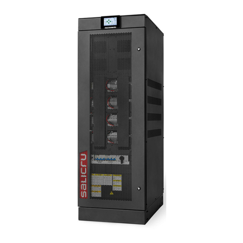
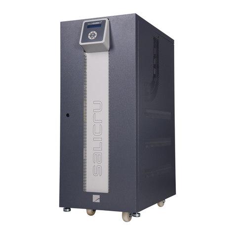
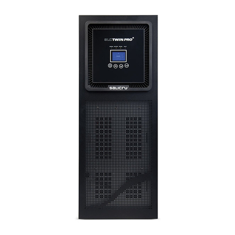
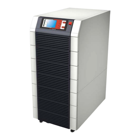
This user manual is intended for units from the SLC CUBE4 series,
of between 7.5 and 20 kVA and consisting of cabinets measuring
(depth x width x height) 688.5 x 250 (370 (1)) x 826.5 mm.
(1) Dimensions corresponding to the unit with the stabilising
supports installed. For safety purposes, it is recommended
to install them to give the unit greater stability, largely avoiding the
risk of tipping (see ).
The following terms are used interchangeably in the document
to refer to:
•"SLC CUBE4, CUBE4, UPS, system, equipment or
unit".- Uninterruptible power supply, CUBE4 series.
Depending on the context of the sentence, they may refer
interchangeably to the UPS itself or to the UPS and the bat-
teries, regardless of whether it is assembled in the same
metal enclosure -box- or not.
•"Batteries or capacitor banks".- A group or set of ele-
ments that stores the flow of electrons by electrochemical
means.
•"T.S.S.".- Technical Service and Support.
•"Customer, installer, operator or user".- They are used
interchangeably and, by extension, to refer to the installer
and/or the operator who will carry out the corresponding
actions, whereby the responsibility for carrying out the
respective actions may be held by the same person when
they act on behalf or in representation of the installer or
operator.
2.1.1. Conventions and symbols
Some symbols may be used and may appear on the unit, bat-
teries and/or in the user manual.
For more information, see section 1.1.1 of document EK266*08
relating to the "Safety Instructions".
When there are differences in relation to the safety instructions
between document EK266*08 and the unit's user manual, those
from the latter will always prevail.
2.1.2. Safety considerations
•Although chapter will cover safety-related considerations
in more detail, the following will be taken into account:
Inside the battery cabinet there are accessible parts
with DANGEROUS VOLTAGES and consequently with a
risk of electric shock, which is why it is classified as a
RESTRICTED ACCESS AREA. Therefore the key for the
battery cabinet will not be available to the OPERATOR
or USER, unless they have been properly instructed.
In the event of an intervention inside the battery cab-
inet, either during the connection, preventive mainte-
nance or repair procedure, it must be taken into account
that the battery group voltage exceeds 200 V DC
and therefore the relevant safety measures must be
taken.
Any connection and disconnection operation of the ca-
bles or handling inside the cabinet must not be carried
out until 10 minutes have passed, in order to allow the
internal discharge of the unit's capacitors. Even so, use
a multimeter to check that the terminal voltage is less
than 36 V.
In case of installing the equipment in IT neutral regime,
the switches, circuit breakers and thermal-magnetic
protection devices must break the NEUTRAL, as well
as the three phases.
