Alpha Outback Energy Continuity 6K User manual

Table of Contents
Page 1 to 45
1. Safety Instructions and Battery Care ............................................................................ 2
1.1. Safety Instructions ----------------------------------------------------------------- 2
1.2. Battery Care ------------------------------------------------------------------------ 5
2. Product Introduction .................................................................................................... 6
2.1. General Characteristics ----------------------------------------------------------- 6
2.2. Symbols on the LCD Display Panel -------------------------------------------- 9
2.3. Panel Explanation --------------------------------------------------------------- 12
2.4. Communication Port ------------------------------------------------------------- 15
3. Installation and Operation .......................................................................................... 16
3.1. Unpacking ------------------------------------------------------------------------ 16
3.2. Selecting Installation Position ------------------------------------------------- 17
3.3. Installation of Accessories Kit ------------------------------------------------ 18
3.4. Terminal Block Explanation --------------------------------------------------- 19
3.5. Installation and Operation ------------------------------------------------------ 23
4.
Troubleshooting Guide............................................................................................... 36
4.1. Troubleshooting ----------------------------------------------------------------- 36
5.
Communication Software ........................................................................................... 38
5.1. Hardware Setup ------------------------------------------------------------------ 38
5.2. Software Installation ------------------------------------------------------------- 38
6.
Optional Interface Cards ............................................................................................ 39
6.1. DCE (Dry Contact)-B card ----------------------------------------------------- 39
6.2. DCE (Dry Contact)-C card ----------------------------------------------------- 40
6.3. Card Installation ----------------------------------------------------------------- 41
7.
Specifications ............................................................................................................. 42

1. Safety Instructions and Battery Care
1.1. Safety Instructions
1.1.1. Because of small leakage currents generated by the EMI filter in the UPS
it is necessary to double check that the ground wire of the UPS is properly
grounded before connecting the UPS to the AC mains.
1.1.2. To ensure safety in all applications where a UPS is hard wired to the
electrical supply, ensure that the system is installed by a qualified electrical
contractor.
1.1.3. The UPS has its own internal energy source (battery). Should the battery
be switched on when no AC power is available there could be voltage at
the output terminals.
1.1.4. Make sure that the AC utility outlet is correctly grounded.
1.1.5. Do not open the case as there are no serviceable parts inside. Opening
the case voids the warranty.
1.1.6. Do not try to repair the unit yourself; contact your local supplier. Repairing
the unit yourself voids the warranty.
1.1.7. Please make sure that the input voltage of the UPS matches the supply
voltage.
1.1.8. Use a certified input power cable with the correct plugs and sockets for the
appropriate system voltage.
1.1.9. To prevent any overheating of the UPS keep all ventilation openings free
from obstruction, and do not store things on top of the UPS. Keep the UPS
30 cm away from the wall.
1.1.10. Ensure that the UPS is installed within the proper environmental range. (0-
40°C and 0-90% non-condensing humidity)
1.1.11. Do not install the UPS in direct sunlight. Your warranty may be void if the
batteries fail.
1.1.12. Install the UPS indoors as it is not designed for installation outdoors.
1.1.13. Dusty, corrosive and salty environments can damage any UPS.
1.1.14. Install the UPS away from objects that give off excessive heat and areas
that are excessively wet.
1.1.15. If liquids are spilt onto the UPS or foreign objects dropped into the unit the
warranty will be null and void.
1.1.16. The battery will discharge naturally if the system is unused for a long time.
1.1.17. The UPS should be recharged every 2-3 months if unused. If this is not
done then the warranty will be null and void. When installed and being
used the batteries will be automatically recharged and kept in top
condition.
1.1.18. This UPS supports electronic equipment in office, telecommunication,
process-control, medical, and security applications. Non-authorized
technicians are not allowed to install the UPS in the following areas.
a. Medical equipment directly related to human life
b. Elevators, subway systems, or any other equipment related to
human safety.
c. Public systems or critical computer systems.
1.1.19. Do not install the UPS in an environment with sparks, smoke or hazardous
gas.
1.1.20. Make sure the UPS is completely turned off when transporting it. It might
cause electrical shock if the output is not cut completely.
1.1.21. The UPS includes a Maintenance Bypass Switch. Please follow the
procedures strictly when switching on or off the Maintenance Bypass
Switch.
Page 3 to 45
Page 2 to 45

1.1.25. The UPS is intended for installation in a controlled environment.
1.1.26. CAUTION: A disconnect switch must be provided by others for the AC
output circuit. To reduce the risk of fire connect only to a circuit provided
with branch circuit over-current protection for 30 amperes for 6 kVA rating
in accordance with the National Electric Code, ANSI/NFPA 70.
1.1.27. CAUTION: To reduce the risk of fire connect the UPS only to a circuit
provided with branch circuit over-current protection for 40 amperes for 6
kVA rating in accordance with the National Electric Code, ANSI/NFPA 70.
1.1.28. Install the UPS so that it is not likely to be contacted by people.
1.1.29. The maximum ambient operating temperature is 40°C or equivalent.
1.1.30. Units are considered acceptable for use in a maximum ambient 40°C
1.1.31. CAUTION - RISK OF EXPLOSION IF BATTERY IS REPLACED BY AN
INCORRECT TYPE. DISPOSE OF USED BATTERIES ACCORDING TO
THE INSTRUCTIONS.
1.1.32. CAUTION - Do not dispose of batteries in a fire. The batteries may
explode.
1.1.33. CAUTION – Do not open or mutilate batteries. Released electrolyte is
harmful to the skin and eyes. It may be toxic.
1.1.34. CAUTION– A battery can present a risk of electrical shock and high short
circuit current. The following precautions should be observed when
working on batteries:
1) Remove watches, rings, or other metal objects.
2) Use tools with insulated handles.
3) Wear rubber gloves and boots.
4) Do not lay tools or metal parts on top of batteries.
5) Disconnect charging source prior to connecting or disconnecting battery
terminals.
6) Determine if battery is inadvertently grounded. If inadvertently grounded,
remove source from ground. Contact with any part of a grounded battery
can result in electrical shock. The likelihood of such shock can be
reduced if such grounds are removed during installation and
maintenance (applicable to equipment and remote battery supplies not
having a grounded supply circuit).
1.1.35. UPS can be used with only one Battery Cabinet
1.2. Battery Care
If the UPS is unused for an extended period of time it must be stored in a
moderate climate. The batteries should be charged for twelve hours every
three months by plugging the UPS power cord into a wall receptacle and
turning on the input breaker on the front panel. Repeat this procedure every
two months under a high-temperature environment.
1.1.22. The UPS offers a CVCF (Constant Voltage Constant Frequency) setting
function.
a. For correct setting and wiring please contact with your local utility
agent.
b. Do not set it yourself or your warranty will be void.
1.1.23. This UPS has been designed and constructed to protect your assets from
the wide range of power aberrations experienced on utility power lines
today. It is your insurance for a reliable, clean and stable voltage supply. It
is worth taking care to install the system correctly and to have it
maintained correctly by your local dealer.
1.1.24. SAVE THESE INSTRUCTIONS. This manual contains important
instructions that should be followed during installation and maintenance of
the UPS and batteries.
Page 5 to 45
Page 4 to 45

2. Product Introduction
2.1. General Characteristics
2.1.1. True online architecture continuously supplies your critical device with
stable, regulated, transient-free, pure-sine-wave AC power.
2.1.2. 20 kHz PWM sine-wave topology yields excellent overall performance. The
high crest factor of the inverter handles all high-inrush current loads
without a need to upgrade the power rating.
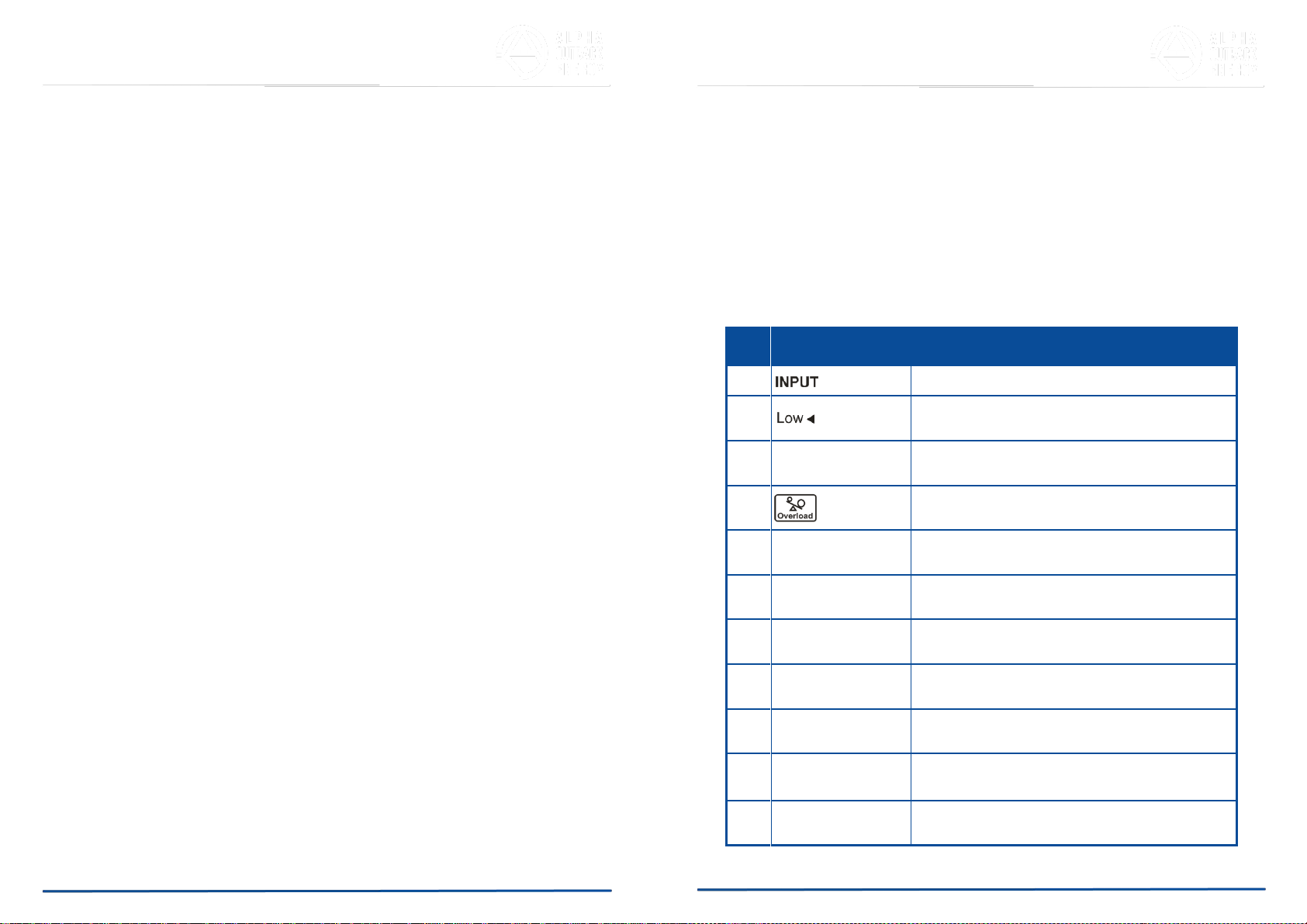
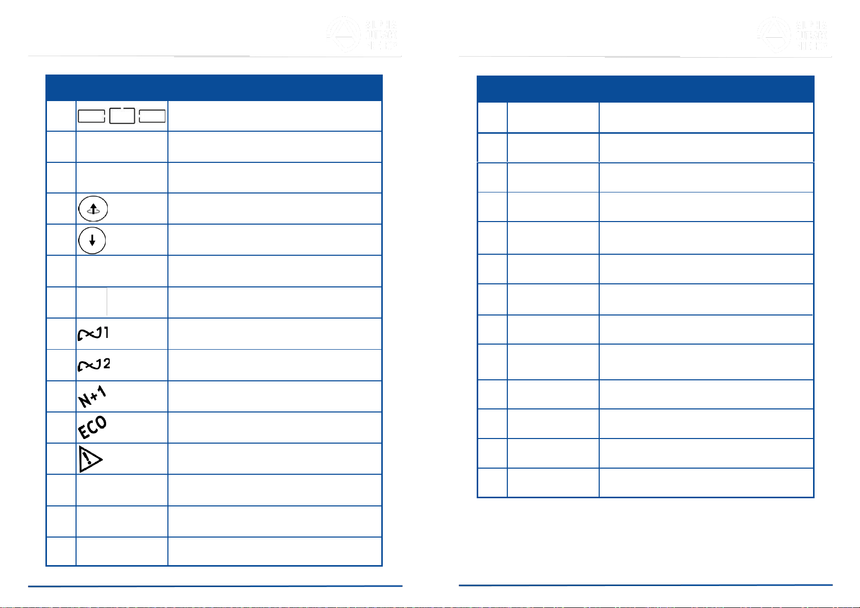
2.1.3. The multi-functional LCD/LED panel displays various states of the UPS.
The LED display shows the UPS working status, utility status and
abnormal status. The LCD display shows input/output voltage, frequency,
load status, inner cabinet temperature, and abnormal phenomena.
2.1.4. To protect the unit from overloading, it automatically switches to bypass
mode in 600 ~ 30 seconds s if loading is at 105 ~125% of rating. In case of
overloading at 125 ~150% of rating, it switches to bypass mode in 30
seconds ~ 160ms. In case of overloading at 150% of rating, it switches to
bypass mode immediately. It will automatically switch back to inverter
mode once the overload condition ceases.
2.1.5. Should the output become short-circuited, the UPS cuts the output
automatically until the short-circuit situation is removed manually.
2.1.6. Should the unit become overheated, the internal thermal switch will detect
the heat and switch to bypass mode and vice versa.
2.1.7. The fully digitalized control circuit built into the UPS allows upgrading the
functionality of the UPS as well as reaching a high-level of protection of the
UPS. Powerful communication capability enhances its ability for remote
control and monitoring.
2.1.10. Providing four different working modes (Normal, ECO, CF50 and CF60) it
may be used in a wide variety of applications.
2.1.11. The DC-start function ensures the start-up of the UPS during power
outages.
2.1.12. A revolutionary battery management circuit analyzes battery discharging
status to adjust the battery cut-off point and extend battery life.
2.1.13. The intelligent, temperature-controlled fan may not only extend the life of
the fan but also reduce annoying noise because of sudden fan spin. This
helps keep your office quiet and comfortable.
2.1.14. When the UPS is out of order you can read the possible reason from the
LCD screen directly, which reduces unnecessary repairs.
2.1.15. When the UPS is operated in CF50 or CF60 mode, the recommended
load connected shall be 75% of rated capacity if the input voltage is 176-
280 VAC and 50% of rated capacity if the input voltage is 160-176 VAC
and 25% of rated capacity if the input voltage is 110-160Vac.
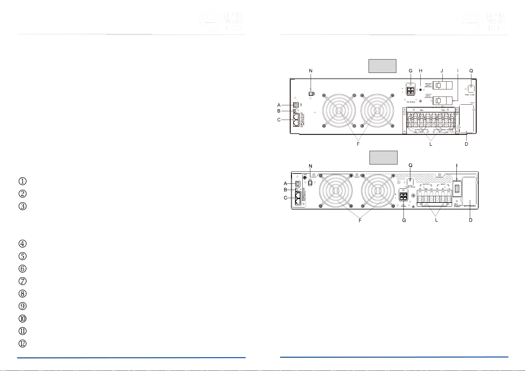
2.1.16. Single input System Block
2.1.8. Maintenance-free, sealed batteries minimize after-sales service.
2.1.9. The maintenance bypass switch provides an easy and safe
troubleshooting or maintenance function when the utility is normal.
Page 7 to 45
Page 6 to 45

2.1.17. Dual input System Block
a. UPS Utility Input: to provide the AC source to the UPS rectifier circuit and charger.
b. UPS Bypass Input: to provide the AC source to the UPS Bypass Input and
Maintenance Bypass loop.
c. UPS Utility Input Breaker: to protect the UPS Rectifier circuit from over-current.
d. UPS Bypass Input Breaker: to protect the UPS Bypass circuit from over-current.
e. EMI Filter on UPS Utility Input: to eliminate the magnetic interference from AC Source
or UPS Utility Input.
f. EMI Filter on UPS Bypass Input: to eliminate the magnetic interference from AC
Source or UPS Bypass Input.
g. Fuse for UPS Utility Input: to provide over-current protection for UPS Rectifier Circuit.
h. Rectifier and Booster: When Utility is normal, they will converts the AC to DC and
correct input power factor. When Utility is abnormal, the batteries will be boosted to
provide the DC voltage to the Inverter.
i. Input fuse for Battery: to protect batteries when DC-Booster is out of order.
j. Charger: the battery charging device.
k. Internal Battery: When AC abnormal, it provide the backup power from the batteries.
l. External Battery Bank: To provide longer backup time by adding additional Battery
bank.
m. Inverter Generator: To convert the DC voltage to AC voltage
n. UPS Inverter Output Fuse: When the UPS is overloaded, the fuse will be opened.
o. Inverter Output Switch: When the UPS is overloaded or abnormal, or the UPS is
working on ECO mode or if EPO (Emergency Power Off) is activated, the Switch will
be opened.
p. Auto Bypass Loop: When the UPS is overloaded or abnormal, the UPS will switch the
UPS to bypass output automatically from inverter output.
q. UPS Output EMI Filter: To eliminate the magnetic interference from the UPS Output
and avoid the interference caused by the output load and the UPS.
2.2. Symbols on the LCD Display Panel
Page 9 to 45
Page 8 to 45
Item Symbol Description
1 Utility or Bypass Source
2 Battery Low
3 Battery Abnormal
4 UPS Overloading
5 UPS Working in specified mode*
6 Bypass Input Abnormal, UPS fails to transfer
to bypass, Bypass Abnormal at ECO mode
7 Utility Input Abnormal
8 OFF UPS Shutoff
9 INPUT OFF UPS Abnormal Lock
10 UPS Flow Chart
11 3-Digit Measurement Display

*The specified modes include Normal mode, ECO mode, CVCF mode, etc..
Page 11 to 45
Page 10 to 45
12 Indicates the item to be measured
13 UPS ON Switch or Alarm Silence
14 UPS OFF Switch
15 Previous Page or Setting Change
16 Next Page
17 Special Function Log In/Out
18 Enter or Reconfirm
19 Utility Input Normal LED
20 Bypass Input Normal LED
21 UPS under Redundancy Mode
22 UPS under ECO Mode
23 UPS Fault or Abnormal Warning LED
24 EPO Emergency Power Off
25 Er05 Battery Weak or Dead
26 Er06 Output Short Circuit
27 Er10 Inverter Over-current
Item Symbol Description
28 Er11 The UPS is overheated.
29 Er12 UPS Output Overloading
30 Er14 Fan Error
31 Er15 Wrong Procedure to Enter Maintenance
Mode
32 Er16 Output Parameters Set Error in Parallel
System
33 Er17 ID Numbers are in conflict in Parallel
System or ID number error in single unit
34 Er21 Parallel communication error (communication wire
disconnected or failure to find ID1 UPS) in Parallel
System
35 Er24 CVCF mode with Bypass input
36 Er27 The UPS must be operated in normal mode
in Parallel System.
37 Er28 Bypass Overload Time out and cut off output
39 Er33 Isolated transformer is overheated.
40 Er** Other Error code
Item Symbol Description

2.3. Panel Explanation
2.3.1. Front Panel
LCD Information
Green LED indicates that the UPS is able to run under redundancy mode.
Solid green LED indicates that the utility input voltage is within the window.
Flashing green LED indicates that the utility input voltage is outside the
acceptable window.
Green LED indicates that Bypass Input is normal.
UPS ON/Alarm Silence
Go to previous page or change the setting of the UPS.
Confirm a changed setting.
Go to the next page.
UPS OFF Switch
Special functions log in/out
UPS is working under ECO (Economical) mode.
UPS Fault or Abnormal
2.3.2. Rear Panel
Con plus
10K 3U
Con plus 6K
2U
Page 13 to 45
Page 12 to 45

A USB Port
B Terminal Resistor for Parallel function
C CAN Bus Connection Port for Parallel System
(Do not for telecommunication network)
D Customer Options Slot 1
F Cooling Fan
G External Battery Connector
H External Battery Ground
I Utility Input Breaker CB1
J Bypass Input Breaker CB2
L Input/output Terminal Block
N EPO-Emergency Power Off-: 2 types switch state, Normal Close
and Normal Open
EPO can be converted to ROO (Remote ON/OFF)
ROO with2 types switch state -Normal Close and Normal Open
ROO and EPO need to use the software switching
Q Temp. Comp.
2.4. Communication Port
2.4.1. The communication port on the UPS provides for USB communication with
the UPS software to remotely monitor the power and UPS status.
2.4.1.1. You may use optional interfaces cards for R2E (RS-232), RSE (RS-485),
USE (second USB), DCE (Dry Contact), and SNMP. However, the R2E
card, RSE card and USE card must not be used simultaneously.
2.4.1.2. The software bundled with the UPS is compatible with many operating
systems such as Windows 2000, XP, Server 2003, VISTA, Server 2008,
Win7 and Win8. For other applications such as Novell NetWare, Unix, or
Linux please contact your local distributor for a proper solution.
2.4.1.3. When the optional interface cards are used together with the onboard
USB port the EPO signals will get highest priority, then the SNMP/WEB
card, then the shutdown command at the DCE, R2E, RSE, and USE
cards, and then finally the onboard USB port gets the lowest priority.
2.4.2. USB Definition:
2.4.2.1. complies with USB version 1.0,1.5 Mbps
2.4.2.2. complies with USB HID version 1.0
2.4.2.3. Pin Assignments:
1 VCC (+5V)
2 D-
3 D-
4 Ground
Page 15 to 45
Page 14 to 45

3. Installation and Operation
Carefully inspect the UPS for shipping damage before installation. Retain the
packing material for future use.
3.1. Unpacking
3.1.1. Standard package contents:
Quick Start Manual
User Manual
Communication software with USB cable
Metal Accessories Kit for RT model as below:
-The tower stand (A1) and the mounting ear (B1 and B2) are for tower and rack
mount installation separately but not for moving UPS.
3.2. Selecting Installation Position
Install the UPS in a proper environment to
minimize the possibility of damage to the UPS and
to extend the life of the UPS. Please follow these
rules:
1. Keep at least 30 cm (12 inches) clearance
from the rear panel of the UPS to the wall.
2. Do not block the air flow to the ventilation
openings of the unit.
3. Ensure that the installation site is not
excessively hot or moist.
4. Do not place the UPS in an environment near
dust, corrosive or salty material, or flammable
objects.
5. Do not expose the UPS to the outdoors.
Page 17 to 45
Page 16 to 45

3.4. Terminal Block Explanation
L12-N1: the terminal for Utility Input to provide the power source when the UPS
is working under Utility mode
G1: the terminal for UPS Input Ground
L21, N22: the terminals for UPS
Output G2: the terminal for UPS Output
Ground
Remarks:
1. The maximum current for each terminal is 36 Arms for 6 kVA, 65 Arms for 10
kVA.
2. If the UPS is a SIM (Single Input) type, only AC source can be supplied to the
UPS from the L12-N1 terminal for the 1-phase.
*Use mounting cable ties to fix cables.
6k model
3.3. Installation of Accessories Kit
Page 19 to 45
Page 18 to 45

Wiring of UPS module, Transformer module
※When Transformer module is combined with UPS, connect
the utility to Transformer module first, share the utility to
UPS from Transformer module socket.
3. Please refer to the specifications of input current, output current and
recommended conductors listed below.
a. AC input and output (minimum 75°C copper wire)
b. Battery input
Page 21 to 45
Page 20 to 45
Model Maximum Current Conductor Section
6KVA(Tower/RT) 36 A
AWG
#
10
10KVA 62A/50A
AWG
#
8
Model Maximum Current Conductor Section
6KVA 36 A
AWG
#
10
10KVA 53A
AWG
#
8

Wiring of UPS module and Battery module
3.5. Installation and Operation
3.5.1. Start Up in Normal Mode
3.5.1.1. Open the terminal block cover on the rear panel. (Refer to 2.3.2.) Before
starting the installation make sure the grounding is connected properly.
3.5.1.2. Make sure the utility breaker and the UPS’ Utility breaker and Bypass
breaker are in the “Off” position.
3.5.1.3. Make sure the utility voltage matches the input voltage window of the
UPS.
3.5.1.4. Connect the utility separately to the terminal blocks of the UPS’ Utility
and Bypass inputs. Switch on the power breaker of the distribution panel
and the breakers of the UPS’ Utility and Bypass inputs. Then the UPS
will start up. Green LEDs and show that the Utility and Bypass
inputs are normal. UPSs with parallel function enabled will display first
figure A1, then figure A2, and then figure B. Otherwise the LCD will
display figure A1 directly followed by figure B.
A1.
A2.
B.
Page 23 to 45
Page 22 to 45

Page 25 to 45
Page 24 to 45
3.5.1.5. The UPS is in Bypass Mode now. It will proceed to self-test
automatically. If no abnormal message appears then the pre-startup of
the UPS was successful and the charger starts to charge the batteries.
3.5.1.6. Press the UPS On Switch for approximately three seconds. The
Buzzer sounds twice and the LCD display changes from figure B to
figure C.
C
3.5.1.7. The UPS is in self-test mode again. The LCD display will change from
figure C to figure D, and the UPS will remain in battery mode for
approximately four seconds. Then the display will change from figure E1
to figure F if the self-test was successful.
D
“test”
E1
“OK” in self-test
E2
“Fail” in self-test
F
“220 VAC” in Utility Input
3.5.1.8. If the self-test fails the LCD display will change from figure D to figure
E2. Then an error code or error status will appear on the screen.
3.5.1.9. Your start-up operation of the UPS is complete now. Make sure the UPS
is plugged into the wall receptacle for charging at least 8 hours and the
batteries are fully charged before connecting the device to be protected.
3.5.2. Start-up in Battery Mode (Cold Start)
3.5.2.1. Make sure the UPS has at least one set (12-16 pcs) of 12V/9AH
batteries.
3.5.2.2. Push the UPS On Switch once for approximately 5 seconds to
awaken the UPS. The buzzer will sound twice. The LCD display will
change from figure A to figure G for approximately 15 seconds.
3.5.2.3. Press the UPS On Switch again for about three seconds until the
LCD display changes from figure G to figure H. Then the UPS will be in
self-test mode. The UPS may offer energy to the output in a minute, and
the LCD displays figure I. In case of failure in pushing the UPS On
Switch for 15 seconds, the UPS will automatically turn off. You must then
repeat steps 3.5.2.1 to 3.5.2.3.
G
“Off”, which means the UPS pre-start was successful

H
Utility input is “0” and Utility Abnormal.
Page 27 to 45
Page 26 to 45
I
3.5.3. Check Measured Values and Figures detected by the UPS
3.5.3.1. If you would like to check the measured values and figures detected by
the UPS use the scroll up and scroll down keys. When you
scroll down the LCD will display figure C (Voltage from Utility Input)
figure I1 (Voltage from Bypass Input) figure J (Frequency from Utility
Input) figure K (Frequency from Bypass Input) figure L (UPS
Output Voltage) figure M (UPS Output Frequency) figure N (UPS
Output Load %) figure O1 (UPS Battery Voltage)O2 (UPS Battery
Numbers) figure P (UPS Inner Temperature).
I1
Voltage comes from Bypass Input.
J
frequency of Utility Input
K
frequency of Bypass Input
L
UPS output voltage
M
UPS output frequency

N
UPS output load level (%)
O1
UPS battery voltage
O2
UPS battery numbers
Page 29 to 45
Page 28 to 45
P
UPS inner temperature
3.5.4. UPS Default Data and Special Function Execution
3.5.4.1. After the UPS completely starts up, press the key to change the
LCD display to figure Q1.
Q1
buzzer “On”
Q2
buzzer “Off”

3.5.4.2. Press the key to scroll through the UPS settings. The LCD will
display in sequence figure Q1 (buzzer) figure R1 (Self-test) figure
S1 (Bypass Voltage Windows) figure T (Output Frequency
Synchronization Window) figure U (Inverter Output Voltage) figure
V1 (UPS Operation Mode) figure W (Output Voltage Micro Tune
Value) figure X (UPS Id) figure Y (Parallel function status).
R1
Self-test is not “On”.
R2
Self-test is “On”.
S1
Bypass Voltage is adjusted to wide range.
S2
Bypass Voltage is adjusted to narrow range.
Page 31 to 45
Page 30 to 45
T
Frequency Window is +/-3 Hz.
U
inverter output voltage
V1
The UPS is operating in “normal mode”.
V2
The UPS is operating in “Eco mode”.

Y
The parallel function is disabled.
3.5.4.3. Press the scroll up key to execute special functions. The functions
include buzzer ON (as in figure Q1), buzzer OFF (as in figure Q2, Alarm
silence for UPS Warning), and self-test OFF (as in figure R1) or self-test
ON (as in figure R2). The UPS will execute the battery test for ten
seconds. If the self-test is successful it will display figure E1; otherwise, it
will display figure E2 and an error message at the same time.)
V3
Page 33 to 45
Page 32 to 45
3.5.5. UPS Default Settings and their alternatives
3.5.5.1. Make sure the UPS is not “On”. Press the On and scroll down
keys simultaneously for approximately three seconds. The buzzer will
sound twice, and the LCD will display figure Q1, indicating that the UPS
is in setting mode.
3.5.5.2. To scroll through the options refer to section 3.5.4.2.
3.5.5.3. Except for Buzzer (figures Q1 and Q2) and Self-test (figures R1 and R2)
all of the other default settings may be changed by pressing the scroll up
key.
3.5.5.4. Figures S1 and S2 indicate the bypass input acceptable window. It
follows the inverter output voltage. Please refer specification for the
detail.
3.5.5.5. Figure T indicates the bypass frequency window of the Inverter Output.
The acceptable setting values are ±3 Hz and ±1 Hz.
3.5.5.6. Figure U indicates the acceptable Inverter Output Voltage. Possible
values are 200, 208, 220, 230, or 240 VAC.
3.5.5.7. Figures V1, V2, V3 and V4 indicate the operation modes of the UPS.
Possible values are Online, Eco (Economical) mode, fixed 50 Hz
Output, and fixed 60 Hz Output.
The UPS is operating in “CVCF 50 Hz mode”.
V4
The UPS is operating in “CVCF 60 Hz mode”.
W
Output Voltage Adjustment (-3%, -2%, -1%, 0%, +1%, +2%, +3%)
X
UPS position in parallel mode

3.5.5.11. After changing settings you must scroll to the “End” screen (figure Z) and
then press the enter key to save all of your changes. Then the LCD
will display figure AA to indicate completion of the setting changes. To
cancel your changes rather than save them press and hold the “OFF”
key for five seconds. The LCD displays figure AA directly, which
indicates that your changes were canceled.
Z
* Press the Enter key to save changes.
AA
The UPS is locked.
3.5.5.12. Turn Off the Utility Input breaker.
3.5.5.13. Your setting changes are now complete.
3.5.6. Troubleshooting when the UPS is Off Due to Unknown Reasons
3.5.6.1. If there is a serious abnormal condition the UPS will lock itself in the
“OFF” position as shown in figure AA, and an “abnormal” message will
appear on the LCD.
3.5.6.1.1. After three seconds all messages will be locked except both Bypass
messages (LED and LCD ) and Utility messages (LED
and LCD ). If the Bypass or Utility is abnormal after the
UPS is locked, the related LED or will be extinguished
and also the related LCD symbol or will appear.
3.5.6.2. To release the UPS lock proceed as follows:
3.5.6.2.1. Check the recorded error messages.
3.5.6.2.2. Check the error messages in section 2.2 to help troubleshoot the
problem. For further help consult your local distributor.
3.5.6.2.3. Press the Off key for five seconds. A buzzer will sound twice.
3.5.6.2.4. Turn Off the Utility Input breaker.
3.5.6.2.5. Even if the UPS lock problem is solved now, consult with your local
distributor to make sure that the error condition is resolved.
3.5.7. Shut Off
3.5.7.1. Press the Off key for five seconds. The Inverter output will be turned
off, and the output load will be supplied by the Bypass loop. The LCD will
display figure B.
3.5.7.2. Turn Off the Utility and Bypass Input breakers.
3.5.7.3. The UPS is now turned off completely.
Page 35 to 45
Page 34 to 45
3.5.5.8. Figure W indicates the adjustment of the Inverter Output, which may be
set to 0%, +1%, -1%, +2%, -2%, +3%, or -3%.
3.5.5.9. Figure X indicates the position of the UPS when the UPS is in Parallel
mode. Possible positions are 1, 2, 3, and 4. The position must be 1 if the
UPS is not in Parallel mode.
3.5.5.10. Figure Y indicates the parallel function status. “P 01” indicates that the
parallel function is disabled, and “P 02” indicates that the parallel
function is enabled.
3.5.8. Maintenance Bypass Mode
3.5.8.1. Maintenance Bypass Mode is for UPS maintenance only. Only
authorized technicians are allowed to perform the following procedures.
If there is any damage during unauthorized execution of these
procedures your warranty will be void immediately.
3.5.8.1.1. Press the Off key for approximately five seconds. The LCD will
display figure B, and the UPS output will be in bypass mode.
3.5.8.1.2. Remove the cover of the CAM Switch (Maintenance Bypass Switch),
then turn on the CAM Switch to “Bypass” mode. In the upper right-
hand corner of the LCD a sign will appear.

3.5.8.1.3. Turn off the UPS Utility breaker as well as the Bypass Input Breaker.
You may proceed with UPS maintenance now.
3.5.8.1.4. When you are done with UPS maintenance put the UPS back into
normal working mode as explained in section 3.5.1.4. Then return the
CAM switch to “INV” mode, replace the cover, and repeat sections
3.5.1.5 to 3.5.1.8. The UPS will switch back to inverter mode.
3.5.8.1.5. You must perform section 3.5.8.1.1 before section 3.5.8.1.2. If you skip
section 3.5.8.1.1 the UPS will alert for ten seconds to warn that the
procedure is abnormal and may damage the UPS due to uncertain
utility status. The UPS will switch back to Inverter mode immediately if
you turn the CAM switch back to “INV”.
4. Troubleshooting Guide
4.1. Troubleshooting
If the UPS malfunctions during operation first check the following:
a. Is the input and output wiring correct?
b. Is the input voltage of the utility within the input window of the UPS?
If problems still exist check the following for proper adjustment. Should the
problem still persist, please contact your local distributor for help.
Page 37 to 45
Page 36 to 45
Situation Check Items Solution
red Fault LED Check the error code
shown on the LCD.
1.
Check for proper battery
connection, then recharge the
batteries for 8 hours to see
whether the UPS provides
backup power normally;
otherwise, consult your local
distributor right away.
2.
If CB3 is tripped, turn off the
UPS completely and keep the
CAM switch at position INV before
pressing CB3. Then remove some
uncritical load at the UPS output
end. If there is any damage to the
insulation of the AC power cord,
please replace it with a new one.
3.
Remove the short circuit at the
EPO terminal.
4.
Remove any objects
blocking the ventilation holes.
5.
Check that the cooling fans on
the rear panel are working normally.
6.
Make sure the UPS is
operated normally. If it is in CVCF
mode you must turn off and turn
on the UPS again.
7.
All of the parameters except ID
Number in a parallel UPS must be
the same. Please refer to section
3.5.5 to set them again.
8.
Disconnect and reconnect the
RJ45 connector or set a UPS
with ID=1.
9.
When the UPS is in CVCF
mode it is prohibited from having
bypass input. You must turn off the
UPS and bypass input and then
restart the UPS.
10.
Consult your local distributor for help.
1.Er05, &
2.Er06, Er10, Er12, Er28
3.EPO
4.Er11, Er33
5.
Er14
6.
Er15
7.Er16, Er17, Er27
8.
Er21
9.
Er24
10.
other error code
This manual suits for next models
1
Table of contents
Other Alpha Outback Energy UPS manuals

Alpha Outback Energy
Alpha Outback Energy CableUPS XM3V-HP User manual

Alpha Outback Energy
Alpha Outback Energy Tetrex 500 User manual

Alpha Outback Energy
Alpha Outback Energy Alpha FXM 650 User manual

Alpha Outback Energy
Alpha Outback Energy Tri Power X33 HE User manual

Alpha Outback Energy
Alpha Outback Energy Continuity 1000 User manual

Alpha Outback Energy
Alpha Outback Energy Sentra XL User manual

Alpha Outback Energy
Alpha Outback Energy Tri Power X33 SE Series User manual

Alpha Outback Energy
Alpha Outback Energy FXM 350 Series User manual