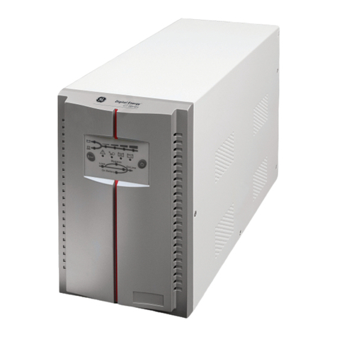
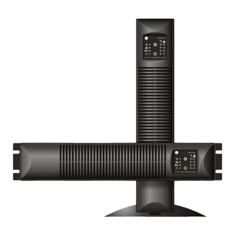
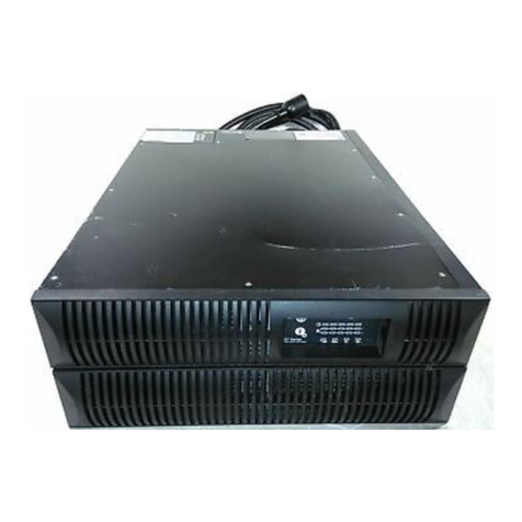
GE EP 700T User manual


--
1. SAFETYINSTRUCTIONS
1.1Installation
★CondensationmayoccuriftheUPS ismoved directlyfromacoldtoawarm
environment. The UPS mustbe absolutelydrybeforebeing installed.Please
allowan acclimatization timeof at least twohours.
★Donot install the UPS nearwaterorindampenvironment.
★Donot install the UPS whereit wouldbe exposed todirect sunlight ornearheat.
★Donot block ventilation openingsinthe UPSshousing.
★Donotconnectappliancesoritemsofequipmentwhichwouldoverload the UPS
(e.g. laserprinters, etc)tothe UPS outlet sockets.
★Placecablesinsuchawaythat no one can step on ortripoverthem.
InstallationforEP700/1000/2000/3000
★Socket-outletsand socketofbatteriesareearthed bytheinput powercord,please
insert the powercordintomainssocket beforeusing of UPS.
★Connect the UPS onlytoan earthed shockproof socket outlet.
★The building wiringsocketoutlet(shockproofsocketoutlet)mustbe easily
accessibletoclosetothe UPS.
★Thisisoperatorinstallable.
InstallationforEP6000
★UPS hasprovided earthed terminal,inthefinalinstalledsystemconfiguration,
equipotentialearthbonding tothe externalUPS batterycabinets.
★Anintegralsingleemergency switching devicewhichpreventsfurthersupplytothe
load bythe UPS inanymode of operation shouldbeprovidedinthe building wiring
installation.
★Anappropriatedisconnectdeviceasshort-circuitbackupprotectionshouldbe
provided inthe building wiring installation.
★Forthree-phaseequipmentconnection toan ITpowersystem,afour-poledevice
whichdisconnectallphaseconductorsandthe neutralconductorshouldbe
provided inthe building installation wiring.
★Thisispermanentlyconnectedequipment,itmustbe installed byqualified
Pleaseread the FOLLOWING user manualand the safetyinstructions
before installing the unit and starting it up!

-2-
maintenancepersonnel.
★Earthconnection essentialbeforeconnecting tothe building wiring terminal.
1.2Operation
★DonotdisconnectthemainscableontheUPS orthe buildingwiring socket
(grounded shockproofsocket)during operationasthiswouldremovethe ground to
the UPS and of all connected loads.
★The UPS outputsocketoroutputterminalblockmaybe electricallylived even ifthe
UPS systemisnot connected tothe building wiring terminal.
★Inordertofullydisconnect theUPS,firstpressthe Standbybutton, thendisconnect
the mainslead.
★Ensurethat no liquidorotherforeign objectscan enterthe UPS.
★The UPS can be operated byanyindividualswithno previousexperience.
1.3Maintenance, servicing and faults
★The UPS operateswithhazardousvoltages.Repairsmaybe carried outonlyby
qualified maintenancepersonnel.
★Caution-risk ofelectricshock.Even aftertheunit isdisconnected fromthe mains
powersupply(buildingwiring socket),componentsinside the UPS arestill
connected tothe batterywhicharepotentiallydangerous.
★Beforecarryingoutanykind ofserviceand/ormaintenance,disconnectthe
batteries.Verifythatnocurrentispresentandnohazardousvoltageexistsinthe
capacitororBUScapacitorterminals.
★Batteriesmust be replaced onlybyqualified personnel.
★Caution-risk ofelectricshock.The batterycircuitisnotisolated fromthe input
voltage.Hazardousvoltagesmayoccurbetween the batteryterminalsandthe
ground. Verifythat no voltage ispresent beforeservicing!
★Batterieshaveahigh short-circuitcurrentand posearisk ofshock.Takeall
precautionarymeasuresspecifiedbelowand anyothermeasuresnecessarywhen
working withbatteries:
removeall jewellery, wristwatches, ringsand othermetalobjects
useonlytoolswithinsulated gripsand handles.
★Whenchangingbatteries,replacewiththesamequantityandthe sametype of
batteries.
-3-
★Donot attempt todisposeof batteriesbyburning them. It couldcauseexplosion.
★Donotopen ordestroybatteries.effluentelectrolytecan causeinjurytothe skin
and eyes. It maybe toxic.
★Pleasereplacethefuseonlybyafuseof thesametype and ofthe sameamperage
inordertoavoidfirehazards.
★Donot dismantlethe UPS, except the qualified maintenancepersonnel.
1.4Transport
★Pleasetransportthe UPS onlyinthe originalpackaging (toprotectagainstshock
and impact).
1.5Storage
★The UPS must be stockpiled inthe roomwhereit isventilated and dry.

-4-
2. DESCRIPTIONOF COMMONLYUSEDNOTATIONS
Someorallofthe following Notationsmaybeusedinthismanualandmayappearin
yourapplicationprocess.Therefore,all usersshouldbe familiarwiththemand
understand theirexplanations.
NotationandExplanation
Notation Explanation Notation Explanation
Alert you topayspecialattention Protectiveground
Caution ofhighvoltage Alarmsilence
Turnon the UPS Overload indication
Turnoffthe UPS Battery
Idleorshut downthe UPS Recycle
Alternatingcurrent source(AC)
Donot disposewithordinary
trash
Direct current source Refertomanual

-5-
3. INTRODUCTION EP700/1000/2000/3000/6000
ThisOn-Line-Seriesisan uninterruptiblepowersupplyincorporating double-converter
technology. It providesperfect protection specificallyforNovell, WindowsNTand
UNIXservers.
The double-converterprincipleeliminatesall mainspowerdisturbances. Arectifier
convertsthe alternating current fromthe socket outlet todirect current. Thisdirect
currentchargesthebatteriesand powerstheinverter. OnthebasisofthisDC voltage,
the invertergeneratesasinusoidalACvoltage,whichpermanentlysuppliesthe loads.
Load likecomputersand peripheryarethuspowered entirelybythe mainsvoltage. In
the event of powerfailure, the maintenance-free batteriespowerthe inverter.
Thismanualcoversthe UPS listed asfollows. Pleaseconfirmwhetherit isthe model
you intend topurchasebyperforming avisualinspection of the ModelNo. on the rear
panelof the UPS.
Model No. Type
EP 700T
EP 1000T
EP 2000T
EP 3000T
EP 6000T
TowerModel
EP 700LRT
EP 1000LRT
EP 2000LRT
EP 3000LRT
EP 6000LRT
TowerModelwithLongbackuptime
EP 700R
EP 1000R
EP 2000R
EP 3000R
EP 6000R
Rack Model

-6-
4. SYSTEMDESCRIPTION EP700/1000/2000/3000/6000
Switch Function
ON-Switch
Turnon UPS system:
Bypressingthe ON-Switch ON the UPS systemisturned on.
Deactivateacousticalarm:
Bypressingthisswitchan acousticalarmcan bedeactivated.
OFF-Switch
When mainspowerisnormaland Bypass isenable,the UPS systemswitchesto
Standbymode bypressingOFF-Switch OFF. It isthen switched toBypass and
the inverterisoff.At thismoment, maybethe output socketsaresupplied with
voltageviathe bypass ifthe mainspowerisavailableand bypass isenable.
When UPS ison batterymode, pressingOFF-Switch OFF will shutdownUPS.
EP700T/700LRT/1000T/1000LRT/2000T/2000LRT
/3000T/3000LRT/6000T/6000LRT
EP700R/1000R/2000R/3000R/6000R

-7-
Display Function
ACINPUTLED
The green ACINPUTLEDlightsupifmainsvoltageisapplied tothe UPS input.
ACINPUTLEDblinks when the phaseand neutralconductorhavebeen
reversed at the input ofthe UPS system.
IfACINPUTLEDand BATTERYLEDlight up, the mainspowersupplyisout of
tolerance.
BATTERYLED The orange-coloured BATTERY-LEDlightsupwhen the mainspowerhasfailed
and the inverterisbeingpowered bythe batteries.
BYPASS LED The orange-coloured BYPASS LEDlightsupwhen the UPS systemissupplying
voltageprovided bythe mainspowerviathe bypass.
UPS ONLED The green-coloured UPS ONLEDlightsupifthe UPS systemissupplying
voltageprovided bythe mainspowerviathe inverter.
ALARMLED The red ALARMLEDlightsupand an acousticwarningsignalisissued
continuouslywhen theUPS systemisinfault condition. Press the OFF switchin
ordertoturnoffthe warningtone.
Display Function
LOADand
BATTERY
CAPACITY
LEDs(#2~#6)
(For
EP700/1000/2000
/3000)
TheseLEDsshowthe load ofthe UPS systemifthe mainspowerisavailable
(normaloperation):
2nd LED: 96%-108%3rdLED: 71%-95%4thLED: 51%-70%
5thLED: 31%-50%6thLED: 0-30%
Inthe batteryoperation, the LEDsindicatethe capacityofthe batteries:
2nd LED: 100%3rdLED: 76%-100%4thLED: 51%-75%
5thLED: 26%-50%6thLED: 0-25%
LOADand
BATTERY
CAPACITY
LEDs(#2~#6)
(ForEP6000)
TheseLEDsshowthe load ofthe UPS systemifthe mainspowerisavailable
(normaloperation):
2nd LED: 96%-105%3rdLED: 76%-95%4thLED: 56%-75%
5thLED: 36%-55%6thLED: 0-35%
Inthe batteryoperation, the LEDsindicatethe capacityofthe batteries:
2nd LED: 81%-100%3rdLED: 61%-80%4thLED: 41%-60%
5thLED: 21%-40%6thLED: 0-20%

-8-
5. CONNECTIONAND OPERATION EP700/1000/2000/3000
5.1Inspection: Inspectthe packaging carton and itscontentsfordamage.Pleaseinform
the transport agency immediatelyshouldyou find signsof damage.
Pleasekeep the packaging inasafeplaceforfutureuse.
Note: Pleaseensurethattheincomingfeederisisolatedand securedtopreventitfrom
beingswitchedbackonagain.
5.2Connection:
1)UPSInputConnection
If the UPS isconnected viathe powercord, pleaseuseapropersocket with
protection against electriccurrent, and payattention tothe capacityof the socket:
over7AforEP700/1000, over12AforEP2000 and over16AforEP3000.
2)UPSOutputConnection
The output of EP700/1000/2000/3000 aresocket-typesonly. Simplyplug the load
powercordtothe output socketstocompleteconnection.
Model No. OutputSocket(pcs)
EP700 4
EP1000 4
EP2000 6 forTower&4forRack
EP3000 6 forTower&2forRack
3)ComputerConnection:
Connect yourload tothe outlet socketsof the UPS systemdirectly.
5.3BatteryCharge: Fullycharge the batteriesof the UPS systembyleaving the UPS
systemconnected tothe mainsfor1-2hours.You mayusethe UPS systemdirectly
The systemmaybe installed and wired onlybyqualified electriciansin
accordancewithapplicablesafetyregulations!
When installingthe electricalwiring,pleasenotetheratedcurrent
ofyour
incoming feeder
Caution!
Donot connect equipment whichwouldoverload the UPS system(e.g. laser
printers)

-9-
withoutcharging it butthe storedenergytimemaybe shorterthan thenominalvalue
specified.
5.4TurnOntheUPS:
1)Withutilitypowerconnecting:
Press ON button continuouslyformorethan 1second toturnon the UPS.Then the
UPS will getintoself-teststatusfirst. Afterhaving finishing the self-test, the UPS will
get intothe invertermode, at thistime, the ACINPUTLED, InverterLED, and Load
and BatteryCapacityLEDswill light up.
2)Withoututilitypowerconnecting:
Even though utilitypowerisnot connected tothe UPS, the UPS still can be turned
on byjust simplypressing ON button continuouslyformorethan 1second.Then
the UPS will getintoself-teststatusfirst. Afterhaving finishing the self-test, the UPS
will get intothe invertermode, at thistime, BatteryLED, InverterLED, Load and
BatteryCapacityLEDswill light up.
Note: Thedefaultsettingforbypass modeisnooutputafterUPSisconnectingutility
powerand breakeristurnedon.Thiscanbeconfiguredbymonitoringsoftware.
5.5TestFunction:
Test the function of the UPS systembyeitherpressing the Onbutton ordisconnecting
the input of the UPS systemfromthe powersupply.
5.6TurnOff theUPS:
1)InInverterMode:
Press OFF buttoncontinuouslyformorethan 1secondtoturnoff theUPS.Thenthe
UPS willgetintoLEDself-teststatusfirst. Afterhaving finishedthe self-test, theUPS
will get intoStandbymode (orBypass mode if Bypass enable)and the ACINPUT
LED(and Bypass LEDifBypass enable)willlightup.Atthistime,the UPS mighthas
output (if Bypass enable). Disconnect the utilitypowertoturnoff the output.
2)InBatteryMode:
Press OFF buttoncontinuouslyformorethan 1secondtoturnoff theUPS.Thenthe
UPS will get intoself-test statusfirst. Afterhaving finished the self-test, the UPS will
be turned off completely.
5.7AudibleAlarm MuteFunction: If the alarmistoo annoying inbatterymode, you
maypress ON button continuouslyformorethan 1second toclearit. Moreover, the
alarmwill be enabled when the batteryislowtoremind you toshutdownthe load
soon.

-0-
5.8OperationProcedureofExternal Battery
1)Usethe batterypack withvoltage: 36VDC forEP700/1000 (3pcs of12Vbatteries),
96VDC forEP2000/3000 (8pcsof 12Vbatteries).Connectionofbatteriesmorethan
orless than required will causeabnormality
2)One end of the externalbatterycordisaplug forconnecting the UPS and the other
end hasaplug forconnecting the userbatterycabinet
3)(Donot connect the UPS toanyload at thistime). Then, connect the powercordof
the UPS tosupplyutilitypowertothe UPS tomakethe UPS operateinutilitypower
mode.
4)Connect the plug of the externalbatterycordtothe externalbatterysocket on the
rearpaneloftheUPS tocompletetheconnectionprocedureandtheUPS will startto
charge the batterypack.
Caution!
The output socketsof the UPS systemmaystill be electricallyliveeven ifthe power
supplysystemhasbeen disconnected.

--
6. TROUBLESHOOTING-EP700/1000/2000/3000
If the UPS systemdoesnotoperatecorrectly,pleaseattempttosolvethe problemusing
the tablebelow.
Problem Possiblecause Remedy
Noindication, no warningtone even
thoughsystemisconnected to
mainspowersupply Noinput voltage Check buildingwiringsocket
outlet and input cable.
ACINPUTLEDblinks
Phaseand neutral
conductorat input of
UPS systemare
reversed
Rotatemainspowersocket by
180°orconnect UPS system.
ACINPUTLEDblinks and
BATTERY-LEDlightsup
Input powerand/or
frequencyareout of
tolerance
Check input powersourceand
informsellerifnecessary
ACINPUTand BYPASS LEDlight
upeven thoughthe powersupplyis
available Inverternot switched on
Press On-Switch ON
UPS ONLEDlightsup, and audible
alarmsoundingevery1beepin
every4seconds
Mainspowersupplyhas
failed
Switchingtobatterymode
automatically. When audible
alarmsoundingeverysecond,
batterycapacityislow.
ALARMLEDlights, warningtone
onceasecond Overload RemoveloadsfromUPS output.
ALARMLEDlightsup, permanent
warningtone UPS fault Notifyseller!
Emergencysupplyperiod shorter
than nominalvalue
Batteriesnot fully
charged / batteries
defect
Chargethe batteriesforat least
3hoursandthen check capacity.
Ifthe problemstill persists,
consult seller.
ALARMLEDlights, BATTERY-LED
blinks, warningtone onceasecond
ChargerorBatteries
damaged Notifyseller!
Pleasehavethe followinginformation at hand beforecallingthe After-SalesServiceDepartment:
●Modelnumber, serialnumber
●Dateon whichthe problemoccurred
●Detailed description ofthe problem

-2-
7. MAINTENANCE-EP700/1000/2000/3000
7.1Operation
The UPS systemcontainsno user-serviceableparts.If the batteryservicelife(3-5
yearsat 25°Cambient temperature)hasbeen exceeded, the batteriesmust be
replaced. Inthiscasepleasecontact seller.
7.2Storage
If the batteriesarestored intemperate20°C~25°C, theyshouldbecharged everythree
monthsfor1-2hours.You shouldshorten the charging intervalstotwomonthsat
locationssubject tohigh temperatures.

-3-
8.TECHNICALDATA-EP700/1000/2000/3000
8.1Electrical specifications
INPUT
ModelNo. EP700 EP1000 EP2000 EP3000
Phase Single
Frequency (46~54)Hzfor50Hzsystem&(56~64)Hzfor60Hzsystem
Current(A) 7A 7A 12A 16A
OUTPUT
ModelNo. EP700 EP1000 EP2000 EP3000
Powerrating(VA/W)
700/490 1000/700 2000/1400 3000/2100
Voltage 220/230/240VAC 士2%
Frequency 50/60Hz ±0.2%(Batterymode)
Waveform Sine Wave
BATTERIES
ModelNo. EP700 EP1000 EP2000 EP3000
Numberand type 3×12V7.2Ah
3×12V7.2Ah
8×12V7.2Ah
8×12V7.2Ah
8.2Operating Environment
OperatingTemperature 0oCto40oC(20°C~25°Crecommended)
Operatinghumidity <95%
Altitude <1000m
Storagetemperature -15oC~40oC
Note: if1000m<Altitude<3500m(outputderating:1%deratingper100m)
8.3Typical storedenergytime(Typical values at 25°Cinminutes:)
ModelNo. 100 %Load 50 %Load
EP700 5 10
EP1000 5 10
EP2000 5 10
EP3000 5 10

-4-
8.4Dimensionsand weights
Model No. DimensionsWxDxH
(mm) NetWeight
(kg)
EP700T 145X400X220 14
EP700LRT 145X400X220 7
EP700R 482X420X87 15
EP1000T 145X400X220 14
EP1000LRT 145X400X220 7
EP1000R 482X420X87 15
EP2000T 192 X460X340 34.5
EP2000LRT 192 X460X340 15
EP2000R 482X420X87 9.6
EP3000T 192 X460X340 35.5
EP3000LRT 192 X460X340 16
EP3000R 482X420X87 10
Batterypack 96VRack 482X420X87 26

-5-
9. TECHNICALDATA EP6000
9.1General Specification
Model EP6000 EP6000LRT EP6000R Batterypack
(240V)
PowerRating
(VA/W) 6000/4200
Frequency(Hz) 50/60
Voltage (176-276)VAC
Input Current 31Amax.
Voltage 240VDC
Battery Current 24Amax
Voltage 220/230/240VAC
Output Current 27A
Dimension (WxDxH)
mm 260x570x717
260x570x717
482.6X600X130
(3U) 482.6X600X130
(3U)
Net Weight (kg) 90 35 18.3 64.2
9.2Electrical Performance
Input
Model Voltage Frequency PowerFactor
EP6000 Single-phase (46~54)Hzfor50Hzsystem
(56~64)Hzfor60Hzsystem >0.98 (Full load)
Output
Voltage
Regulation
Power
Factor
Frequency
tolerance. Distortion Overload capacity Current
crest ratio
±2% 0.7lag
Synchronized
46-54HzinLine
mode (ACmode)
±0.1%ofnormal
frequencyin
Batterymode
THD<3%Full
load (Linear
Load)
105%-
130%load transfers
tobypass mode after10
seconds
>130%load transfersto
bypass mode after1
second and shutdownthe
output after1minute
3:1
maximum

-6-
9.3Operating Environment
Temperature Humidity Altitude Storagetemperature
0°C~40°C <95% <1000m -15°C~40°C
Note: OutputpowerisderatedwhenUPSisabove1000masfollowing:
Altitude (M) 1000
1500
2000
2500
3000
3500
4000
4500
5000
DeratingPower
100%
95% 91% 86% 82% 78% 74% 70% 67%
This manual suits for next models
14
Table of contents
Languages:
Other GE UPS manuals

GE
GE Digital Energy VH 700 User manual

GE
GE Digital Energy LP 11 User manual

GE
GE SG 300 User manual

GE
GE FGC TLE Series User manual

GE
GE Digital Energy LP 31 Series User manual

GE
GE LP 33U Series User manual

GE
GE Digital Energy LP 11U User manual

GE
GE GT6000 User manual

GE
GE SG 225 User manual

GE
GE Digital Energy LP 33 Series User manual

GE
GE Match User manual

GE
GE GT Series User manual

GE
GE Digital Energy LP 33 Series User manual

GE
GE Digital Energy GT Series User manual

GE
GE LanPro 11 U User manual

GE
GE NetPro Series User manual

GE
GE SG Series User manual

GE
GE Digital Energy LP 33 Series User manual

GE
GE Lanpro 33 User manual

GE
GE Digital Energy LP 11U Instruction Manual