manuals.online logo
Brands
  1. Home
  2. •
  3. Brands
  4. •
  5. Huawei
  6. •
  7. Wireless Access Point
  8. •
  9. Huawei RTN510 User manual

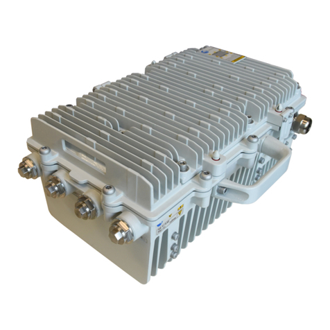
Huawei RTN510 User manual

3. Installing AP's Antenna Supports
Quick Reference Guide for
RTN510 AP Deployment
Product version: 02 (2018-07-30)
1. Preparing for Site Deployment
2. Checking the Installation Environment
4. Pre-installing RF Cables on the AP Side and Making Outdoor
Network Cables
Pole requirements:
1. Check the positions of screws on
the supports.
If the diameter of the pole is less than 78 mm,
the screws are routed from the front clamp plate
to the rear clamp plate through the inner hole.
Upper support
Lower support
M6 x 16 square-neck bolt
M8 x 20 hexagon bolt
Upper support
Lower support
2. Install the upper and lower supports.
Power supply requirements:
•The power for PoE power supply devices such as the PI or PC500 is available.
•The PI or PC500 has been installed at the site or together with the AP.
1. To facilitate installation, remove the PG connector and protective cover from the P&E
and COMBO(e) ports before installation.
2. When securing the RF port of the AP, expose a thread of about 3 mm (2 to 3 circles).
3. Apply waterproofing and anti-corrosion treatments on the two RF ports.
Expose 2 to 3
circles of
threads on the
connector.
Wrap one
layer of
insulation tape. Wrap three layers
of waterproof tape.
Wrap three
layers of
insulation tape.
Wrap it with
binding straps on
both ends.
The height from
the top of the
connector to the
lower part of the
connector is
30 mm.
•Vertical pole
•Diameter range: 48 to 114 mm
1: white and
orange
2: orange
3: white and green
4: blue
5: white and blue
6: green
7: white and brown
8: brown
1. The outdoor network cable connector on the AP
side does not need to be equipped with a
protective cover.
2. During crimping, the metal shield layer of the
outdoor network cable and the metal shell of the
RJ45 connector must be in good contact.
3. After the outdoor network cable is prepared, check
the wire sequence and use a multimeter or a
network cable tester to test the connectivity.
NOTICE
NOTICE
Tools and Documents
Components and Cables Auxiliary Materials
Adjustablewrench
Crimpingtool, diagonal
pliers
M3 and M6 hex key
Smartphoneon which the
MDT APP is installed,
compass
Planningdocument
Hose clamp
Bindingstrap
Waterproof tape
ESD tape
Network cable
groundingclip x 2
Scan the QR code for MDT APP
installation. The phone system version is
Android 4.0 or later, and the camera
resolution is greater than 8 megapixels.
1
2
MDT can be used for deployment only after being registered
and approved by Huawei.
The registration information must be consistent with the
information reported to Huawei for approval.
The value is
specified by
Huawei
engineers based
on the project.
a
AP
AP antenna
AP groundingclip
Outdoor shielded
network cable (made on site)
Optical module and outdoor optical fiber
(optional)
AP mounting bracket
AP antenna
installation support
RF cable x 2
6. Installing and Aligning the AP Antenna
1. Secure the mounting bracket to the
corresponding position on the pole using a hose
clamp. Secure the excess part of the hose clamp
using cable ties.
2. Insert the attachment plate behind the AP into
the slot of the mounting bracket, and secure the
AP to the mounting bracket using screws on the
top of the attachment plate.
Pole
AP
AP mounting
bracket
Outdoor cable
tie
AP grounding
clip
Connecting to the outdoor ground
bar or tower (the antirust paint
needs to be removed)
Hose clamp
AP mounting bracket
a b
Attachment plate
3. Install AP grounding clips.
7. Installing the AP
1. Use a compass to secure the antenna to the pole based on the position and azimuth specified
in the planning document.
2. Loosen the screws on the front clamp plate of the upper support, adjust the position of the front
clamp plate to the elevation angle specified in the network planning document, and then secure
the clamp plate.
Screws for securing the
front clamp plate 1. Before the installation, remove the rear clamp plate from
one screw.
2. When fastening the support, ensure that the screw nut is
closely attached to the front clamp plate to prevent rotation
of the screw.
Nut
Rear clamp plate
5. Checking the Items Before Climbing the Tower
NOTICE
RF cables
Outdoor
network cable
Outdoor optical
fiber (optional)
P&E port
Outdoor network
cable (optional)
COMBO(e) port
RF port (H) RF port (V)
GE(o) port
RF port (V)
RF port (H)
8. Installing Cables
a
Tools and Documents
Components and Cables Auxiliary Materials
AP (with two RF cables)
AP antenna (with antenna support)
AP grounding clip
Outdoor shielded network cable
Optical module and outdoor optical
fiber (optional)
Adjustable wrench
Diagonal pliers
M3 and M6 hex keys
Compass, mobile
phone
Planning document
Hose clamp
Binding strap
Waterproof tape
ESD tape
Elevation
adjustment
slide
Front and rear
adjustment
Azimuth
adjustment
1. Adjust the azimuth of the AP antenna as follows: Loosen
the fastening screws on the upper and lower supports,
move the antenna horizontally leftwards and rightwards
until the antenna's azimuth measured by the compass
reaches the planned value, and then secure the fastening
screws.
2. Adjust the elevation of the AP antenna as follows: Loosen
the fastening screws on the angle ruler on the upper
support, slide the screw on the angle ruler until the scale
on the angle ruler reaches the planned value (you can
use a gradiometer to achieve better accuracy), and then
secure the fastening screw.
3. Fine adjust the azimuth and elevation of the AP antenna.
NOTICE
This document takes a sector antenna as an example of how to complete the quick installation,
similar to a flat antenna. For details about how to install an antenna, refer to the installation guide
of the vendor.
NOTE
10. Taking Photos for Acceptance
8. Installing Cables (Continued)
P&E port
System status
indicator
Connecting to PoE power
supply devices
In normal cases, the system status indicator
is steady green.
9. Checking the Power Status
Acceptance point 1: photo
of the overall site Acceptance point 2:
MAC address Acceptance point 3:
antenna azimuth angle
Take photos one by one based on the following acceptance points. After the deployment,
attach the photos to the acceptance checklist.
Acceptance point 6:
AP connector
Acceptance point 5: AP
antenna connector
Acceptance point 4:
antenna elevation angle
Acceptance point 7: AP and outdoor
network cable grounding
NOTE
a
b
c d
e
1. Install the RF cables.
1. The RF ports connected to the same RF cable must have the same polarization direction.
2. Waterproof and anticorrosion measures must be taken for the RF ports of the AP antenna.
1. When installing an AP on a tower, route the outdoor network cable from the tower body
to the outdoor cable tray and ground it 1 m away from the outdoor cable tray.
2. Ground the outdoor network cable 0.5 m to 1 m away from the equipment room or
outdoor cabinet, except in the following cases: The AP is connected to equipment that
can be installed outdoors, such as PC500 or outdoor PI; the distance between the tower
and the outdoor cabinet/equipment room is less than 5 m.
3. Apply waterproofing and anti-corrosion treatments on the grounding points.
Network cable
grounding clip
3. (Optional) Insert the optical module into the
GE(o) port and install outdoor optical fibers.
2. Install outdoor network cables.
Insert fibers into
the GE(o) port.
Push the inner
cylinder to the top.
Push the shell to
the top, turn the
shell clockwise,
and tighten the
socket.
Inner cylinder
Rubber washer
Shell
a
b
c
NOTICE
NOTE
1. Acceptance points 3 and 4: The scales of the azimuth and elevation angles of
the RT need to be provided.
2. Acceptance points 5 and 6: The RF cable connection between the antenna and
the AP is provided. That is, H is connected to H, V is connected to V, or two RF
cables are identified using the color-coding.
NOTE
11. Configuring AP Deployment Data Using MDT
1
2
3
4 Customize the
name of a new
site.
5
1. Create a site for the new AP. 2. Enable the wizard mode.
3. Connect to the AP through the WLAN.
Default SSID: PMP-
last six digits of the
MAC address-NE ID
After the connection is
successful, the NE
information is displayed.
Default password:
Modify_123
1
2
3
11. Configuring AP Deployment Data Using MDT
Set this parameter based on the country
where the site is located.
Set this parameter based on the planning
document. If the planned bandwidth is 40
Mbit/s, select 40M–or 40M+.
Set this parameter based on the planning
document.
Generally, the frequency range is
provided in the planning document.
Select all channels between the
frequency range.
If the DHCP server is enabled and the
upper-layer network is a Layer 3 network,
set this parameter to the IP address of the
sub-interface created by the upper-layer
router for the DCN.
If APs are not deployed on the same site,
set this status to Enabled On The Server.
When APs are deployed on the same site,
only one AP is configured as Enabled On
The Server, and other APs are configured
as Enabled On The Client.
When the DHCP server is enabled, set this parameter based
on the IP address of the sub-interface created on the router
for the DCN (if the upper-layer network is a Layer 2 network,
the IP address of the eSight server is used). Set the subnet
mask to the subnet mask of the network segment. The NE IP
address is the IP address allocated to the AP in the network
segment. The IP addresses are allocated by the AP to the
RT (When APs are deployed on the same site, IP address
resources of other APs and its subordinate APs are also
included). Do not set the IP address for other situations.
4. Choose the site deployment mode. 5. Configure channels.
6. Configure DCN.
This parameter is set to
Disabled during deployment.
7. Set the RT white list.
8. Set WLAN.
Do not change the WLAN
password during deployment.
When APs are deployed
on the same site, SSIDs
must be set to different
values.
1
2

Other manuals for RTN510

1

Other Huawei Wireless Access Point manuals

Huawei AP2030DN Operating manual

Huawei

Huawei AP2030DN Operating manual

Huawei Quidway W1000 Series User manual

Huawei

Huawei Quidway W1000 Series User manual

Huawei OptiXstar P812E User manual

Huawei

Huawei OptiXstar P812E User manual

Huawei AP4050DN-HD Technical specifications

Huawei

Huawei AP4050DN-HD Technical specifications

Huawei UA5000 User manual

Huawei

Huawei UA5000 User manual

Huawei AP7050DE Instruction Manual

Huawei

Huawei AP7050DE Instruction Manual

Huawei R230D Technical specifications

Huawei

Huawei R230D Technical specifications

Huawei AP3010DN-AGN Technical specifications

Huawei

Huawei AP3010DN-AGN Technical specifications

Huawei UAP2105 User manual

Huawei

Huawei UAP2105 User manual

Huawei eAN3810A Manual

Huawei

Huawei eAN3810A Manual

Huawei AP6510DN-AGN User manual

Huawei

Huawei AP6510DN-AGN User manual

Huawei AP3010DN-AGN User manual

Huawei

Huawei AP3010DN-AGN User manual

Huawei U-SYS IAD208E User manual

Huawei

Huawei U-SYS IAD208E User manual

Huawei WA8021V5 User manual

Huawei

Huawei WA8021V5 User manual

Huawei Quidway WA1003A User manual

Huawei

Huawei Quidway WA1003A User manual

Huawei e5577s User manual

Huawei

Huawei e5577s User manual

Huawei AP8030DN Product manual

Huawei

Huawei AP8030DN Product manual

Huawei OptiXstar P602E User manual

Huawei

Huawei OptiXstar P602E User manual

Huawei PT530 User manual

Huawei

Huawei PT530 User manual

Huawei E5336 Technical specifications

Huawei

Huawei E5336 Technical specifications

Huawei ATN 905 Technical specifications

Huawei

Huawei ATN 905 Technical specifications

Huawei Quidway NE40E Guide

Huawei

Huawei Quidway NE40E Guide

Huawei E5776 User manual

Huawei

Huawei E5776 User manual

Huawei AP4050DN-E Technical specifications

Huawei

Huawei AP4050DN-E Technical specifications

Popular Wireless Access Point manuals by other brands

TP-Link TL-WA901ND Quick installation guide

TP-Link

TP-Link TL-WA901ND Quick installation guide

Allied Telesis AT-TQ4600 installation guide

Allied Telesis

Allied Telesis AT-TQ4600 installation guide

MikroTik hAP ac2 quick start guide

MikroTik

MikroTik hAP ac2 quick start guide

TP-Link TL-WA901ND Quick installation guide

TP-Link

TP-Link TL-WA901ND Quick installation guide

Intellinet 525787 Quick install guide

Intellinet

Intellinet 525787 Quick install guide

D-Link AirPlus Xtreme G DWL-2000AP instruction manual

D-Link

D-Link AirPlus Xtreme G DWL-2000AP instruction manual

EnGenius ENH710EXT Quick installation guide

EnGenius

EnGenius ENH710EXT Quick installation guide

LevelOne WAP-6002 user manual

LevelOne

LevelOne WAP-6002 user manual

VT Miltope nMAP2 quick start guide

VT Miltope

VT Miltope nMAP2 quick start guide

Air 802 AP25N01 user manual

Air 802

Air 802 AP25N01 user manual

Cisco AP-702W Deployment guide

Cisco

Cisco AP-702W Deployment guide

Link electronics Wireless 802.11g AP Router user manual

Link electronics

Link electronics Wireless 802.11g AP Router user manual

TODAAIR In1212YW-H Setup Instruction

TODAAIR

TODAAIR In1212YW-H Setup Instruction

LevelOne WAB-6010 Quick installation guide

LevelOne

LevelOne WAB-6010 Quick installation guide

Alcatel-Lucent 9364 Quick start installation guide

Alcatel-Lucent

Alcatel-Lucent 9364 Quick start installation guide

Hewlett Packard Enterprise Aruba 318 Series Startup guide

Hewlett Packard Enterprise

Hewlett Packard Enterprise Aruba 318 Series Startup guide

TP-Link TL-WA850RE Quick installation guide

TP-Link

TP-Link TL-WA850RE Quick installation guide

SMC Networks SMC2890W-AN Management guide

SMC Networks

SMC Networks SMC2890W-AN Management guide

manuals.online logo
manuals.online logoBrands
  • About & Mission
  • Contact us
  • Privacy Policy
  • Terms and Conditions

Copyright 2025 Manuals.Online. All Rights Reserved.