9
!!
5. Test fit the stopper assembly into the tank. It
may be necessary to remove some of the
flashing around the tank opening using a
modeling knife. If flashing is present, make sure
none of it falls into the tank.
6. When satisfied with the alignment of the stopper
assembly tighten the 3mm x 20mm machine
screw until the rubber stopper expands and
seals the tank opening. Do not over tighten the
assembly as this could cause the tank to split.
7. Using a modeling knife, cut 3 lengths of fuel line
150mm long. Connect 2 lines to the 2 vent tubes
and 1 line to the fuel pickup tube in the stopper.
8. Feed three lines through the fuel tank
compartment and through the pre-drilled hole in
the firewall. Pull the lines out from behind the
engine, while guiding the fuel tank into place.
Push the fuel tank as far forward as possible, the
front of the tank should just about touch the back
of the firewall.
Blow through one of the lines to ensure the fuel
lines have not become kinked inside the fuel
tank compartment. Air should flow through
easily.
Do not secure the tank into place permanently
until after balancing the airplane. You may need
to remove the tank to mount the battery in the
fuel tank compartment.
9. To secure the fuel tank in place, apply a bead of
silicon sealer to the forward area of the tank,
where it exits the fuselage behind the engine
mounting box and to the rear of the tank at the
forward bulkhead.
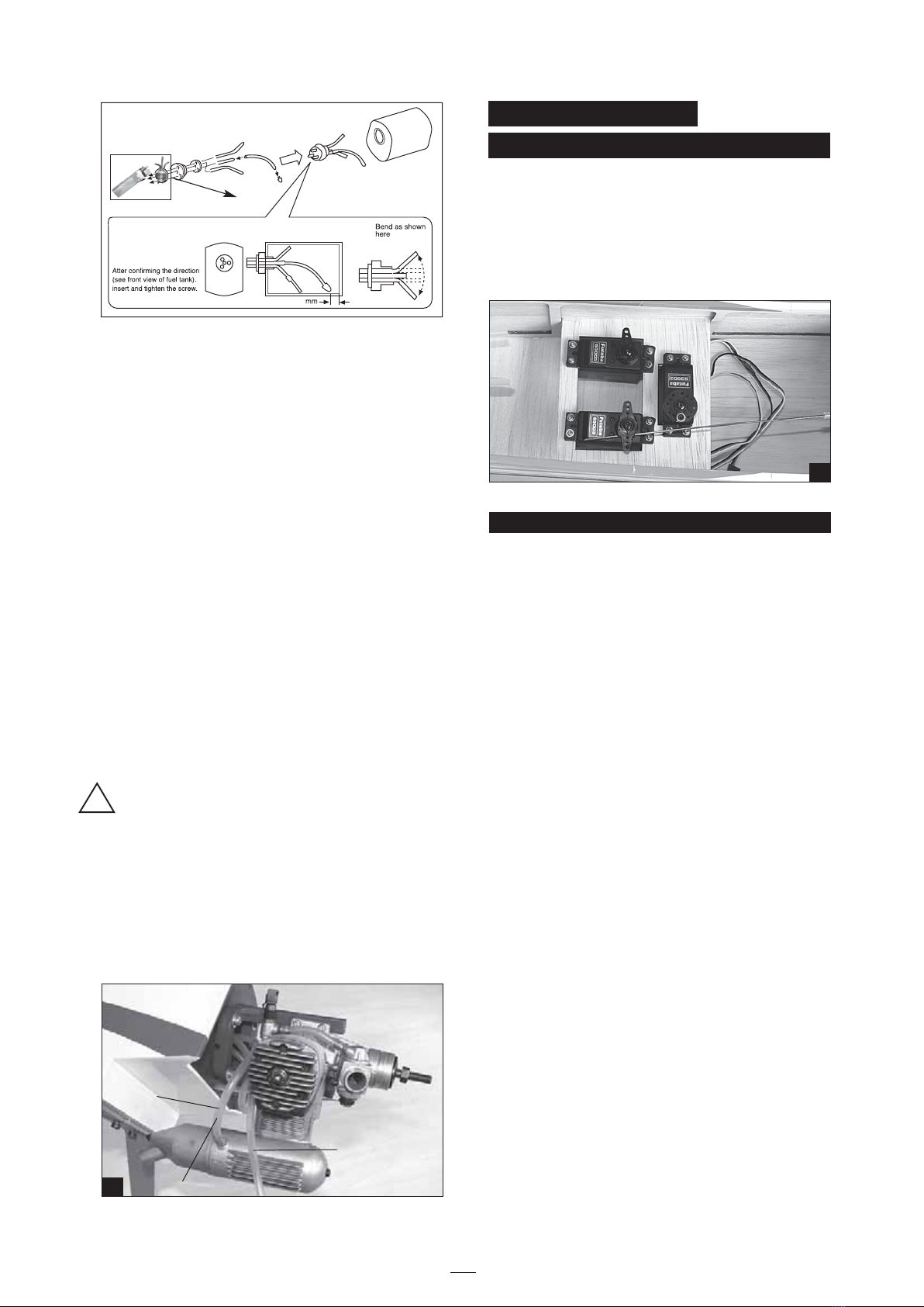
SERVO INSTALLATION
INSTALLING THE FUSELAGE SERVOS
1. Install the rubber grommets and brass collets
into the elevator, rudder and throttle servos. Test
fit the servos into the servo tray. Trim the tray if
necessary to fit your servos
2. Mount the servos to the tray using the mounting
screws provided with your radio system.
INSTALLING THE ELEVATOR PUSHROD
PARTS REQUIRED
· (1) Wire pushrod.
· (2) Clevis
· (2) Silicone tube
· (1) Nylon snap keeper
· (2) Nylon control horn w/plate
· (4) 2mm x 14mm sheet metal screw
· (2) Elevator pushrod
1. Locate the pushrod exit slot on the right side
and left side of the fuselage. It is located slightly
ahead and below the horizontal stabilizer.
2. Carefully cut away the covering material from
the slot.
3. Working from inside the fuselage, slide the
threaded end of the pushrod until it reaches the
exit slot. Carefully reach in with a small screw
driver and guide the pushrod out of the exit slot.
4. Install the clevis on the elevator pushrod. Make
sure 6mm of thread shows inside the clevis.
5. The control horn should be mounted on the
bottom, left side and right side of the elevator at
the leading edge, in line with the elevator
pushrod.
6. Drill two 1,6mm holes through the elevator using
the control horn as a guide and screw the
control horn in place.
7. Attach clevis to the third hole in the control horn.
Install a silicone tube on the clevis.
8. Locate one nylon servo arm, and using wire
cutters, remove all but one of the arms. Using a
2mm drill bit, enlarge the third hole out from the
center to accommodate the elevator pushrod wire.
9. Plug the elevator servo into the receiver and
center the servo. Install the servo arm onto the
servo. The servo arm should be perpendicular to
the servo and point toward the middle of the
fuselage.
To carburator
To muffler
To vent Tube
27
28
8