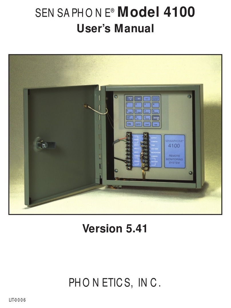
Phonetics SENSAPHONE EXPRESS II User manual

SENSAPHONE®
EXPRESS II
USER’SMANUAL
version 2.02
Phonetics, Inc.

Every effort has been made to ensure that the information in this document is
complete, accurate and up-to-date. Phonetics, Inc. assumes no responsibility
for the results of errors beyond its control. Phonetics, Inc. also cannot
guarantee that changes in equipment made by other manufacturers, and
referred to in this manual, will not affect the applicability of the information
in this manual.
Copyright 1997 by Phonetics, Inc.
Second Edition, version 2.02, September 2000.
Written and produced by Phonetics, Inc. Please address comments on this
publication to:
Phonetics, Inc.
901 Tryens Road
Aston, PA 19014
Sensaphone is a registered trademark of Phonetics, Inc.
Touch Tone is a registered trademark of AT&T.

iii
Contents
IMPORTANT SAFETY INSTRUCTIONS....................................................................................... i
CAUTION............................................................................................................................................ii
CHAPTER 1: INTRODUCTION............................................... 1
PROGRAMMING Express II ............................................................................................................................................1
ABOUTTHIS MANUAL ....................................................................................................................................................1
CHAPTER 2: INSTALLATION................................................. 3
OPERATING ENVIRONMENT .......................................................................................................................................3
MOUNTING Express II......................................................................................................................................................3
STRAIN RELIEF ................................................................................................................................................................4
POWERING UP ..................................................................................................................................................................4
GROUNDINGAND POWER SURGE PROTECTION ..................................................................................................4
BACKUP BATTERY ...........................................................................................................................................................4
TURNING EXPRESS II ON ..............................................................................................................................................5
POWER SUPPLIES ............................................................................................................................................................6
RS232 PRINTER PORT .....................................................................................................................................................6
FCC REQUIREMENTS .....................................................................................................................................................7
NOTICE ...............................................................................................................................................................................7
CHAPTER 3: INPUTS................................................................ 9
HOW THE INPUTSWORK...............................................................................................................................................9
LEDs ...................................................................................................................................................................................10
CONFIGURING THE INPUTS .......................................................................................................................................10
WIRINGTHE INPUTS ....................................................................................................................................................11
STRAIN RELIEF ..............................................................................................................................................................14
SHIELDEDWIRE.............................................................................................................................................................14
WIRE LENGTH ................................................................................................................................................................14
INSTALLING INPUT EXPANSION CARDS ................................................................................................................15
INPUT SPECIFICATIONS ..............................................................................................................................................16
2.8K THERMISTOR LOOK-UP TABLE .......................................................................................................................17
10KTHERMISTOR LOOK-UPTABLE ........................................................................................................................18
CHAPTER 4: OUTPUTS.......................................................... 19
HOW THE OUTPUTSWORK ........................................................................................................................................19
WIRINGTHE OUTPUTS ................................................................................................................................................19
STRAIN RELIEF ..............................................................................................................................................................20
INSTALLING OUTPUT EXPANSION CARDS............................................................................................................20
RELAY OUTPUT SPECIFICATIONS ...........................................................................................................................21
CHAPTER 5: PROGRAMMING ............................................ 23
MOVING THROUGHTHE MENUS ..............................................................23
PROGRAMMING PHONE PARAMETERS................................................24
Calling Schedule ............................................................................................................................... 24
Phone Contacts ................................................................................................................................. 26
CommunicationsType ...................................................................................................................... 26
Special Dialing Codes ....................................................................................................................... 26
Phone Contacts: ................................................................................................................................ 26
DIAL OUT.........................................................................................................28
Dialing Method ................................................................................................................................. 28

iv Sensaphone®Express 2 User's Manual
Retries on Busy ................................................................................................................................. 28
Message Repeat................................................................................................................................. 28
Maximum Number of Calls ............................................................................................................. 29
Call Delay Time................................................................................................................................. 29
Intercall Delay Time ......................................................................................................................... 29
DIAL IN.............................................................................................................30
Rings UntilAnswer ........................................................................................................................... 30
TAD enable/disable ........................................................................................................................... 30
Calling Express II with TAD Enabled..............................................................................................................................31
MESSAGES........................................................................................................................................................................32
INPUTS..............................................................................................................33
Enable/Disable Inputs....................................................................................................................... 33
InputType ......................................................................................................................................... 33
RecognitionTime .............................................................................................................................. 34
High/Low Limits ............................................................................................................................... 34
Alarm Reset Time ............................................................................................................................. 35
Dial Out Selection ............................................................................................................................. 35
Calibration ........................................................................................................................................ 35
ResetValue......................................................................................................................................... 35
SOUND ..............................................................................................................36
Listen-inTime ................................................................................................................................... 36
Sound Monitoring............................................................................................................................. 36
Sound Sensitivity............................................................................................................................... 36
RecognitionTime .............................................................................................................................. 36
Alarm Reset Time ............................................................................................................................. 37
Dialout Selection ............................................................................................................................... 37
Mute Local Speaker.......................................................................................................................... 37
POWER .............................................................................................................38
POWER PARAMETERS................................................................................................................. 38
AC POWER....................................................................................................................................... 38
Failure monitoring ............................................................................................................................ 38
Power Recognition time.................................................................................................................... 38
Alarm reset time ............................................................................................................................... 38
Dialout Selection ............................................................................................................................... 38
BATTERY.......................................................................................................................................... 39
Battery monitor................................................................................................................................. 39
Alarm reset time ............................................................................................................................... 39
Dialout selection................................................................................................................................ 39
OUTPUTS .........................................................................................................41
DATA LOG ........................................................................................................42
Input/Output Log ............................................................................................................................. 42
Activity Log ....................................................................................................................................... 42
SYSTEM............................................................................................................43
Password ............................................................................................................................................ 43
Date and time .................................................................................................................................... 43
Acknowledgment code...................................................................................................................... 43

v
Halt mode delay time........................................................................................................................ 43
Callback acknowledgment ............................................................................................................... 44
Call Cancel ........................................................................................................................................ 44
Auto Test ............................................................................................................................................ 44
Unit Reset .......................................................................................................................................... 44
Unit Configure .................................................................................................................................. 44
SECURITY........................................................................................................45
To Lock .............................................................................................................................................. 45
To Unlock........................................................................................................................................... 45
CHAPTER 6: OPERATION..................................................... 47
Alarm Detection, Dial-out andAcknowledgment ..........................................47
CHAPTER 7: OTHER KEYPAD FUNCTIONS .................... 53
INQUIRING...................................................................................................................................... 53
Inquire Status....................................................................................................53
InquireAlarms ..................................................................................................54
Halt Mode DelayTime......................................................................................54
CHAPTER 8: REACHING EXPRESS II BYTELEPHONE..... 55
Phone-in Parameters ........................................................................................55
The Main Menu.................................................................................................55
Special Keys.......................................................................................................56
PHONE CONTACT LIST ...............................................................................57
PROGRAMMING SUMMARY......................................................................59
APPENDIXA: TROUBLESHOOTING........................................................71
APPENDIX B:ACCESSORIES ......................................................................75
APPENDIX C: ENGINEERING SPECIFICATIONS.................................77
APPENDIX D: RETURNING THE EXPRESS II FOR SERVICE.............83
WARRANTY.....................................................................................................85

i
Safety Instructions
Important Safety Instructions
Your Sensaphone Express II has been carefully designed to give you years of
safe, reliable performance. As with all electrical equipment, however, there are
a few basic precautions you should take to avoid hurting yourself or damaging
the unit:
• Read the installation and operating instructions in this manual carefully. Be sure
to save it for future reference.
• Read and follow all warning and instruction labels on the product itself.
• To protect the Sensaphone Express II from overheating, make sure all openings
on the unit are not blocked. Do not place on or near a heat source, such as a
radiator or heat register.
• Do not use your Sensaphone Express II near water, or spill liquid of any kind
into it.
• Be certain that your power source matches the rating listed on the AC power
transformer. If you’re not sure of the type of power supply to your facility,
consult your dealer or local power company.
• Do not allow anything to rest on the power cord. Do not locate this product
where the cord will be abused by persons walking on it.
• Do not overload wall outlets and extension cords, as this can result in the risk of
fire or electric shock.
• Never push objects of any kind into this product through ventilation holes as
they may touch dangerous voltage points or short out parts that could result in a
risk of fire or electric shock.
• To reduce the risk of electric shock, do not disassemble this product, but return
it to Phonetics’Customer Service, or another approved repair facility, when any
service or repair work is required. Opening or removing covers may expose you
to dangerous voltages or other risks. Incorrect reassembly can cause electric
shock when the unit is subsequently used.
• If anything happens that indicates that your Sensaphone Express II is not
working properly or has been damaged, unplug it immediately and follow the
procedures in the manual for having it serviced. Return the unit for servicing
under the following conditions:
1. The power cord or plug is frayed or damaged.
2. Liquid has been spilled into the product or it has been exposed to water.
3. The unit has been dropped, or the enclosure is damaged.
4. The unit doesn’t function normally when you’re following the operating
instructions.

ii Sensaphone®Express II User's Manual
• Avoid using a telephone (other than a cordless type) during an electrical storm.
There may be a remote risk of electric shock from lightning.
• Do not use the telephone to report a gas leak in the vicinity of the leak.
CAUTION
To reduce the risk of fire or injury to persons, read and follow these instructions:
1. Use only the following type and size battery: Sealed lead-acid 12v 3.0 AH.
2. Do not dispose of the battery in a fire. The cell may explode. Check with local
codes for possible special disposal instructions.
3. Do not open or mutilate the batteries. Released electrolyte is corrosive and may
cause damage to the eyes or skin. It may be toxic if swallowed.
4. Exercise care in handling battery in order not to short the battery with conduct-
ing materials such as rings, bracelets, and keys. The battery or conductor may
overheat and cause burns.
If you experience trouble with this equipment, or you need information on obtaining
service or repairs, please contact:
Phonetics, Inc.
901 Tryens Road, Aston, PA 19014
(610) 558-2700
Fax: (610) 558-0222
www.sensaphone.com

1Chapter 1: Introduction
CHAPTER 1: INTRODUCTION
Welcome to the Sensaphone Express II by Phonetics, Inc. Express II is a powerful environmen-
tal and process monitoring system. It handles your current monitoring, alarm and control needs,
and is able to grow when your application grows.
Express II comes standard with 8 universal input channels and one built-in relay output. Input
capacity is expandable up to 40 channels (on 5 cards). Output capacity may be expanded up to
16 channels (on two cards), in which case input is limited to 24 channels (3 cards).
Express II can call up to 48 Phone Contacts, using pulse or Touch-Tone dialing. Dialing Sched-
ules and Phone Contact List features enable you to create a priority dialing list depending on
which input is alarm-activated, the time of day, and day of week. Call progress detection en-
sures that no time is wasted on busy signals and no-answers during the dialout sequence.
PROGRAMMING Express II
Express II’s unique programming style allows you to access all programmable parameters
quickly and easily. The parameters are organized into 10 categories. From there, programming
is completely voice guided in a menu-style format. You simply enter the category number for the
parameters you want to program and enter values as prompted. All programming can be
accomplished using the local keypad on the unit, or remotely using a Touch-ToneTM phone.
The Express II has a one-year limited warranty. Within the packaging will be a Warranty Regis-
tration card. Please take the time to fill this out and mail. The warranty is explained in the back
of this manual.
If any questions arise during installation or operation, please contact:
Phonetics, Inc.
901 Tryens Road
Aston, PA 19014
Phone: (610) 558-2700
FAX: (610) 558-0222
ABOUT THIS MANUAL
This manual comprises the instructions and commands necessary to install and program Ex-
press II. In addition, summary and application chapters are included to help you speed pro-
gramming and to understand Express II’s features.

2Sensaphone®Express II User's Manual
NOTES

3Chapter 2: Installation
CHAPTER 2: INSTALLATION
This chapter provides the information necessary to install the Sensaphone Express II. Correctly
installing the unit will ensure proper functioning and maximum service life. Please read the
entire chapter before attempting installation.
Within the packaging is a Warranty Registration card. Please take the time to fill this out and
mail it. The Limited 1 Year Warranty is explained on the last page of this manual.
OPERATING ENVIRONMENT
Express II should be mounted and operated in a safe environment. Do not mount the unit
where it will be subject to shock and vibration. The temperature range the Express II can
operate in is 32°F to 130°F (0°C to 55°C). If you require Express II to operate in a below
freezing environment, you must take safe and practical measures to keep the unit's temperature
above 32°F or it will not operate reliably.
CAUTION: Express II is a sensitive electronic device. Personnel and work area should be
grounded before handling this device. Do not install Express II near strong electrostatic,
electromagnetic, magnetic or radioactive fields. Do not expose it to fumes or corrosive vapors.
MOUNTING Express II
When you receive Express II, carefully remove it from the box. On the top and bottom of the
enclosure are mounting holes to attach the unit to either a panel or wall. The mounting surface
should be sturdy enough to support 15 lbs. The unit should be mounted using four #12-24 bolts
where appropriate, or four #12 tapping screws. When mounting the unit to a wall make sure the
mounting screws fully engage a solid member, (e.g. a stud), of the support structure. Mount
Express II in an upright position so that you can easily gain access to the front panel. There
must be a power outlet and telephone jack nearby. The dimensions of the full enclosure are:
14.50"H x 13.06"W x 8.31"D. See Figure 1 below:
Figure 1: Mounting dimensions
10.00"
14.94"
.25"
12.25"
10.25"
4.62"

4Sensaphone®Express II User's Manual
STRAIN RELIEF
Strain relief clamps are provided on the Express II enclosure to prevent wiring from being pulled
from the circuit board or damaged when passing through the enclosure. To use the strain relief,
thread wires through the clamp and the clear rubber bushing. Position the bushing in the clamp
and tighten the screws on either side so that the wiring does not move. See Figure 2 below:
top plate
clamp screw
bottom plate
clear rubber bushing
wiring
Figure 2: Strain relief clamp
POWERING UP
Express II is provided with a 12V AC power transformer. This should be plugged into a 117V AC
outlet, +20%, 60HZ.
The transformer is pre-wired to the terminals labelled AC.
GROUNDING AND POWER SURGE PROTECTION
Express II should be earth grounded by connecting a true earth ground to the terminal labeled
EG. This is not essential for Express II to operate, but it is necessary to prevent possible dam-
age by a lightning strike.
The Sensaphone® Express II can be damaged by power surges and lightning through the tele-
phone line and the power supply. Although Express II has built-in surge protection, we strongly
recommend that additional protection be obtained for the unit and for any electronic equipment
that is attached to your power supply and telephone lines. Power surge protection is especially
important if you live in a lightning-prone area. Surge protection is available through Phonetics.
Call for details.
BACKUP BATTERY
Express II has a 12V 3AH sealed lead-acid Gel-Cell rechargeable battery. This will provide
approximately 6-12 hours backup time. Actual backup time will depend upon the number of
input/output cards installed in the unit, the number of sensors being powered from the unit,
temperature, battery age, and dialing activity. The battery comes pre-wired with the red wire
attached to the BAT IN(+) terminal and the black wire attached to the BAT IN(-) terminal.
Express II will automatically charge the battery whenever the power switch is turned on and the
power transformer is plugged in. The unit also includes special circuity to prevent the battery

5Chapter 2: Installation
from being damaged in the event of an extended power outage. When the battery runs down to
9V, the unit will automatically disconnect it, preventing deep-discharge damage. The battery will
remain disconnected until it charges back up to 12.3 volts. The battery should provide 5 years of
service before needing replacement.
NOTE: Have battery serviced by qualified service personnel only.
The main motherboard and plug-in cards also include a 3V lithium battery to retain user-recorded
messages and programming when the unit is turned off. Each battery will provide two years of
backup time while the unit is turned off and up to 10 years of intermittent use.
NOTE: Have the lithium battery serviced by qualified service personnel only.
TURNING Express II ON
Now that Express II has power, the ON-OFF switch may be turned on.
When the unit is turned ON, it will perform a series of diagnostic tests of its internal circuity.
When all of the tests have been completed, the unit will say, "Express II, OK." The unit is now
operating and will respond to keypad commands and answer telephone calls.
12V
+OUT- 24V
+OUT- +MIC-
BAT
+IN- OUTPUT
RELAY
POWER
A B
SENSAPHONE
R
E
XPRESS
II
MONITORING SYSTEM
ABC
2
DIAL OUT
DEF
3
DIAL IN
MNO
6
SOUND
JKL
5
INPUTS
GHI
4
MESSAGES
PRS
7
POWER
TUV
8
OUTPUTS
WXY
9
DATA LOG
ENTER
CODE
HALT ALARM
CANCEL
OPER
0
SYSTEM
INQUIRE
STATUS
ALARMS
LOCK
UNLOCK DISPLAY
1
PHONE
PROGRAM
OFF ON
OFF ON POW
A
Figure 3: On/Off Switch Location

6Sensaphone®Express II User's Manual
PHONE LINE INSTALLATION
Connect Express II to a standard 2-wire analog phone line. Express II dials using pulse or tone,
with loop start only. Express II will operate with all standard telephone systems that accept
pulse or tone dialing and will recognize ringer frequencies from 16 to 60 Hz.
NOTE:
Certain private telephone systems and public switching equipment may not accept Express II
dialing or may generate an unacceptable ring signal. In those cases, a dedicated line may be
required for Express II. Consult the supplier of your telephone system if you encounter prob-
lems.
CAUTION: Never install telephone wiring during a lightning storm. Never install telephone
jacks in wet locations unless the jack is specifically designed for wet locations. Never touch
uninsulated telephone wires or terminals unless the telephone line has been disconnected at the
network interface. Use caution when installing or modifying telephone lines.
POWER SUPPLIES
Express II will provide battery-backed 12 Volts DC (100 mA max.) and 24 Volts DC (400 mA
max.) to power current loops and other external devices.
RS232 Printer Port
Express II comes with a cable and DB25 connector for connection to a serial printer. This can
be used to perform data logging of input values and/or unit activity directly to a printer (see
Chapter 5). You may also print the unit's programming parameters (see Chapter 7). The RJ11
connector at the end of the cable must be connected to the RJ11 jack labeled RS232 on the
main board, located below the access panel. The default baud rate of the RS232 port is 9600
baud. The baud rate may be changed from the System menu under Unit Configuration (see
Chapter 5). The communications protocol is 8 data bits, no parity, and 1 stop bit. Shown below
are the RS232 pin descriptions for the DB25 connector.
Pin Signal Symbol Direction
1 Frame Ground FG N/A
2 Transmitted Data TD From Printer
3 Received Data RD From Express II
6 Data Set Ready DSR From Express II
7 Signal Ground SG N/A
20 Data Terminal Ready DTR From Printer

7Chapter 2: Installation
FCC REQUIREMENTS
PART 68 - This equipment complies with Part 68 of the FCC rules. On the side of the enclosure there is a label that
contains, among other information, the FCC Registration Number and the Ringer Equivalence Number (REN) for this
equipment. You must, upon request, provide this information to your local telephone company.
The REN is useful to determine the quantity of devices that you may connect to your telephone line and still have all of
those devices ring when your telephone number is called. In most, but not all areas, the sum of the REN’s of all
devices connected to one line should not exceed five (5.0). To be certain of the number of devices that you may
connect to your line, you may want to contact your local telephone company to determine the maximum REN for your
calling area.
This equipment may not be used on coin service provided by the telephone company. Connection to party lines is
subject to state tariffs.
Should Express II cause harm to the telephone network, the telephone company may discontinue your service
temporarily. If possible, they will notify you in advance. But if advanced notice isn’t practical, the telephone company
may temporarily discontinue service without notice and you will be notified as soon as possible. You will be informed of
your right to file a complaint with the FCC. The telephone company may make changes in its facilities, equipment,
operations, or procedures where such action is reasonably required in the operation of its business and is not inconsis-
tent with the rules and regulations of the FCC that could affect the proper functioning of your equipment. If they do, you
will be notified in advance to give you an opportunity to maintain uninterrupted telephone service.
If you experience trouble with this equipment, or you need information to obtain service or repairs, please contact:
PHONETICS, INC.
901 Tryens Road
Aston, PA 19014
(610) 558-2700
Fax: (610) 558-0222
for information on obtaining service or repairs. The telephone company may ask that you disconnect this equipment
from the network until the problem has been corrected or until you are sure that the equipment is not malfunctioning.
PART 15 - This equipment has been tested and found to comply with the limits for a Class A digital device, pursuant to
Part 15 of the FCC Rules. These limits are designed to provide reasonable protection against harmful interference
when the equipment is operated in a commercial environment. This equipment generates, uses and can radiate radio
frequency energy and if not installed and used in accordance with the instruction manual, may cause harmful interfer-
ence to radio communications. Operation of this equipment in a residential area is likely to cause harmful interference
in which case the user will be required to correct the interference at his own expense.
Safety Approvals
The Sensaphone Express II Remote Monitoring System (Model 6700) is NRTL listed in compliance with UL Standard
1950 "Information Technology Equipment" and CSA Standard 22.2 #950. The unit is certified by MET Laboratories, a
Nationally Recognized Testing Laboratory (NRTL), and is listed under file number E1 12098.
NOTICE
The Canadian Department of Communications label identifies certified equipment. This certification means that the
equipment meets certain telecommunications network protective operational and safety requirements. The Department
does not guarantee the equipment will operate to the user’s satisfaction.
Before installing this equipment, users should ensure that it is permissible to be connected to the facilities of the local
telecommunications company. The equipment must also be installed using an acceptable method of connection. In
some cases, the company’s inside wiring associated with a single line individual service may be extended by means of
a certified connector assembly (telephone extension cord). The customer should be aware that compliance with the
above conditions may not prevent degradation of service in some situations.

8Sensaphone®Express II User's Manual
Repairs to certified equipment should be made by an authorized Canadian maintenance facility designated by the
supplier. Any repairs or alterations made by the user to this equipment, or equipment malfunctions, may give the
telecommunications company cause to request the user to disconnect the equipment.
Users should ensure for their own protection that the electrical ground connections of the power utility, telephone lines
and internal metallic water pipe system, if present, are connected together. This precaution may be particularly
important in rural areas.
CAUTION: Users should not attempt to make such connections themselves, but should contact the appropriate electric
inspection authority, or electrician, as appropriate.
The Load Number (LN) assigned to each terminal device denotes the percentage of the total load to be connected to a
telephone loop which is used by the device to prevent overloading. The termination on a loop may consist of any
combination of devices subject only to the requirement that the total of the Load Numbers of all the devices does not
exceed 100. For the Sensaphone Express II the Load Number is 7.

9Chapter 3: Inputs
CHAPTER 3: INPUTS
Express II comes standard with 8 universal inputs. The input capacity may be expanded in
additional sets of 8 inputs. There are 5 slots, offering a total of 40 possible universal input
channels. All the inputs--the 8 standard and the expanded sets--can be configured to accept the
following type sensors:
• Normally closed dry contact (digital)
• Normally open dry contact (digital)
• Pulse count
• 4-20 mA (analog)
• 0-5 Volts (analog)
• Temperature
• 2.8K F thermistor (analog)
• 2.8K C thermistor (analog)
• 10K F thermistor (analog)
• 10K C thermistor (analog)
• Time accumulator
The standard 8 input terminal block is located to the right of the built-in keypad in the first card
slot. Above the terminal block are a row of 8 LEDs that indicate the status of the inputs to on-
site personnel.
HOW THE INPUTS WORK
Express II reads the value of each input by measuring the voltage across the input and the
common terminals. When the shunts are positioned for a specific type of sensor, Express II
uses a different circuit to measure the appropriate reading for that sensor. The common Ex-
press II sensor types follow:
Dry Contact - These digital sensors can be either Normally Open or Normally Closed (desig-
nated N.O/N.C). If a normally open sensor becomes closed, a contact occurs. This causes an
alarm. Conversely, if a normally closed sensor becomes open, the contact disappears, and this
condition causes an alarm. Typical dry contact sensors include magnetic reed switches and
water detection sensors. An example would be a security system where a N.C. magnetic switch
opens as a window is raised.
Pulse Count - This configuration will allow the input channel to count pulses. A typical pulse
count sensor is a flow meter that uses a turbine to measure flow by accumulating pulses. Max
pulse rate for this configuration is 1Hz. Compatible with mechanical relays, open drain and open
collector transistor devices.
4-20 mA - This sensor configuration connects the input signal to a 237 Ohm load resistor. This
allows Express II to measure the current at the input. Any powered or unpowered sensor that
puts out 4-20mA can be wired. Any input range can be specified by the user. Typical sensors
include pressure gauges, analog flow meters, and temperature gauges. Input resolution is 12
bits.

10 Sensaphone®Express II User's Manual
0-5 Volts - This configuration connects the input signal directly to Express II's analog to digital
converter for measuring the output of 0 to 5V transducers. Any sensor that puts out 0-5V can be
wired. Any input range can be specified by the user. Typical sensors include pressure gauges,
voltage meters, and flow meters. Express II can read the voltage between 0 Volts and 5 Volts in
increments of .00122 Volts. Input resolution is 12 bits.
Thermistor - Two kinds of thermistors may be used with Express II: a 2.8K thermistor or a
10K thermistor. The range for an input measuring temperature for 2.8k is –65.0°to 93.33°C
(–85°F to 200°F), and for 10k is –62.22°C to 148.89°C (–80°F to 300°F) . This configuration
type connects the input signal to a 5V reference through a 6.34K pull-up resistor.
Time accumulator - The time accumulator works only with N.O. Dry Contacts. As the name
suggests, it will accumulate and tally the total amount of time--in hours, minutes, and seconds--
that the input sensor is in the closed position. This would be useful, for instance, in maintaining
total run time for a given device.
LEDs
Each input has a corresponding LED that indicates input status. The LEDs are located above
the terminal block. When an LED is
steady green
, that indicates that the input is OK and no
alarms exist. When an LED is
blinking green
, the input is in alarm condition, but the preset
recognition time has not been met to qualify as an unacknowledged alarm. When an LED is
blinking red
, that indicates that an unacknowledged alarm exists on the corresponding input.
When an LED is
steady red
, it indicates that an alarm has been acknowledged but still exists on
the corresponding input. If the input is disabled, the LED goes off for that input. NOTE: If the
LED changes from blinking green directly to steady red, the input is not set up properly to dial
out with an alarm.
CONFIGURING THE INPUTS
Each of the inputs must be configured so that Express II will know what type of signal it must
read. To configure the inputs, you must position the shunts that are located on the input card
directly above the input terminal block. The inputs may be set in one of three configurations:
1. 4-20mA
2. Thermistor, dry contact, or pulse
3. 0-5V
1. To configure the input as 4-20mA, place the shunt to enclose the two bottom pins (B position).
2. To configure the input as thermistor, dry contact, or pulse, place the shunt to enclose the two
top pins
(A position).
3. To configure the input as 0-5V, remove the shunt.
See Figure 4:

11Chapter 3: Inputs
B
1
2
3
A
B
A
B
A
4-20mA
configuration
Thermistor-type
configuration
0-5V configuration
(shunt removed)
Figure 4: shunt configurations
WIRING THE INPUTS
To use a dry contact or temperature sensor on an input, wire one lead to the numbered screw of
input terminal and the other lead to the corresponding common screw. See Figure 5:
Input terminal
Dry contact sensor
R
E
D
W
I
R
E
B
L
A
C
K
W
I
R
E
+
_
C
7
C
8
C
6INPUT
COMMON
INPUT
INPUT
COMMON
COMMON
Figure 5: Dry contact sensor
To use a 4-20mA sensor on an input, you must supply power to it. You may power a 4-20mA
sensor using the Express II internal power supply, or you may wire the sensor to an external
power supply.
To use the
internal
power supply, wire the positive lead from the sensor to the unit 24V power
supply. Wire the negative lead to a numbered input terminal screw. See Figure 6.
NOTE: The number of internally powered sensors will affect battery backup time during a power
failure.

12 Sensaphone®Express II User's Manual
4-20mA sensor
R
E
D
W
I
R
E
B
L
A
C
K
W
I
R
E
+
_
12V
+OUT- 24V
+OUT- +MIC-
BAT
+IN- RELAY
NO COM NC
OFF ON POWER
SENSAPHONE
R
E
XPRESS
II
MONITORING SYSTEM
ABC
2
DIAL OUT
DEF
3
DIAL IN
MNO
6
SOUND
JKL
5
INPUTS
GHI
4
MESSAGES
PRS
7
POWER
TUV
8
OUTPUTS
WXY
9
DATA LOG
ENTER
CODE
HALT ALARM
CANCEL
OPER
0
SYSTEM
INQUIRE
STATUS
ALARMS
LOCK
UNLOCK DISPLAY
1
PHONE PROGRAM
Input terminal
C
10
C
11
C
9INPUT
COMMON
INPUT
INPUT
COMMON
COMMON
(+)
Figure 6: 4-20mA transducer using internal power supply
To use an
external
power supply, wire the positive lead from the sensor to the positive terminal
on the external power source. Wire the negative lead from the sensor to a numbered input
screw on Express II. Next, connect the power supply to Express II by wiring the negative
terminal on the power supply to the corresponding common screw on Express. See Figure 7.

13Chapter 3: Inputs
COMMON
COMMON
COMMON
Input terminal
C
10
C
11
C
9INPUT
INPUT
INPUT
R
E
D
W
I
R
E
+
4
-
2
0
m
A
SE
N
S
O
R
W
I
R
E
Dry contact sensor
B
L
A
C
K
W
I
R
E
_
4
-
2
0
m
A
SE
N
S
O
R
W
I
R
E
EXTERNAL
POWER
SOURCE (-)(+)
Figure 7: 4-20mA sensor using external power source
To use a 0-5V sensor with Express II, wire the sensor signal lead to a numbered terminal screw
on the unit. Then, wire the sensor common to the corresponding common screw on Express II.
See Figure 8.
COMMON
COMMON
COMMON
Input terminal
C
10
C
11
C
9INPUT
INPUT
INPUT
0-5V
Signal
Common
Figure 8: 0-5V sensor
Table of contents
Other Phonetics Measuring Instrument manuals