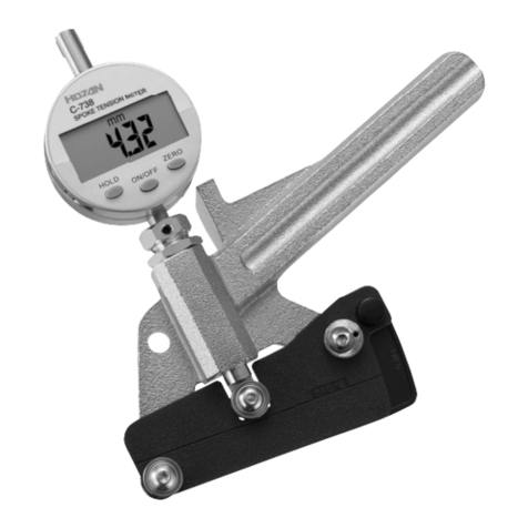
HOZAN C-737 User manual

1
11
1
仕
仕仕
仕
様
様様
様
外形寸法
重量
170(W)×120(H)×30(D)㎜
330g
適応スポーク #13、 #14、#15(プ ーン)
C-737
取扱説明書
取扱説明書取扱説明書
取扱説明書
このたびはホーザン C-737 スポークテンションメーター をお買い上
げいただき、 ことにありがとうござい す。この取扱説明書をよくお読
みになり、正しくお使いください。 た、お読みになったあとも大切に保
管してください。
スポークテンションメーター
スポークテンションメータースポークテンションメーター
スポークテンションメーター
各部
各部各部
各部の
のの
の名称
名称名称
名称と
とと
と入組明細
入組明細入組明細
入組明細
ゼロ調整リング
ハンドル
ダイヤルゲージ
測定子
支持子
圧子
換算表
※2ページ 注意
の 1.をよくお読み
ください。
付属品
付属品付属品
付属品
注意文
注意文注意文
注意文の
のの
の警告
警告警告
警告マークについて
マークについてマークについて
マークについて
ご
ごご
ご使用上
使用上使用上
使用上の
のの
の注意
注意注意
注意
この取扱説明書ではご使用上の注意事項を次のように区別しています。
警告
警告 警告
警告 …重傷をともなう重大事故の発生を想定してのご注意
注意
注意 注意
注意 …傷害や物的損害を想定してのご注意
なお、注意
注意注意
注意として記載されていても、あるいは特に記述がなくても、状況に
よっては重大な結果をまねく恐れがあります。正しく安全にご使用ください。
本器は自転車用スポーク#13・#14・#15(プ ーンタイプ)の張力を簡易
測定するための専用器具です。 この目的以外には使用しないでください。
1.本器では読み取ったたわみ寸法を圧力に換算してスポークの
張力を求め す。換算値は一品ごとに異なるので、個別に公的
検査を受けて換算表を作成しており す。換算表は大切に保
管してください。
万一換算表を紛失された場合は本器の再検定が必要となり す。
2.各部のネジは絶対に締めたりゆるめたりしないでください。調整
が狂い、正しい測定値が得られなくなり す。
万一調整が狂った場合は再検定が必要となり す。
3.本器は精密な測定機器ですので、取り扱いには十分注意してく
ださい。投げたり落としたりし すと故障の原因となり す。
4.本器の分解、および改造は絶対におやめください。故障の原因
となり す。
5.本器は自転車用スポーク#13・#14・#15(プレーンタイプ)
の張力測定器です。これ以外のサイズやエアロスポークなどの
特殊なスポークは測定でき せん。
注意
注意注意
注意
測定工具
測定工具測定工具
測定工具について
についてについて
について
本器をはじめとする測定工具は定期的な検査・調整が必要です。
使用頻度により、検査・調整をおこなう時期に差はあり すが、目安
として1年に1回の検査・調整をおこなうのが理想的です.
なお、検査・調整については当社にて承っており す。ご用命の際は
当社代理店 でお問い合わせください。
2
22
2

3
33
3
ダイヤルゲージのリングを わして
ゼロ調整をし す。(リングと目盛板
は一緒に回転し す。)
1
11
1
2
22
2
3
33
3
ご
ごご
ご使用方法
使用方法使用方法
使用方法
約60mm
測定は車輪両側のリムの内周を
それぞれほぼ3等分する3カ所の、
リムから約60mmの位置に測定子
をあてておこない す。
測定子が上記位置にくるように支
持子をセットし す。
4
44
4
支持子をセットした ハンドルをゆっくりと下げ す。測定子の
溝をスポークに合わせながら圧子をスポークに接触させ す。
圧子は必要以上にスポークに強く押しつけないでください。
実際の張力との誤差が生じ す。
5
55
5
圧子を接触させた で、ダイヤル
ゲージの指針を読み取り す。右の例
では92となり す。
ご
ごご
ご使用方法
使用方法使用方法
使用方法
6
66
6
換算表のグラフのX軸ダイヤル
ゲージの読みに5
55
5で得られた値(こ
の例では92)を当てはめ、Y軸
スポークの張力を割り出し す。
この場合
#14スポーク=300N
#15スポーク=600N
になり す。
※このグラフは参考です。実際に
は別途添付の換算表をご使用
ください。
ス
ポ
ー
ク
の
張
力
(
N
)
(
1
N
=
0
.
1
0
2
k
g
f
)
ダイヤルゲージの読み(1/100mm)
・オフセット組み(通称おちょこ組み)の場合
7
77
7
測定結果を下表に照らし、判定し す。
前輪
前輪前輪
前輪
後輪
後輪後輪
後輪
車輪の径(呼び) 張力
22を超え もの 平均400N以上
22以下 平均300N以上
フリーホイール側 反対側
平均400N以上 平均300N以上
※上記表中、平均とあるのは3カ所の測定点を測定した合計数
値を3等分したものです。ただし、1カ所でも150N以下のもの
があってはいけ せん。(JIS D 9301 準拠)
4
44
4
16.01
本社 〒556-0021 大阪市浪速区幸町1-2-
12
TEL(06)6567-3111 FAX(06)6562-0024
補修部品のご購入は ホーザンの通信販 が便利です。
ホーザン 通信販売
検索
検索検索
検索
または ホーザンwebページにアクセス

C-737
INSTRUCTION MANUAL
SPOKE TENSION METER
Identification of parts and contents
Thank you for purchasing the HOZAN C-737 SPOKE TEN-
SION METER. With proper care and handling, this fine
instrument will provide years of trouble-free operation. Please
read this entire instruction manual carefully before attempting
to place this instrument in service. Please keep this instruction
manual available for reference.
Dial gauge
Zero adjustment ring
Handle
Contact pin
Pi ot pin
Clamp
1
11
1
Specifications
Dimensions
Weight
170(W)×120(H)×30(D)mm
330g
#13, #14, #15 (plain)
Applicable spoke
Con ersion chart
*efer to the
clause 1. of
Caution
on page 2.
Accessory
Precautions
The C-737 is designed only for measurement of the tension of #13,
#14 and #15 bicycle spokes. Do not use for any other purpose.
1.The spoke tension is acquired in converting the suppleness
measure of the spoke into pressure value. The conversion
chart is individually provided with each C-737 trough the official
calibration, because each instrument has individual converting
value. Keep the conversion chart in a safe place together with
the C-737.
If you lose the conversion chart, the C-737 unit will need to be
re-calibrated.
2.Never loosen or tighten any of the screws, as doing so could
interfere with the adjustment so that the measurement results
no longer be accurate.
3.The C-737 is a precision tool, so handle it with care. Do not
throw it or drop it, otherwise it could not longer function
correctly.
4.Never attempt to disassemble or modify the C-737, otherwise it
could no longer function correctly.
5.The C-737 is to be used for measuring the tension of #13, #14
and #15 bicycle spokes only. It cannot be used to measure
different size or special type of spokes such as aero spokes.
Caution
These symbols are used throughout the instruction manual to alert
the user to potential safety hazards as follows :
Warning … Notice when incorrect handling could cause
the user's death or serious injury.
Caution … Notice when incorrect handling could cause injury
to the user or material damage.
Even if the instructions do not have Caution mark, there are
some possibilities for a serious situation. Follow the instructions.
Warning and caution symbols
Note on using this instrument
Measuring instrument such as the C-737 require periodic calibration.
The length of time between each calibration will vary depending on
the frequency of use, but in general, calibration should ideally be
carried out at least once a year. For any calibration requirement,
please contact HOZAN dealer.
2
22
2

5
55
5
Take a reading from the dial gauge
when the contact pin touches the spoke.
In this example, the reading is 92.
3
33
3
Operation
Approx. 60 mm
Rotate the ring of the dial
gauge until it reads zero. (The
ring and gauge rotate together.
1
11
1
2
22
2
3
33
3
Carry out measurement on the
both sides of the wheel, applying
the pi ot pin at the points that
approximately trisect the
circumference of the rim, 60 mm
in from the rim.
4
44
4
With the clamp in place, slowly lower the handle until the
contact pin touches the spoke.
Do not press the contact pin against the spoke with more
than the required force. If force it too great, the tension
measurement obtained could differ from the actual
tension.
Hook the clamp so that
the pi ot pin will come to
the point gi en abo e.
4
44
4
16.01
Operation
6
66
6
Find the point on the X axis (A)
in the con ersion chart of 92 (in
this example) gotten in step 5.
Then find the corresponding
spoke tension on the Y axis (B).
In this sample:
#14 spoke=300N
#15 spoke=600N
*The graph shown here is for
reference only. Be sure to
use the attached con ersion
chart.
(
B
)
S
p
o
k
e
t
e
n
s
i
o
n
[
N
]
(
1
N
=
0
.
1
0
2
k
g
f
)
(
B) Dial gauge reading (1/100 mm)
*A erage tension : Measured in three places and di iding
its total by 3. No single point with a tension of 150N or
lower are allowed. (Based upon JIS D 9301)
7
77
7
Judge the wheel balance checking the measuring results
acquired in step 6 referring to the following table.
Front wheel
Rear wheel
Wheel diameter Tension
More than 22” Average
400N or more
22” or less Average 300N
Freewheel side Opposite side
Average
400N or more Average
300N or more
For wheels with offset assembl
1-2-12 Saiwaicho, Naniwa-ku, Osaka 556-0021, Japan
Tel : +81-6-6567-3111 F a x : +81-6-6562-0024
Other HOZAN Measuring Instrument manuals
Popular Measuring Instrument manuals by other brands

Chekman
Chekman TK-1000A manual

Dakota Digital
Dakota Digital VHX-67C-CAM-K-B Installation and operation manual

GANN
GANN Hydromette BL UNI 11 operating instructions

horiba
horiba HU-200TB SS-120 instruction manual

Crown
Crown CT44051 Original instructions

Hanna Instruments
Hanna Instruments HI6321 instruction manual