Photogenic PowerLight PL2 Series User manual

Operator’s Manual
For PL2 Series Professional Monolights
PowerLights
PL1250, PL300DR, PL1250DR, PL2500DR
Radio-Sync PowerLights
PLR300DR, PLR1250DR, PLR2500DR
Solair Constant Color PowerLights
PL500DR, PL1000DR
Solair Radio-Sync Constant Color PowerLights
PLR500DR, PLR1000DR
Voltage Smart PowerLights & Solair PowerLights
PLX1250DR, PLX2500DR, PLRX1250DR, PLRX2500DR,
PLX500DR, PLX1000DR, PLRX500DR, PLRX1000DR
Remote Control Systems
Infrared Manual System, Infrared Computer Controlled System,
Wired Manual System, Wired Computer Controlled System
p/n 999525 v.03/09

Thank you for selecting the Photogenic Professional
PowerLight PL2 series. The PL2 series incorporates the newest
electronic components providing improved lighting control,
power setting repeatability and expanded functions. These
products are designed to meet the demanding needs of
professional photographers, and it is our expectation that your
PowerLight and PowerLight accessories will provide you with
years of dependable service.
INTRODUCTION
Each Photogenic PowerLight is a self-contained monolight with a built-in
power supply and light unit. All PowerLights feature a user changeable plug-
in flashtube, and 250 watt modeling lamp. The PowerLights will accept all
Photogenic Quick Change Accessories. Photogenic PowerLights that have the
letter “C” in the model number are equipped with a color corrected flash tube
(example: PL1250DRC).
PL1250 has sliding switches for controlling flash and modeling lamp output.
The PL1250 is not compatible with the infrared power control systems.
DR series lights have push button power level controls and a digital display.
Power levels for flash and modeling lamp can be adjusted in 1/10 or 1/2
f-stop increments.
Solair brand Constant Color series will maintain a constant color temperature
of 5400K ± 100K over an eight f-stop power range.
PLR series lights include a built-in PocketWizard™ radio receiver for wireless
triggering with a PocketWizard™ transmitter (not included).
PLX and PLRX models will operate on any worldwide voltages and
frequencies.
Photogenic Remote Control Systems can be used on all PL2 series PowerLights
and Solair lights except for the PL1250.
Before using your new PowerLight for the first time, please read this manual
carefully to acquaint yourself with the controls and features. This will help you
get the greatest benefit from your new Photogenic monolight and maintain an
efficient and safe operation.
2

SAFETY PRECAUTIONS
Despite the measures that have been taken to make electronic flash equipment
safe, it must be recognized that high voltages and high temperatures do exist
within the power supply/lighting unit. Certain precautions must be observed in
handling the unit. Contact with internal high voltage may result in severe injury or
death.
1. Before installing or removing the flashtube and modeling lamp, be sure this
appliance is turned off, cooled and unplugged from AC power source.
2. Do not touch the glass tubes with bare hands, as normal body oils will shorten
the bulb’s life. Always use a clean cloth or wear gloves to protect your hand
from glass breakage and heat.
3. Do not defeat the purpose to the three-wire cord by disconnecting the ground.
Connect to properly functioning and grounded 3-pin receptacles only. If you
are using an extension cord, be sure the cord has an equivalent or greater
rating and has a ground.
4. Do not insert a screwdriver or other metal objects into the flashtube socket
area or vents. Contact with high voltage may result.
5. Do not operate this appliance with a frayed or damaged line cord. When
replacing or using the unit with an extension cable, be sure the cable has an
equivalent or greater rating and is a properly connected 3-wire grounded
cable.
6. Do not attempt to use this appliance if it has been dropped or damaged, until
a qualified service person has serviced it.
7. Do not operate the unit with a damaged or broken flashtube or modeling
lamp. Do not use flashtubes with broken, cracked or missing glass envelopes.
To prevent damage always use Photogenic specified replacements for the
flashtubes and modeling lamps.
8. Perform no internal service work on this unit. Refer all out of warranty to a
factory authorized service agent or return to factory. If the monolight is under
warranty, return it to the factory only. This will assure the continuation of the
warranty.
9. Do not operate when water is present and from extreme temperature shifts.
If the unit is stored in hot or below freezing temperatures, allow at least one
hour at room temperature before using.
PREPARATION AND BASICS
What’s in The Box?
Each PowerLight comes complete with the following items:
1 - PowerLight Monolight 1 - Power cord
1 - Flash tube 1 - Sync cord
1 - Modeling lamp 1 - Flash tube protector
1 - 7 1/2” Reflector with umbrella knockout 1 - Owner’s Manual
1 - Warranty Card
3

Unpacking
Unpack all items carefully from the carton(s). Do not discard or destroy the packing material
until the equipment has been inspected, assembled, and all parts are accounted for.
After unpacking, all parts should be examined for any damage, which may have been
caused by rough handling during shipment, If any damage is detected, contact the
delivering carrier at once. Claim for damage should be made to the delivering carrier
before destroying packing cartons.
Setup
1. Set up a suitable light stand with a 5/8” top post. Place the stand mounting
adapter of the PowerLight on top of the stand, and secure it with the thumb
screw provided.
All Photogenic PowerLights are designed to be mounted right side up. Mounting
the lights upside down can cause premature capacitor failure. When mounting the
lights overhead or on a rail system, use the appropriate mounting adapter, or
contact the Photogenic repair department to have the mounting adapter mounted on top
of the light.
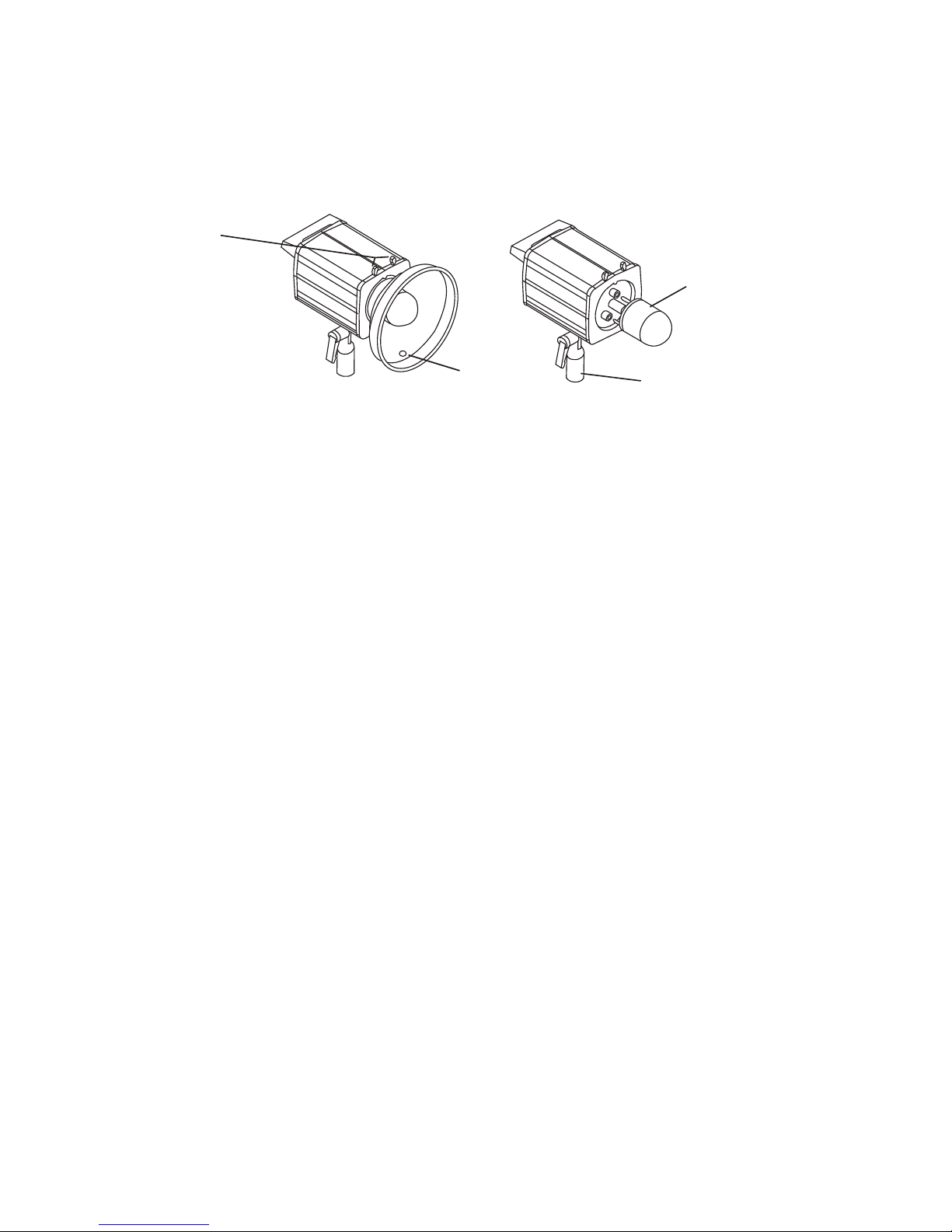
2. Remove the flash tube protector. Squeeze the two quick change levers on top
of the light. Pull the flash tube protector up and out to remove. Set aside.
3. Unpack the modeling lamp. Do not touch the glass with your fingers. Using
a clean cloth or glove to protect your hands, insert the base of the modeling
lamp all the way into the spring loaded center socket on the front of the light,
and twist to the right to secure.
4. Unpack the three pronged flash tube. Using a clean cloth or glove, align the
prongs with the three sockets on the front of the light. The prongs will fit in the
sockets only one way. Push the flash tube until the prongs are firmly seated
in the sockets and the base of the flash tube is in contact with the fronts of the
sockets. When handling flash tubes and modeling lamps always use a clean
cloth or glove to protect your hands from glass breakage or heat.
5. On a hard surface, place the 7 1/2” reflector on its side with the oval
knockout at the bottom of the reflector. Use a screw driver or other metal tool
to push the oval knockout out of the side of the reflector. This oval opening
allows an umbrella shaft to pass through the reflector and be connected to the
umbrella holder on the bottom of the monolight.
6. Attach the reflector. Squeeze the quick change levers on top of the light.
Place the top of the reflector mounting ring under the black tab above the flash
tube. Push the bottom of the mounting ring in place and release the quick
change levers.
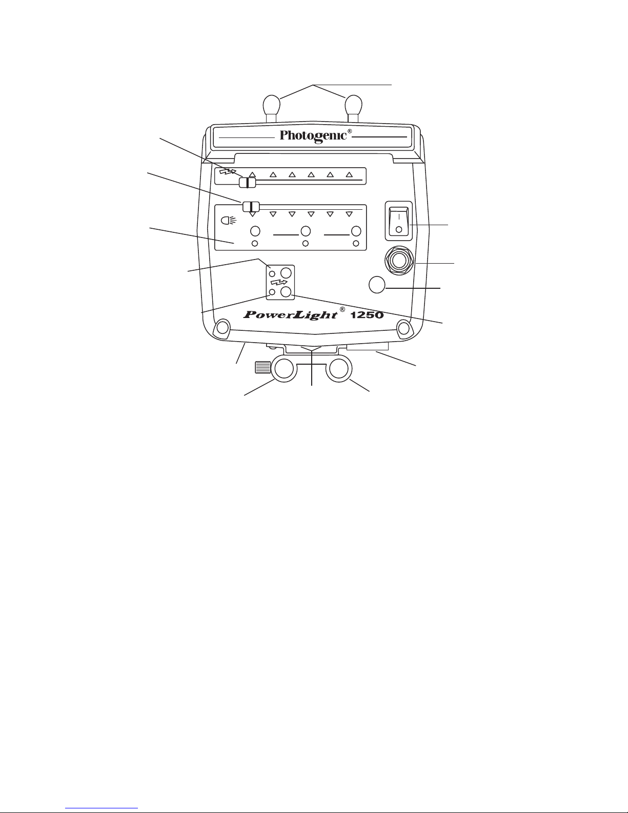
7. Make certain the power switch is in the OFF position.
8. Attach the power cord to the power input on the bottom of the light.
Connect the power cord plug to a grounded 105 - 125 VAC (90 to 250 VAC
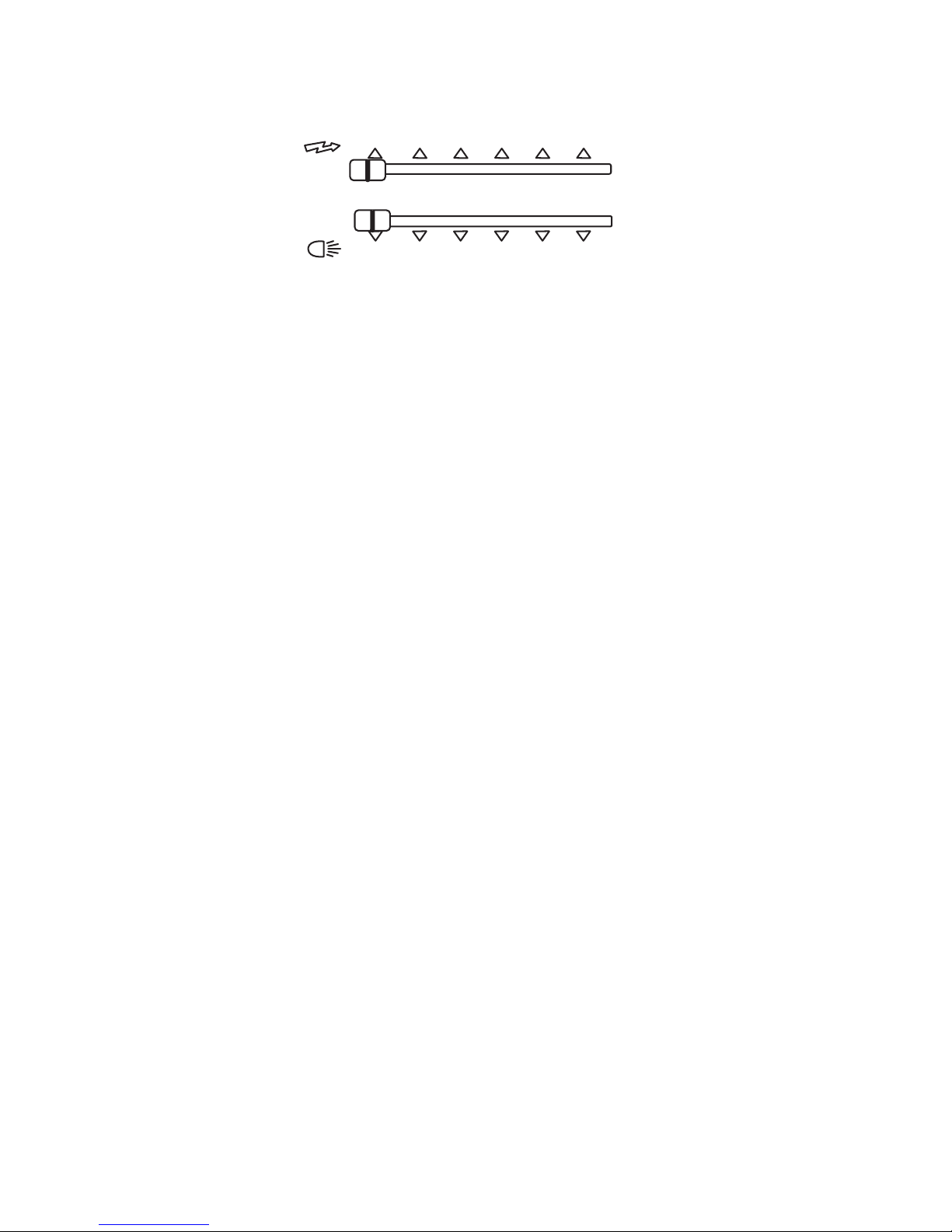
for PLX PowerLights) wall outlet. Turn the power switch ON. The ready light
will light when the unit has charged to the power level set by the flash power control.
9. Note: The additonal weight of large softboxes may cause the light stand to become
unstable. The Photogeinc Adjustable CounterWeight (919148) is the ideal accessory
to improve the balance and stability of the lighting system.
4
Squeeze levers to
mount reflector.
Punch out hole for
umbrella shaft.
Professional plug-in
flashtube.
Mounting adapter.

POWERLIGHT MODEL PL1250
CONTROL PANEL AND BASIC OPERATION
Power Input:
The power required to operate the PowerLight 1250 is 105 to 125 volts AC, 60
Hz, 10 Amp. The power cord has a 125V, 10 Amp. rating. Replacement cords
or extension cords rated for less amperage may overheat and should not be used
with PowerLights.
Circuit Protection:
Circuit protection automatically protects this appliance from excessive damage
due to circuit or component failure. Operation exceeding the rated cycle of the
appliance may cause the fuse to open. (Always replace with same rating of fuse.)
An additional thermal protector is located inside the PowerLight and may open,
if the rated duty cycle is exceeded. A cooling off period of 10 to 45 minutes is
required to reset the thermal protector.
To replace a blown fuse (power cord must be disconnected), simply unscrew the
fuse holder cap (bottom of unit) and replace the exposed fuse with a new fuse.
If fuses continue to blow, contact your dealer or qualified service person. (See
specification section for fuse replacements).
Power Switch:
The power switch controls the AC power to both the modeling and flash circuits.
You have the option to turn-off the modeling circuit independently.
5
F
LASH
I
NDICATION
T
EST
O
N
/
O
FF
R
EADY
F
LASH
M
ODEL
M
ANUAL
MA D E I N U.S.A.
S
LAVE
S
YNC.
T
RACK
S
ET
F
ULL
O
N
/
O
FF
1
/
32 1
/
16 1
/
8 1
/
4 1
/
2F
ULL
WARNING!
D
O NOT OPERATE
WITHOUT GLASS
LAMP COVER
IN PLACE.
Power Input
Connector
Optical Slave Sensor
Sync Outlet
Power Switch
Quick Change Levers
(Front of Light)
Umbrella Holder Fuse Holder
Fan
Test Button
Modeling Lamp
Power Control
Ready Light
Flash Indication Button
Flash Power
Control
Modeling Lamp
Controls
Counterweight
Holder

Flash Power:
All settings and controls of the PowerLight 1250 are extremely stable and
repeatable due to the use of an internal microcomputer. The PowerLight 1250 is
adjustable from 16 watt seconds to 500 watt seconds.
To adjust the PowerLight 1250 to its lowest flash power setting (16 watt seconds),
slide the FLASH control knob all the way to the left.
To adjust the PowerLight 1250 to its greatest flash power setting (500 watt
seconds), slide the FLASH control knob all the way to the right.
Intermediate power settings are continuously variable from lowest power to highest
power.
To adjust the PowerLight 1250 to an exact flash power setting, use the accessory
digital display, PLDD-1 (919177).
Ready Light:
The PowerLight 1250 is fully charged when the READY lamp is on. Lowest power
(16 ws) charge time is a maximum of .5 seconds and at full power (500 ws) time
is a maximum of 1.5 seconds. The unit may be flashed before fully charged.
Modeling Light:
The modeling light has three modes of operation:
1. MANUAL adjustment (press the MANUAL button. LED on) adjusts the
modeling lamp intensity with the MODEL slide control knob. As with
flash power, minimum setting is full left and maximum setting is full
right. The MODEL intensity scale corresponds to the FLASH intensity
scale, measures in f-stops.
2. TRACK mode causes the modeling lamp intensity to track the FLASH setting.
The modeling lamp may be set to full intensity at any FLASH setting, by simply
pressing the TRACK/SET button a second time, (you will notice the TRACK/
SET LED light blink once) with the FLASH control knob in the desired position.
Setting is retained when user returns from another mode.
3. FULL ON/OFF. Press the FULL ON/OFF button to turn the modeling lamp
OFF (LED off) or ON (LED on) at full power.
All mode settings are retained, even after the power has been turned off.
TEST BUTTON:
Press the test button to trigger the flash tube for test purposes.
6
FLASH
M
ODEL
1
/
32 1
/
16 1
/
8 1
/
4 1
/
2F
ULL

POWERLIGHT MODELS PL300DR, PLR300DR,
PL1250DR, PLR1250DR, PLX1250DR, PLRX1250DR,
PL2500DR, PLR2500DR, PLX2500DR and
PLRX2500DR
CONTROL PANEL AND BASIC OPERATION
Power Input:
All PL and PLR model PowerLights will operate on 105 to 125 volts AC, 60 Hz, 10
amps. All PLX and PLRX Voltage Smart PowerLights will operate on 90 to 250 volts
AC, 50 to 60 HZ, 3.5 amps and have a 230 volt power cord with a German/
European plug. Replacement cords or extension cord rated for less amperage
may over heat, and should not be used with the above lights.
Flash Power:
Press the Adjust button to turn on the Flash ws digital display. Adjust the DR
PowerLight Flash power setting using the 1/2 or 1/10 f-stops UP/DOWN arrow
buttons.
Ready Light:
The DR PowerLights are fully charged when the READY lamp is on. For 1000
ws PowerLights the lowest power charge time is a maximum of .8 seconds, and
at full power charge time is a maximum of 3seconds. For 500 ws PowerLights,
the lowest power charge time is a maximum of .5 seconds, and at full power the
charge time is a maximum of 1.5 seconds. The unit may be flashed before fully
charged.
7
F
LASH
I
NDICATION
A
DJUST
M
ADE IN
U.S.A.
S
LAVE
S
YNC.
TRACK
S
ET
F
ULL
O
N
/
O
FF
WARNING!
D
O NOT OPERATE
WITHOUT GLASS
LAMP COVER
IN PLACE.
F
LASH
M
ODEL
R
EADY
O
N
/
O
FF
T
EST
F
LASH
M
ODEL
2
l
l
0
l
WS
WATTS
Power Input
Connector
Counterweight
Holder
Fuse
Holder
Optical Slave Sensor
Sync Outlet
Power Switch
Quick Change Levers
(Front of Light)
Digital Display
Umbrella Holder
Fan
Power Setting Buttons
Test Button
Flash/Modeling Lamp
Adjust Button
Ready Light
Flash On/Off LED
Flash Indication Button
Modeling Lamp On/Off LED

Modeling Light:
The modeling light has three modes of operation:
1. MANUAL Press the ADJUST button to turn the MODEL yellow LED on. Adjust
the modeling lamp intensity using the 1/2 or 1/10 f-stops UP/DOWN arrow
buttons. Pressing the MANUAL button a second time will change the mode to
flash adjustment and is indicated by the illuminated red LED.
2. TRACK mode causes the modeling lamp intensity to track the FLASH setting.
The modeling lamp may be set to full intensity at any FLASH value, by simply
pressing the TRACK/SET button a second time, with the FLASH already set
to desired watt-seconds. Setting is retained when user returns from another
mode.
3. FULL ON/OFF. Press the FULL ON/OFF button to turn the modeling lamp OFF
(LED off) or ON (LED on) at full power.
All mode settings are retained, even after power has been turned off.
Test Function:
Press the TEST button to fire the flash tube for test purposes.
Flash Indication:
This function indicates the flash has fired properly. The flash indication feature will
dim the modeling light to its lowest setting, then intensify slowly to full brightness or
to its original state. This will occur after each flash, even though the modeling light
may be off. This feature is turned ON (LED on) or OFF (LED off) with the FLASH
INDICATION button.
Automatic Flash Dump:
This feature will automatically flash the unit when the FLASH setting is lowered;
otherwise, the internally stored power is discharged through a resistor, before the
unit is READY. Flash Dump is faster. This feature can be turned on or off, by the
user.
Turn FLASH DUMP on: Turn PowerLight AC power off. With unit power off, press
and hold the FULL ON/OFF button. While holding the FULL ON/OFF button,
turn the unit ON and wait until the FULL ON/OFF LED blinks. Release the FULL
ON/OFF button.
Turn FLASH DUMP off: Turn PowerLight AC power off. With unit power off, press
and hold the MANUAL button. While holding the MANUAL button, turn the unit
power on and wait until the MANUAL LED blinks. Next release the MANUAL
button and the MANUAL LED will go off.
Also, each time the AC line power is disconnected or switched off, the flashtube
will flash. This removes most of the flash capacitor charge to prolong the life of the
unit and is a much safer condition for storage, transporting, and replacement of
8

flash tube or modeling lamp. This is a feature, over which the user has no control.
Synchronization and Triggering:
Triggering is accomplished by using a sync cord, built-in photoslave, infrared or
radio triggering device. Other units in the system are then triggered by photoslave
operation. When using a sync cord, it is best to connect the fill light directly to
the camera since it will be positioned furthest back in the studio and will usually
provide sufficient illumination to trigger the other units.
The sync voltage is 12 volts DC on units made before March 31, 2008. For
cameras requiring a sync voltage of less than 12 volts, a sync voltage reduction
device should be used. PowerLights made after March 31, 2008 have a sync
voltage of 5 volts DC.
PocketWizard™ Use For All PLR Models:
All PLR model PowerLights and PLR Solair Lights have built-in PocketWizard™ radio
triggering receivers. Before using the PocketWizard™ system, you must disable
the sync outlet on all lights being triggered by radio. Otherwise, the optical slaves
in the lights will remain active and can inadvertently trigger the lights.
Disable the sync outlet by inserting a 1/4” microphone plug or 1/4” dowel rod
into the 1/4” sync outlet.
PocketWizard™ Setup:
1. Turn on the PocketWizard™ transmitter, and set the “local, both, remote”
switch to either both or remote.
2. Select a channel on the transmitter.
3. Hold the test button on the transmitter down and turn the PowerLight on.
Continue to hold the test button down for 6 seconds in order for the built-in
receiver to recognize the transmitted frequency. Connect the transmitter to the
camera to trigger the lights when the shutter is released. Set your camera
to “manual” Turn off the camera’s TTL infrared exposure meter to prevent
premature flashing. Follow the PocketWizard™ instructions for proper
operating procedures and connection to the camera.
9

OPERATIONAL PARAMETERS
PL1250, PL1250DR, PLX1250DR,
PLR1250DR and PLXR1250DR
Flashing Rate:
The unit recharges quickly, as indicated by the READY light on the control panel.
A quick series of flashes can be obtained within the limits of the recharge time.
Continuous rapid flashing, however, can overheat and damage the flashtube and
internal parts. The maximum recommended rate of flashing depends upon the
power level being used and the amount of operation time. Use the following chart
to serve as a guide for the maximum rate to use in your situation.
10
Power
Level
Full
1/4
1/32
Operating
Time
Continuous
30 minutes
3 minutes
Continuous
30 minutes
3 minutes
Continuous
Sec. Between
Flashes
15
6
4
6
3
2
1.5
Number of
Flashes
Continuous
300
45
Continuous
600
90
Continuous
Exposure Information:
The following charts give the BCPS output for various umbrellas and reflectors.
Coverage angle is given in degrees.
Umbrella
Coverage
Full Power
Half
Quarter
Eighth
Sixteenth
Thirty-Second
32 inch
120 degree
5500
2750
1375
688
344
172
45 inch
120 degree
5583
2792
1396
698
349
174
60 inch
120 degree
5583
2792
1396
698
349
174
Reflector
Diameter
Coverage
Full
Half
Quarter
Eighth
Sixteenth
Thrity-Second
GN@ ASA 100
None
360°
2333
1167
583
292
146
73
110
7 1/2”
35°
25000
12500
6250
3125
1562
781
365
18”
126°
3570
1785
892
446
223
112
137
16”
60°
23333
11667
5833
2916
1458
729
350
24”
145°
4200
2100
1050
525
262
131
150

SPECIFICATIONS
PL1250, PL300DR, PL1250DR, PLX1250DR,
PLR300DR, PLR1250DR and PLXR1250DR
11
General:
Flash Power PL1250, PL1250DR and PLR1250DR ...................
PL300DR .........................................................
Flash Duration ............................................................
Recycle Time ............................................................................
Power Control ..............................................
Modeling Light Power ...........................................................
Modeling Light Control ..................................
Triggering ................................................
Main Supply PL300DR, PL1250DR ........................
Main Supply PLX1250DR ..................................................
Consumption ...................................................
Voltage Stabilization .........................................................................
Overload Protection .........................................
Housing .................................................................................
Weight PL300DR .........................................................................................
Weight PL1250DR ...............................................................................
Weight PLX1250DR .....................................................................................
Dimensions PL300DR, PL1250DR ..............................................
Dimensions PLX1250DR ...........................................................
Flash Tubes and Modeling Lamps:
Flash Tube ..........................................................
Modeling Lamp .......................................................
Fuse PL300DR, PL1250DR ...........................................
Fuse PLX1250DR .....................................................
16 to 500 watt-seconds
4 to 125 watt-seconds
1/1300 second at full power
1/640 second at 1/32 power
0.5 to 1.5 seconds
Range: Full to 1/32 power (6 f-stops).
0.1 f-stop resolution
250 watt Quartz, ESS
Range: Full to 1/32 power (6 f-stops).
0.1 f-stop resolution.
Sync. Jack (5 volts*). Push to test button.
Built-in Photo slave. Radio on PLR models.
105 - 125 VAC, 60 Hz, 10 amps.
230 V, 50 Hz, 10 amps.
0.2 amps idling, 15 amps charging.
± 0.05 f-stop.
Fuse. 3 AG type 15 amp, SLO-BLO.
Extruded Aluminum.
5 lbs.
5 lbs. 8 oz.
6 lbs.
4.5” x 4.5” x 6.75”
4.5” x 4.5” x 8.75”
Plug-in style. Use only Photogenic
C4-15, C4-15C (color corrected),
C4-15F (frosted) and C4-15D
(frosted and color corrected)
250 watt quartz halogen, ESS.
150 watt quartz halogen, ESP.
100 watt quartz halogen, ESR.
3AG type, 15 amp, SLO-BLO
5mm x 20mm, 8 amp, SLO-BLO
* Trigger Voltage = 12 volts on units purchased before JUNE, 2008

OPERATIONAL PARAMETERS
PL2500DR, PLR2500DR, PLX2500DR and
PLXR2500DR
Flashing Rate:
The unit recharges quickly, as indicated by the READY light on the control panel.
A quick series of flashes can be obtained within the limits of the recharge time.
Continuous rapid flashing, however, can overheat and damage the flashtube and
internal parts. The maximum recommended rate of flashing depends upon the
power level being used and the amount of operation time. Use the following chart
to serve as a guide for the maximum rate to use in your situation.
12
Power
Level
Full
1/4
1/32
Operating
Time
Continuous
30 minutes
3 minutes
Continuous
30 minutes
3 minutes
Continuous
Sec. Between
Flashes
15
10
6
6
3
3
3
Number of
Flashes
Continuous
180
30
Continuous
600
60
Continuous
Exposure Information:
The following charts give the BCPS output for various umbrellas and reflectors.
Coverage angle is given in degrees.
Umbrella
Coverage
Full Power
Half
Quarter
Eighth
Sixteenth
Thirty-Second
32 inch
120 degree
11000
5500
2750
1375
688
344
45 inch
120 degree
11166
5583
2792
1396
698
349
60 inch
120 degree
11166
5583
2792
1396
698
349
Reflector
Diameter
Coverage
Full
Half
Quarter
Eighth
Sixteenth
Thrity-Second
GN@ ASA 100
None
360°
4666
2333
1167
583
292
146
160
7 1/2”
35°
50000
25000
12500
6250
3125
1562
515
18”
126°
7140
3570
1785
892
446
223
194
16”
60°
46666
23333
11667
5833
2916
1458
495
24”
145°
8400
4200
2100
1050
525
262
210

SPECIFICATIONS
PL2500DR, PLR2500DR, PLX2500DR and
PLXR2500DR
13
General:
Flash Power .....................................................................
Flash Duration ............................................................
Recycle Time ............................................................................
Power Control ..............................................
Modeling Light Power ...........................................................
Modeling Light Control .............................
Triggering ................................................
Main Supply PL2500DR ........................................
Main Supply PLX2500DR ..................................................
Consumption PL2500DR ....................................
Consumption PLX2500DR ....................................
Voltage Stabilization .........................................................................
Fuse PL2500DR ...........................................................
Fuse PLX2500DR ....................................................
Housing .................................................................................
Weight PL2500DR, PLR2500DR ......................................................................
Weight PLX2500DR, PLXR2500DR .........................................................
Dimensions PL2500DR, PLR2500DR ...........................................
Dimensions PLX2500DR, PLXR2500DR ..........................................
Flash Tubes and Modeling Lamps:
Flash Tube ..........................................................
Modeling Lamp .......................................................
32 to 1000 watt-seconds
1/770 second at full power
1/345 second at 1/32 power
0.8 to 3.0 seconds
Range: Full to 1/32 power (6 f-stops).
0.1 f-stop resolution.
250 watt Quartz, ESS
Range: Full to 1/32 power (6 f-stops). 0.1
f-stop resolution. Line voltage regulated.
Sync. Jack (5 volts). Push to test button.
Built-in Photo slave. Radio on PLR models.
105 - 125 VAC, 60 Hz, 10 amps.
230 V, 50 Hz, 10 amps.
0.2 amps idling, 15 amps charging.
0.2 amps idling, 5 amps charging.
± 0.05 f-stop.
3AG type15 amp, SLO-BLO.
5mm X 20mm, 8amp, SLO-BLO.
Extruded Aluminum.
7 lbs.
7 lbs. 8 oz.
4.5” x 4.5” x 8.75”
4.5” x 4.5” x 11”
Plug-in style. Use only Photogenic
C4-19, C4-19C (color corrected),
C4-19F (frosted) and C4-19D
(frosted and color corrected)
250 watt quartz halogen, ESS.
150 watt quartz halogen, ESP.
100 watt quartz halogen, ESR.
* Trigger Voltage = 12 volts on units purchased before JUNE, 2008

14
SOLAIR POWERLIGHT MODELS PL500DRC,
PLR500DRC, PLX500DRC, PLRX500DRC, PL1000DRC,
PLR1000DRC, PLX1000DRC and PLRX1000DRC
CONTROL PANEL AND BASIC OPERATION
Power Input:
All PL and PLR model PowerLights will operate on 105 to 125 volts AC, 60 Hz, 10
amps. All PLX and PLRX Voltage Smart PowerLights will operate on 90 to 250 volts
AC, 50 to 60 HZ, 3.5 amps and have a 230 volt power cord with a German/
European plug. Replacement cords or extension cord rated for less amperage
may over heat, and should not be used with the above lights.
Flash Power:
Press the Adjust button to turn on the Flash ws digital display. Adjust the DR
PowerLight Flash power setting using the 1/2 or 1/10 f-stops UP/DOWN arrow
buttons.
Ready Light:
The DR PowerLights are fully charged when the READY lamp is on. For 1000
ws PowerLights the lowest power charge time is a maximum of .8 seconds, and
at full power charge time is a maximum of 3seconds. For 500 ws PowerLights,
the lowest power charge time is a maximum of .5 seconds, and at full power the
charge time is a maximum of 1.5 seconds. The unit may be flashed before fully
charged.
Misfire Alarm
Auto-Bracket
(Press 3x)
A
DJUST
M
ADE IN
U.S.A.
S
LAVE
SYNC.
T
RACK
SET
F
ULL
O
N
/
O
FF
WARNING!
D
O NOT OPERATE
WITHOUT GLASS
LAMP COVER
IN PLACE.
F
LASH
M
ODEL
READY
O
N
/
O
FF
TEST
F
LASH
M
ODEL
2
l
l
0
l
WS
WATTS
Power Input
Connector
Counterweight
Holder
Fuse
Holder
Optical Slave Sensor
Sync Outlet
Power Switch
Quick Change Levers
(Front of Light)
Digital Display
Umbrella Holder
Fan
Power Setting Buttons
Test Button
Flash/Modeling Lamp
Adjust Button
Ready Light
Flash On/Off LED
Modeling Lamp On/Off LED
Solair™
Constant Color PowerLight®PL1000DR

Modeling Light:
The modeling light has three modes of operation:
1. MANUAL (press the ADJUST button to turn the MODEL yellow LED on) adjusts
the modeling lamp intensity using the 1/2 or 1/10 f-stops UP/DOWN arrow
buttons. Pressing the MANUAL button a second time will change the mode to
flash adjustment and is indicated by the illuminated red LED.
2. TRACK mode causes the modeling lamp intensity to track the FLASH setting.
The modeling lamp may be set to full intensity at any FLASH value, by simply
pressing the TRACK/SET button a second time, with the FLASH already set
to desired watt-seconds. Setting is retained when user returns from another
mode.
3. FULL ON/OFF. Press the FULL ON/OFF button to turn the modeling lamp OFF
(LED off) or ON (LED on) at full power.
All mode settings are retained, even after power has been turned off.
Test Function:
Press the TEST button to fire the flash tube for test purposes.
Misfire Indication:
The display will show “- - - -” if there is a misfire. Press the test button to reset.
Additionally, the Solair PowerLights are equipped with audible alarm if the flash
has not fired properly. This audible feature can be turned ON (LED on) or OFF
(LED off) with the Misfire/Auto bracket button. To activate or deactivate this alarm
feature press this button once. If the yellow light next to the button is illuminated
this feature is ON.
Flash Indication:
The PowerLight indicates the flash has fired properly. The flash indication
feature will dim the modeling light to its lowest setting, then intensify slowly to full
brightness or to its original state. This will occur after each flash, even though the
modeling light may be off. This feature is turned ON (LED on) or OFF (LED off)
with the FLASH INDICATION button.
Automatic Flash Dump:
This feature will automatically flash the unit when the FLASH setting is lowered;
otherwise, the internally stored power is discharged through a resistor, before the
unit is READY. Flash Dump is faster. This feature can be turned on or off, by the
user.
Turn FLASH DUMP on: Turn PowerLight AC power off. With unit power off, press
and hold the FULL ON/OFF button. While holding the FULL ON/OFF button,
turn the unit ON and wait until the FULL ON/OFF LED blinks. Release the FULL
ON/OFF button.
15

Turn FLASH DUMP off: Turn PowerLight AC power off. With unit power off, press
and hold the MANUAL button. While holding the MANUAL button, turn the unit
power on and wait until the MANUAL LED blinks. Next release the MANUAL
button and the MANUAL LED will go off.
Also, each time the AC line power is disconnected or switched off, the flashtube
will flash. This removes most of the flash capacitor charge to prolong the life of the
unit and is a much safer condition for storage, transporting, and replacement of
flash tube or modeling lamp. This feature, over which the user has no control.
Synchronization and Triggering:
Triggering is accomplished by using a sync cord, built-in photoslave, infrared or
radio triggering device. Other units in the system are then triggered by photoslave
operation. When using a sync cord, it is best to connect the fill light directly to
the camera since it will be positioned furthest back in the studio and will usually
provide sufficient illumination to trigger the other units.
The sync voltage is 12 volts DC on units made before March 31, 2008. For
cameras requiring a sync voltage of less than 12 volts, a sync voltage reduction
device should be used. PowerLights made after March 31, 2008 have a sync
voltage of 5 volts DC.
PocketWizard™ Use For All PLR Models:
All PLR model PowerLights and PLR Solair Lights have built-in PocketWizard™ radio
triggering receivers. Before using the PocketWizard™ system, you must disable
the sync outlet on all lights being triggered by radio. Otherwise, the optical slaves
in the lights will remain active and can inadvertently trigger the lights.
Disable the sync outlet by inserting a 1/4” microphone plug or 1/4” dowel rod
into the 1/4” sync outlet.
PocketWizard™ Setup:
1. Turn on the PocketWizard™ transmitter, and set the “local, both, remote”
switch to either both or remote.
2. Select a channel on the transmitter.
3. Hold the test button on the transmitter down and turn the PowerLight on.
Continue to hold the test button down for 6 seconds in order for the built-in
receiver to recognize the transmitted frequency. Connect the transmitter to the
camera to trigger the lights when the shutter is released. Set your camera
to “manual” Turn off the camera’s TTL infrared exposure meter to prevent
premature flashing. Follow the PocketWizard™ instructions for proper
operating procedures and connection to the camera.
16

Photocell/Photo Slave:
The sensor is built-in and can be shut off by plugging in the sync cord.
Flash Power Bracketing:
Bracketing refers to taking up to three (3) exposures in a sequence with different
flash intensities, either additional watt seconds or fewer watt seconds, from the
displayed or selected “primary” base intensity. The Solair units enable you to set
the base flash power and then one high and one low bracketing values. Once the
setting(s) have been pre-set, a sequence of power levels will automatically occur
as you take the exposures. If you wish to only bracket up from the primary, set a
HIGH value and leave the LOW value at “0”. If you wish to only bracket down
from the primary, set the HIGH value at “0” and set a LOW value.
The 3-exposure bracketing sequence is:
1. Primary power setting.
2. Higher power pre-set.
3. Lower pre-set.
The 2-exposure bracketing sequence is:
1. Primary power setting.
2. Either Higher or Lower (skips the “0” settings)
To set or change the Auto-Bracketing settings:
1. Press the Auto-Bracketing button 3 times. This will cause the display
to read “br”, then H. .0
2. Press the small up or down (1/10) button to set the HIGH values. The
values can be set at zero “0” to “1.5” f-stops above the primary
power setting.
3. Press the large up (1/2) button once. This will cause the display to
read “L. .0”
4. Press the small down or up (1/10) button to set the LOW value. The
values can be set at zero “0” to “1.5” f-stops below the primary
power setting.
5. Press the AUTO-BRACKET button to save these pre-sets.
To turn off the Auto-Bracketing settings:
Setting both the HIGH and the LOW values at zero “0” will turn off the Auto-
Bracket feature.
Note: The auto-bracketing settings are retained and sequenced until the feature is
manually turned off. If the primary power setting is changed the Auto-Bracketing
feature will continue to sequence using the pre-set HIGH and LOW values from the
new primary level.
(This bracketing feature is limited by the 8 f-stops of total watt seconds available in
each model.)
17

18
OPERATIONAL PARAMETERS
Solair® PL500DR, PLR500DR,
Voltage Smart™ PLX500DR & PLXR500DR
Flashing Rate:
The unit recharges quickly, as indicated by the READY light on the control panel.
A quick series of flashes can be obtained within the limits of the recharge time.
Continuous rapid flashing, however, can overheat and damage the flashtube and
internal parts. The maximum recommended rate of flashing depends upon the
power level being used and the amount of operation time. Use the following chart
to serve as a guide for the maximum rate to use in your situation.
Power
Level
Full
1/2
1/4
Operating
Time
Continuous
11 minutes
4 minutes
Continuous
4 minutes
1.4 minutes
Continuous
Sec. Between
Flashes
8.3
6
4
4
2
1
2
Number of
Flashes
Continuous
116
60
Continuous
124
85
Continuous
Exposure Information:
The following charts give the BCPS output for various umbrellas and reflectors.
Coverage angle is given in degrees.
Umbrella
Coverage
Full Power
1/2
1/4
1/8
1/16
1/32
1/64
1/128
32 inch
120 degree
5500
2750
1375
688
344
172
86
43
45 inch
120 degree
5583
2792
1396
698
349
174
87
44
60 inch
120 degree
5583
2792
1396
698
349
174
87
44
Reflector
Diameter
Coverage
Full Power
1/2
1/4
1/8
1/16
1/32
1/64
1/128
GN@ ASA 100/10’
None
360°
2333
1167
583
292
146
73
37
18
110
PL7R
7 1/2”
35°
25000
12500
6250
3125
1562
781
391
195
365
PL16R
16”
60°
23333
11667
5833
2916
1458
729
365
182
350
PL18R
18”
126°
3750
1785
892
446
223
112
56
28
137
PL24R
24”
145°
4200
2100
1050
525
262
131
66
33
150

19
SPECIFICATIONS
PL500DR, PLR500R, PLX500DR, PLXR500DR
General:
Flash Power ..................................................................................
Flash Duration ..........................................................................
Recycle Time .......................................................................................
Power Control .........................................................
Color Temperatures ............................................................
Modeling Light Power .......................................................................
Modeling Light Control ............................................
Triggering .............................................................
Main Supply PL500DR .......................................................
Main Supply PLX500DR ................................................
Consumption PL500DR ...................................................
Consumption PLX500DR................................................
Voltage Stabilization .....................................................................................
Recycle Time .......................................................................................
Housing ..............................................................................................
Weight PL500DR .............................................................................................
Weight PLX500DR .................................................................................................
Dimensions PL500DR ...........................................................................
Dimensions PLX500DR ..............................................................................
Flash Tubes and Modeling Lamps:
Flash Tube .......................................................................
Modeling Lamp ....................................................................
3.9 to 500 watt-seconds
1/280 second at full power
1/5800 second at 1/128 power
0.5 to 1.5 seconds.
Range: Full to 1/128 power (8 f-stops).
0.1 f-stop resolution.
< ± 50K from full to 1/32 power
< ± 100K from full 1/128 power
250 watt Quartz, ESS.
Range: Full to 1/128 power (8 f-stops).
0.1 f-stop resolution. Line voltage regulated.
Sync. Jack (5 volts *). Push to test button.
Built-in photo slave. Radio on PLR models.
105 - 125 VAC, 60 HZ, 10 amp.
90 - 250 VAC, 50/60 Hz, 3.5 amp.
0.2 amps idling, 15 amps charging
0.2 amps idling, 5.5 amps charging.
± 0.05 f-stop.
0.5 to 1.5 seconds.
Extruded Aluminum.
5 lbs. 8 oz.
6.1 lbs.
4.5” x 4.5” x 6.75”
4.5” x 4.5” x 9”
Plug-in style. Use only Photogenic
C4-15, C4-15C (color corrected),
C4-15F (frosted) and C4-15D
(frosted and color corrected).
250 watt quartz halogen, ESS.
150 watt quartz halogen, ESP.
100 watt quartz halogen, ESR.
* Trigger Voltage = 12 volts on units purchased before JUNE, 2008

20
OPERATIONAL PARAMETERS
Solair® Constant-Color PL1000DR &
Voltage Smart™ Constant Color PLX1000DR
Flashing Rate:
The unit recharges quickly, as indicated by the READY light on the control panel.
A quick series of flashes can be obtained within the limits of the recharge time.
Continuous rapid flashing, however, can overheat and damage the flashtube and
internal parts. The maximum recommended rate of flashing depends upon the
power level being used and the amount of operation time. Use the following chart
to serve as a guide for the maximum rate to use in your situation.
Power
Level
Full
1/2
1/4
Operating
Time
Continuous
7 minutes
2.5 minutes
Continuous
4 minutes
1.4 minutes
Continuous
Sec. Between
Flashes
17
10
6
8.3
4
2
4
Number of
Flashes
Continuous
40
25
Continuous
60
43
Continuous
Exposure Information:
The following charts give the BCPS output for various umbrellas and reflectors.
Coverage angle is given in degrees.
Umbrella
Coverage
Full Power
1/2
1/4
1/8
1/16
1/32
1/64
1/128
32 inch
120 degree
11000
5500
2750
1375
688
344
172
86
45 inch
120 degree
111666
5583
2792
1396
698
349
174
87
60 inch
120 degree
111666
5583
2792
1396
698
349
174
87
Reflector
Diameter
Coverage
Full Power
1/2
1/4
1/8
1/16
1/32
1/64
1/128
GN@ ASA 100/10’
None
360°
4666
2333
1167
583
292
146
73
37
160
PL7R
7 1/2”
35°
50000
25000
12500
6250
3125
1562
781
391
515
PL16R
16”
60°
46666
23333
11667
5833
2916
1458
729
365
495
PL18R
18”
126°
7140
3750
1785
892
446
223
112
56
194
PL24R
24”
145°
8400
4200
2100
1050
525
262
131
66
210
This manual suits for next models
19
Table of contents
Other Photogenic Lighting Equipment manuals
Popular Lighting Equipment manuals by other brands

Home Accents
Home Accents TY130-1624-1 Use and care guide

Saxby Lighting
Saxby Lighting HeroPro CCT Emergency instruction manual

LUMINA PRO Lighting
LUMINA PRO Lighting SH-LED PAR64F user manual

Omnilux
Omnilux LED 12V 2W G-4 3000K quick start guide

Rush
Rush DC 1 Aqua user manual

Acclaim Lighting
Acclaim Lighting Flex Tube Mini user guide