PHOTOWATT EDF ENR PWT User manual

EDF ENR PWT
D06‐P06‐01Indice1Date:3‐01‐13
EDFENRPWT
Sociétéparactionssimplifiéeàassociéunique–aucapitalde37505000€‐N°513281972RCSNANTERRE
Siègesocial:100EsplanadeduGénéraldeGaulle–CœurDéfense–TourB92932ParisLaDéfensecedex.
33,RueSaintHonoré‐Z.I.Champfleuri
38300BourgoinJallieu‐France
Tel:0474938020‐Fax:0474938040
User guide for photovoltaic modules
1.0 GENERAL INFORMATION
This general manual provides important safety information relating to the installation, maintenance and
handling of PW-series solar modules. System users and professional installers should read this manual carefully
and strictly follow the instructions. Failure to follow these instructions may result in death, injury or property
damage.
The installation of solar modules requires specialized skills and should only be performed by licensed
professionals.
The word "module" or "PV module" used in this manual refers to one or more PW-Series Solar Modules.
Please retain this manual for future reference.
1.1 DISCLAIMER OF INSTALLATION MANUAL
The Information contained in this manual is subject to change by EDF ENR PWT without prior notice. EDF
ENR PWT makes no warranty of any kind whatsoever, either explicitly or implicitly, with respect to the
information contained herein.
1.2 LIMITATION OF LIABILITY
EDF ENR PWT shall not be held responsible for damages of any kind, including without limitation bodily
harm, injury and property damage, relating to module handling, system installation, or compliance or
non-compliance with the instructions set forth in this manual.
1

EDF ENR PWT
D06‐P06‐01Indice1Date:3‐01‐13
EDFENRPWT
Sociétéparactionssimplifiéeàassociéunique–aucapitalde37505000€‐N°513281972RCSNANTERRE
Siègesocial:100EsplanadeduGénéraldeGaulle–CœurDéfense–TourB92932ParisLaDéfensecedex.
33,RueSaintHonoré‐Z.I.Champfleuri
38300BourgoinJallieu‐France
Tel:0474938020‐Fax:0474938040
2.0 SAFETY PRECAUTIONS
Warning: All instructions should be read and understood before attempting to install, wire,
operate and/or maintain the module. Module interconnects pass direct current (DC) when it is
exposed to sunlight or other light sources. Contact with electrically active parts of the module,
such as terminals, can result in injury or death, whether the module is connected or
disconnected.
General Safety
All installations must be performed in compliance with all applicable regional and local electrical codes or
other national or international electrical standards.
Wear suitable protection (non-slip gloves, clothes, etc.) to prevent direct contact with 30VDC or greater, and
to protect your hands from sharp edges during the installation.
Use electrical insulated tools to reduce the risk of electric shock.
Remove all metallic jewelry prior to installation to reduce the chance of accidental exposure to live circuits.
Cover the front of the modules in the PV array with an opaque material to halt production of electricity when
installing or working with a module or wiring.
Do not install or handle the modules when they are wet or during periods of high wind.
Do not use or install broken modules.
If the front glass is broken, or the back sheet is torn, contact with any module surface or the frame can cause
electric shock.
Keep the junction box cover closed at all times.
Do not attempt to repair any part of the module. There’re no serviceable parts within the PV module.
Do not disassemble amodule or remove any module part.
Do not artificially concentrate sunlight on a module.
Do not connect or disconnect modules when current from the modules or an external source is present.
3.0 MECHANICAL / ELECTRICAL SPECIFICATIONS
The module electrical ratings are measured under Standard Test Conditions (STC) of 1 kW/m2irradiance with
an AM1.5 spectrum, and cell temperature of 25°C, according to the IEC61215 certification. The detailed electrical
and mechanical characteristics of Photowatt crystalline silicon PV modules can be found in table 3 of this manual
(see Annex). Main electrical characteristics at STC also appear on each module label. The maximum system
voltage for all module series is 1000 V.
Under certain conditions, a module may produce more current or voltage than its Standard Test Conditions
rated power. As a precaution, a module's open-circuitvoltage and short-circuit current at STC should be multiplied
y 1.25 when determining component ratings and capacities. An additional 1.25 multiplier for a short-circuit
2

EDF ENR PWT
D06‐P06‐01Indice1Date:3‐01‐13
EDFENRPWT
Sociétéparactionssimplifiéeàassociéunique–aucapitalde37505000€‐N°513281972RCSNANTERRE
Siègesocial:100EsplanadeduGénéraldeGaulle–CœurDéfense–TourB92932ParisLaDéfensecedex.
33,RueSaintHonoré‐Z.I.Champfleuri
38300BourgoinJallieu‐France
Tel:0474938020‐Fax:0474938040
current (for a total of1.56), and a correction factor for anopen circuit (see Table 1 below)for sizing conductors and
fuses may be applicable, depending on your local regulations.
Table 1: Low temperature correction factors table for open-circuit voltage
4.0 STORAGE AND UNPACKING
Precautions and General Safety
Store modules in a dry and ventilated room.
Do not allow children and unauthorized persons near the installation site or storage area of modules.
Do not transport modules in an upright position.
Unpacking module pallet with care and follow the unpacking steps marked on the pallet. Be careful when
unpacking, transporting and storing the modules.
Do not carry a module by its wires or junction box. Carry a module by its frame with two or more people.
Do not place modules on top of each other.
Do not place excessive loads on the module or twist the module frame.
Do not stand, step, walk and/or jump on the module.
Do not drop or place objects on the modules (such as tools.)
3

EDF ENR PWT
D06‐P06‐01Indice1Date:3‐01‐13
EDFENRPWT
Sociétéparactionssimplifiéeàassociéunique–aucapitalde37505000€‐N°513281972RCSNANTERRE
Siègesocial:100EsplanadeduGénéraldeGaulle–CœurDéfense–TourB92932ParisLaDéfensecedex.
33,RueSaintHonoré‐Z.I.Champfleuri
38300BourgoinJallieu‐France
Tel:0474938020‐Fax:0474938040
Do not mark the modules with sharp instrument.
Do not leave a module unsupported or unsecured.
Do not change the wiring of bypass diodes.
Keep all electrical contacts clean and dry.
Product identification
Each module is fitted with two identical barcodes (one on the laminate under the glass, the second on the
module frame) for its unique identification. Each module has a unique serial number with 13 digits.
A nameplate is also affixed on the rear side of each module. This nameplate defines the model type, as well
as the main electrical and safety characteristics of the module.
5.0 MODULE INSTALLATION
Precautions and General Safety
Before installing modules, contact the appropriate authorities for site, installation and
inspection permission and requirement. .
Check applicable building codes to ensure that the construction or structure (roof, facade,
support, etc.) can withstand the module system load.
When installing modules, please ensure the assembly is mounted over a fire resistant roof covering rated for
the application. Photowatt modules have been listed as Class C according to UL790 standard.
PW-series solar modules have been qualified for Application Class A (equivalent to Safety Class II
requirements). Modules rated under this class should be used in systems operating at voltage above 50V or
power above 240W, where general contact access is anticipated.
Environmental conditions
The module is intended for use in general open climates, as defined in IEC 60721-2-1: Classification of
environmental conditions Part 2-1: Environmental conditions appearing in nature - temperature and
humidity.
Do not install modules near naked flames or flammable materials.
Do not expose modules to artificially concentrated light sources.
Do not immerse modules in water or constantly expose modules to water (either fresh or salt) (i.e. from
fountains, sea spray).
Exposing modules to salt (i.e. marine environments) and sulfur (i.e. sulfur sources, volcanoes) risks module
corrosion.
Requirements of installation
Ensure that the module meets the technical requirements of the system as a whole.
Ensure that other systems components do not exert damaging mechanical or electrical influences on the
modules.
Modules can be wired in a series to increase voltage or in parallel to increase current. To connect in series,
connect cables from the positive connectors of one module to the negative connectors of the next module.
4

EDF ENR PWT
D06‐P06‐01Indice1Date:3‐01‐13
EDFENRPWT
Sociétéparactionssimplifiéeàassociéunique–aucapitalde37505000€‐N°513281972RCSNANTERRE
Siègesocial:100EsplanadeduGénéraldeGaulle–CœurDéfense–TourB92932ParisLaDéfensecedex.
33,RueSaintHonoré‐Z.I.Champfleuri
38300BourgoinJallieu‐France
Tel:0474938020‐Fax:0474938040
To connect in parallel, use specific terminals and equipment: connect cables from the positive connector of
the module to the positive connector of the terminal.
Quantity of bypass diodes provided can vary depending on model series.
Connect the quantity of modules that match the voltage specifications of the inverters used in the system.
Modules must not be connected together to create a voltage higher than the permitted maximum system
voltage, even under the worst local temperature conditions (see table 1 for correction coefficients to apply
for open-circuit voltage).
A maximum of two strings can be connected in parallel without using over-current protection device
(fuses…) incorporated in series within each string. Three or more strings can be connected in parallel if an
appropriate and certified over-current protection device is installed in series with each string.
Similar electrical performance modules should be connected in same series to avoid or minimize mismatch
effects in arrays.
To minimize risk in the event of an indirect lightning strike, avoid forming loops when designing the
system.
The recommended maximum series fuse rating is tabulated in annex.
Modules should be firmly fixed in place in a manner suitable to withstand all expected loads, including
wind and snow loads. A minimum clearance of 6.5 mm (1/4 of an inch) or more between modules is
required to allow for thermal expansion of the frames.
Small openings for water draining on the underside of the module should not be blocked after mounting.
Optimum orientation and tilt
Find out the optimum orientation and tilt of the PV modules for your region to achieve the maximum annual
yield. Generation of maximum power occurs when sunlight shines perpendicularly onto the PV modules.
Avoid shading
Even the slightest partial shading (e.g. from dirt deposits) will cause a reduction in yield. A module is
considered "shadow-free" if it is unobstructed across its entire surface for the whole year. Even on the
shortest day of the year, unobstructed sunlight can reach the module.
Reliable ventilation
Sufficient clearance (at least 10 cm) between the module frame and the mounting surface is required to
allow for cooling air to circulate around the back of the module. This also allows for condensation or
moisture to dissipate.
Grounding
Although the modules are certified to safety class II, it is recommended that they be grounded and the
module installation complies with all local electrical codes and regulations.
The earth grounding connection should be made by a qualified electrician.
Connect module frames to each other using adequate grounding cables (recommended size 4-14mm2,
copper wires). Holes provided for this purpose are identified with a green label. All the junctions on the
conductive connection must be fixed.
The bolts, nuts, flat washers, lock washers or other relevant hardware should be made with stainless steel.
Grounding hardware is not provided by EDF ENR PWT.
5

EDF ENR PWT
D06‐P06‐01Indice1Date:3‐01‐13
EDFENRPWT
Sociétéparactionssimplifiéeàassociéunique–aucapitalde37505000€‐N°513281972RCSNANTERRE
Siègesocial:100EsplanadeduGénéraldeGaulle–CœurDéfense–TourB92932ParisLaDéfensecedex.
33,RueSaintHonoré‐Z.I.Champfleuri
38300BourgoinJallieu‐France
Tel:0474938020‐Fax:0474938040
Two specific grounding methods are recommended for Photowatt PV modules with 5 mm grounding holes,
as described below. Other grounding methods can be acceptable, provided they comply with all local
electrical codes and regulations.
Method A: Bolt + Nut with teeth + Cup washer.
A grounding kit with M5 size SS cap bolt, M5 size SS flat washer, M5 size SS cup washer, and M5 size SS
nut (with teeth) is used to attach a copper grounding wire to grounding hole on the frame (see picture
above).
Attach the wire between the flat washer and the cup washer. Ensure the cup washer is between the frame
and wire with concave side up to prevent corrosion due to dissimilar metal. Tighten the bolt securely using
the SS nut with teeth. A wrench may be used in this application. The tightening torque is 1 Nm.
Method B: Bolt + K-nut + Ring terminal (copper).
Connect the grounding hardware (M5) to the grounding hole on the
frame as shown in the picture.
A K-nut is used to penetrate anodizing (protective coating) on the
frame to create conductive connection.
A torque moment of about 3 Nm should be used to fasten the
grounding parts to module frame.
Attach wire between the flat
washer and cup washer. Place cup
washer (concave side up) between
frame and wire.
6

EDF ENR PWT
D06‐P06‐01Indice1Date:3‐01‐13
EDFENRPWT
Sociétéparactionssimplifiéeàassociéunique–aucapitalde37505000€‐N°513281972RCSNANTERRE
Siègesocial:100EsplanadeduGénéraldeGaulle–CœurDéfense–TourB92932ParisLaDéfensecedex.
33,RueSaintHonoré‐Z.I.Champfleuri
38300BourgoinJallieu‐France
Tel:0474938020‐Fax:0474938040
5.1 MOUNTING INSTRUCTIONS
Photowatt PV Modules
For a clear understanding of module, please refer to the illustration of a module shown below:
Reference
Designation
1 Grounding holes
2 Junction box
3 Standard mounting holes
(long side)
4 Additional mounting holes
(high wind or snow loads)
5 Standard mounting holes
(short side)
6 Module frame
7 Cables and connectors
The mounting design must be certified by a registered professional engineer. The mounting design and
procedures shall comply with local electrical and building codes.
Mounting hardware may not be provided by EDF ENR PWT.
Photowatt modules can be mounted to a support structure with several approved methods, either using the
mounting holes on the back frame. (see Example A), or by means of clamps (see Example B). For
inlay-systems or other installation hardware, please contact your local representative for further information.
Example A: Example B:
Bolting Clampingon
Use appropriate corrosion-proof fastening materials. All mounting hardware (bolt/spring washer/flat
washer/nut) should be made with stainless steel, M6 size for bolting method (A), and M8 size for clamping
method (B).
(+)
(
–
)
11
44
33
7
2
5
5
44
6
6
7

EDF ENR PWT
D06‐P06‐01Indice1Date:3‐01‐13
EDFENRPWT
Sociétéparactionssimplifiéeàassociéunique–aucapitalde37505000€‐N°513281972RCSNANTERRE
Siègesocial:100EsplanadeduGénéraldeGaulle–CœurDéfense–TourB92932ParisLaDéfensecedex.
33,RueSaintHonoré‐Z.I.Champfleuri
38300BourgoinJallieu‐France
Tel:0474938020‐Fax:0474938040
Use a torque wrench for installation. The above figure shows methods of fastening module to support
structure. Tightening torques should respectively be within 4~6 Nm and 10~17 Nm for M6x1 (Example A)
and M8x1.5 (Example B) coarse thread bolts, depending on bolt class. Different recommendations from
specific clamping hardware suppliers should prevail.
Photowatt modules can be installed in either landscape or portrait position, refer to the detailed instructions
in table 2 for further guidance. Note that further countermeasures such as the use of additional support bars
should be considered in heavy snow areas (> 2400 Pa), to avoid damage by the snow accumulating in the
lowest row of modules.
Method A: Bolting
Modules should be bolted to support structures through mounting holes located in the frame's back flanges
only. Do not drill additional holes or modify the module frame. Doing so will void the warranty.
Each module must be securely fastened at a minimum of 4 points on two opposite sides. If additional wind
loads are anticipated for this installation, additional mounting points should be used. System designer and
installer are responsible for load calculation and for proper support structure design.
Modules should be bolted at the following hole locations depending on the configuration and load:
Table 2: Authorized attachments for bolting/clamping method
Bolting/clamping on short side frame Bolting/clamping on long side frame
Uplift load
≤2400 Pa
Downforce load
≤5400 Pa
Use 4 standard mounting holes (short side)
Use 4 standard mounting holes (long side)
Method B: Clamping
Top or bottom clamping methods will vary depending on mounting structures. Follow mounting guidelines
recommended by the mounting system supplier.
The clamps should be positioned according to table 2, using the mounting holes as reference locators then
install and tighten the module clamps to the torque stated by the mounting hardware manufacturer.
EDF ENR PWT’s limited warranty will be void in cases where improper clamps or installation methods
deviating from this manual are used. When installing inter-modules or end type clamps, take measures so
as:
1. Not to bend the module frame
2. Not to touch or cast shadow on the front glass
3. Not to damage the surface of the frame
4. To ensure the clamps overlap the module frame by at least 9 mm
8

EDF ENR PWT
D06‐P06‐01Indice1Date:3‐01‐13
EDFENRPWT
Sociétéparactionssimplifiéeàassociéunique–aucapitalde37505000€‐N°513281972RCSNANTERRE
Siègesocial:100EsplanadeduGénéraldeGaulle–CœurDéfense–TourB92932ParisLaDéfensecedex.
33,RueSaintHonoré‐Z.I.Champfleuri
38300BourgoinJallieu‐France
Tel:0474938020‐Fax:0474938040
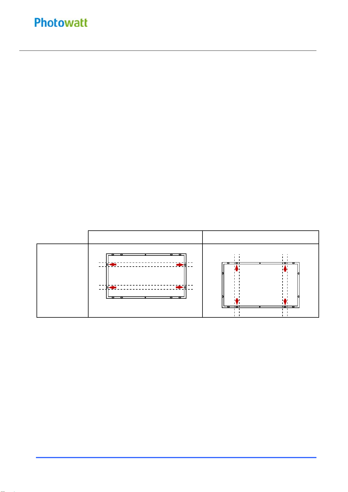
Clamp positions are of crucial importance for the reliability of the installation, the clamp centerlines must
only be positioned as indicated in table 2, depending on the configuration and load.
For the BIPV modules, please follow the specific Installation Manual.
5.2 MODULE WIRING
Correct wiring scheme
When designing the system, avoid forming loops (to minimize risk in the event of an indirect lighting
strike). Make sure that wiring is correct before starting up the system. If the measured open circuit voltage
(Voc) and short-circuit current (Isc) differ from the specifications, then there is a wiring fault.
Correct connection of plug connectors
Make sure that the connection is safe and tight. The plug connector should not receive outer stress. The
connector should only be used to connect the circuit. It should never be used to turn the circuit on and off.
Use of suitable materials
Use special solar cable and suitable plugs only (wiring should be placed in conduit that is sunlight-resistant
if exposed) in accordance with local fire, building and electrical codes. Ensure that they are in perfect
electrical and mechanical condition.
The permitted type of solar cable is single conductor, 2.5-10 mm2(8-14 AWG), 90°C wet rated, with proper
insulation to withstand the maximum possible system open-circuit voltage (such as TUV 2PfG1169
approved). The conductor material should be copper only. Select a suitable conductor gauge to minimize
voltage drop.
Cable protection
Secure the cables to the mounting system using UV-resistant cable ties. Protect exposed cables from damage
with appropriate precautions (e.g. locate them within plastic conduit).Avoid exposure to the direct sunlight.
6.0 MAINTENANCE
Regular maintenance is required to keep modules clear of snow, bird droppings, seeds, pollen, leaves,
branches, dirt spots and dust.
When there is a noticeable buildup of soiling deposits on the module surface, wash the PV array with water
and a gentle cleaning implement (a sponge) during the cool part of the day. Dirt must never be scraped or
rubbed away when dry, as this will cause micro-scratches.
Do not use high pressure cleaning systems on modules
If snow is present, a brush with soft bristles can be used to clean the surface of the module.
Periodically inspect the system to make sure all wiring and supports stay intact.
If you need electrical or mechanical inspection or maintenance, it is recommended to have a licensed,
authorized professional carry out the job to avoid hazards of electric shock or injury.
Do not change the PV components (diode, junction box, plug connectors). Doing so will void the warranty.
9

EDF ENR PWT
D06‐P06‐01Indice1Date:3‐01‐13
EDFENRPWT
Sociétéparactionssimplifiéeàassociéunique–aucapitalde37505000€‐N°513281972RCSNANTERRE
Siègesocial:100EsplanadeduGénéraldeGaulle–CœurDéfense–TourB92932ParisLaDéfensecedex.
33,RueSaintHonoré‐Z.I.Champfleuri
38300BourgoinJallieu‐France
Tel:0474938020‐Fax:0474938040
ANNEX: MECHANICAL AND ELECTRICAL RATINGS
Standard Test Conditions are: irradiance of 1 kW/m2, AM1.5 spectrum, and cell temperature of 25°C. Pmax of
any individual module will be within [0; +5W] of these specified values. Specifications are subject to change
without notice.
Table 3: Specifications for PW-series photovoltaic modules under STC
PW2350
PW2300
Measuring uncertainty 5%, including 2.5% uncertainty on the reference module tested by a certified international laboratory
10
Table of contents
Other PHOTOWATT Solar Panel manuals
Popular Solar Panel manuals by other brands

First Solar
First Solar 6 Plus Series user guide

Sonnenkraft
Sonnenkraft SKR500 Series manual

Nature Power
Nature Power 55120 user manual

Sharp
Sharp NB-JD540 installation manual

Panasonic
Panasonic HIT Double Photovoltaic modules General installation manual

ALTA
ALTA Bliss Automation Installation and reference guide