NKE SAMBAT User manual

nke Tel 02-97-36-41-31 Fax 02-97-36-55-17 http://www.nke-instrumentation.com
PAGE 1/43
USER MANUAL
SAMBAT
Vers 3
Référence du / Document reference : SAMBAT-60-07-456_UTI_UK.doc
Document applicable to the product(s): SAMBAT station and profiler

nke Tel 02-97-36-41-31 Fax 02-97-36-55-17 http://www.nke-instrumentation.com
PAGE 2/43
CONTENTS
1. INTRODUCTION................................................................................................................................................................4
2. PHOTOS...............................................................................................................................................................................5
2.1 GPS/GPRS AERIAL ........................................................................................................................................................6
3. CHARACTERISTICS OF MEASUREMENT..................................................................................................................7
3.1 DEPTH (CHANNEL 0).......................................................................................................................................................7
3.2 TEMPERATURE (CHANNEL 1) ..........................................................................................................................................7
3.3 CONDUCTIVITY (CHANNEL 2) .........................................................................................................................................7
3.4 TURBIDITY (CHANNEL 3) ................................................................................................................................................7
3.5 DISSOLVED OXYGEN (CHANNEL 4) .................................................................................................................................8
3.5.1 Choix de la mesure...........................................................................................................................................8
3.5.2 Oxygen saturation measurement setting...........................................................................................................8
3.5.3 Oxygen concentration measurement setting.....................................................................................................9
3.5.4 Oxygen sensor temperature measurement setting ............................................................................................9
3.5.5 Concentration...................................................................................................................................................9
3.6 PH (CHANNEL 5)...........................................................................................................................................................10
3.7 FLUORESCENCE (CHLOROPHYLL A OR PHYCOCYANINE)(CHANNEL 6).........................................................................10
3.7.1 Chlorophylle...................................................................................................................................................10
3.7.2 (PHYCOCIANINE).........................................................................................................................................10
3.8 BATTERY VOLTAGE (CHANNEL 5, 6OR 7) (AS PER CONFIGURATION)............................................................................11
4. OPERATION......................................................................................................................................................................12
4.1 START/STOP MODES................................................................................................................................................12
4.2 MEASUREMENT CYCLE AND GPRS TRANSMISSION.............................................................................................12
4.3 RADIO ...........................................................................................................................................................................13
4.4 GPS ..............................................................................................................................................................................13
4.5 BRUSH...........................................................................................................................................................................13
4.6 SAMBAT “GPRS” TAB ..............................................................................................................................................14
4.6.1 GPRS..............................................................................................................................................................14
4.7SAMBAT “ALARMS” TAB........................................................................................................................................15
4.7.1 Alarms allocated to channels .........................................................................................................................15
4.7.2 Brush alarms ..................................................................................................................................................16
4.7.3 GPS alarms.....................................................................................................................................................16
5. CONFIGURATION PROCEDURE FOR A SAMBAT PROBE...................................................................................17
6. BRUSH FUNCTION..........................................................................................................................................................20
6.1 THE BRUSH: START..................................................................................................................................................21
6.2 THE BRUSH: BRUSH ALARM DETECTION...........................................................................................................21
6.2.1 The various types of alarms............................................................................................................................21
6.2.2 Replacing the brush........................................................................................................................................22
7. GPS OPERATION.............................................................................................................................................................23
7.1 MANAGEMENT OF ALARMS AND CONSIDERATION OF TIDAL RANGE............................................................23
7.2 GPS INSTALLATION PRECAUTIONS.....................................................................................................................23
8. FILE FORMATS................................................................................................................................................................25
8.1 MEASUREMENT FILES....................................................................................................................................................25
8.1.1 Example of a MEASUREMENT file: SAMBAT_mesures_50000_020913112341.txt.....................................26
8.2 ALARMS FILE ................................................................................................................................................................27
8.3 BRUSH ALARMS FILE .....................................................................................................................................................28
8.4 GPS POSITION FILE........................................................................................................................................................28
8.4.1 Example of a GPS log file: gps_SAMBAT_50000_020913145451.txt ...........................................................29
8.4.2 GPS alarm file................................................................................................................................................29
9. ADJUSTMENT & MAINTENANCE PROCEDURES ..................................................................................................30
9.1 PRESSURE SENSOR.........................................................................................................................................................30
9.1.1 Depth zero drift correction.............................................................................................................................30
9.2 CONDUCTIVITY /TEMPERATURE SENSOR ......................................................................................................................31
9.2.1 Storage:..........................................................................................................................................................31
9.2.2 Cleaning the sensor back from the field before calibration ...........................................................................32

nke Tel 02-97-36-41-31 Fax 02-97-36-55-17 http://www.nke-instrumentation.com
PAGE 3/43
9.2.3 Routine cleaning.............................................................................................................................................32
9.2.4 Adjustment Temperature ................................................................................................................................32
9.2.5 Adjustment conductivity..................................................................................................................................33
9.3 CAPTEUR CYCLOPS 7TURNER DESIGNS (TBD,FLUO &PHYCOCYANINE)..................................................................34
9.3.1 Adjustment using standard solutions..............................................................................................................35
9.3.2 Procedure.......................................................................................................................................................35
9.3.3 In situ adjustment ...........................................................................................................................................37
9.4 OXYGEN SENSOR.....................................................................................................................................................38
9.4.1 Cleaning .........................................................................................................................................................38
9.1 PH SENSOR.................................................................................................................................................................39
9.1.1 Maintenance...................................................................................................................................................39
9.1.1 Storage ...........................................................................................................................................................39
9.1.2 Calibration .....................................................................................................................................................39
10. CHARACTERISTICS ...................................................................................................................................................40
10.1 CARACTERISTIQUES FONCTIONNELLES ..................................................................................................................40
10.2 MECHANICAL CHARACTERISTICS ......................................................................................................................40
10.3 RADIO LINK SPECIFICATIONS...............................................................................................................................40
10.4 MEMORY AUTONOMY............................................................................................................................................40
10.5 ENERGY AUTONOMY..............................................................................................................................................40
10.5.1 SAMBAT C/T/D/TBD/DO...............................................................................................................................40
10.5.2 Influence of GPS on consumption ..................................................................................................................41
11. REPLACING THE BATTERY PACKS......................................................................................................................42
12. ANNEX 1: GPS/GPRS AERIAL COAXIAL CONNECTOR....................................................................................43
13. END OF LIFE.................................................................................................................................................................43

nke Tel 02-97-36-41-31 Fax 02-97-36-55-17 http://www.nke-instrumentation.com
PAGE 4/43
1. INTRODUCTION
The SAMBAT is an autonomous multiparameter probe with brush and
teletransmission.
It is used to measure the main physical parameters of water (i.e. temperature, depth,
conductivity, turbidity, fluorescence, dissolved oxygen and pH) over a period of up to
several months.
This device uses a brush to protect the fluorescence and turbidity sensors from
biofouling.
The data measured can be transmitted by email using the integrated GPRS Modem.
The SAMBAT is configured using the Winmemo II software via a radio link (Data
Pencil Radio) with a range of several tens of meters.
The SAMBAT has been designed to be mounted on any type of support (very light
buoy, post, pontoon, etc.).

nke Tel 02-97-36-41-31 Fax 02-97-36-55-17 http://www.nke-instrumentation.com
PAGE 5/43
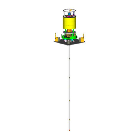
2. PHOTOS
Battery compartment
Aerial connector
Electronic compartment
Sensors & Brush housing
Maintenance zone
Brush body

nke Tel 02-97-36-41-31 Fax 02-97-36-55-17 http://www.nke.fr
PAGE 7/43
3. CHARACTERISTICS OF MEASUREMENT
3.1 DEPTH (CHANNEL 0)
Unit: For the calculation of salinity, the calibration values of the channel 0 must represent the physical values of
the depth or the pressure expressed in meters or dbar.
Sensor:Piezoresistive pressure sensor
Measurement range: 0 to 10 m
Accuracy: < 0.3% of full range, being 0,03 m.
Resolution: < 0.00025 m
Measurement range: 0 to 30 m
Accuracy: < 0.5% of full range, being 0,15 m.
Resolution: < 0.00075 m
Measurement range: 0 to 50 m
Accuracy: < 0.8% of full range, being 0,40 m.
Resolution: < 0.00125 m
Note that the calibration of the pressure channel is performed at the average atmospheric pressure 1 013 mbar (or
760 mm Hg)
3.2 TEMPERATURE (CHANNEL 1)
Sensor: thermistor
Measurement range: -5°C/+35°C.
Maximum resolution: 0.5m°C at 0°C, 1m°C at 10°C, 1.5m°C at 20°C, 3m°C at 35°C
Accuracy: < 50m°C in the 0°C/25°C range.
Response time: < 2s at 63%
3.3 CONDUCTIVITY (CHANNEL 2)
Unit The text of the field Unit of the channel 2 is only configured for informational purposes and is not taken into
account when calculating the physical value (Example: mS).
Response time: < 0.5s
Range: The conductivity measurement range can be configured, in the factory, to one of the 3 ranges below:
Measurement range (mS/cm)
Resolution (µS/cm)
Accuracy (µS/com)
0 –70
< 1.2
< 50
0 –2
< 0.04
< 20
3.4 SALINITY
Unit: The text of the field Unit of the channel 2 is only configured for informational purposes and is not taken into
account when calculating the physical value (Example: g / l or PSU).
Measurement range (PSU)
Resolution (PSU)
Accuracy (PSU)
2 –42
< 0.001
< 0.1
3.5 TURBIDITY (CHANNEL 3)

nke Tel 02-97-36-41-31 Fax 02-97-36-55-17 http://www.nke.fr
PAGE 8/43
Sensor: Turner Designs CYCLOPS-7 (See product datasheet in the annex)
Wavelength: IR (850 nm)
Range: the turbidity measurement range can be configured, in the factory, to one of the 3 ranges below:
Measurement range:
Resolution:
Linearity
0 –30
0.0015 ntu
0.99 r2
0 –300
0.015 ntu
0 –1000 (up to 3000 ntu)
0.05 ntu
The measurement of turbidity sensor is linear from 0 to 1000 NTU (Linearity 0.99 R²).
She gets up to 3000 ntu (2nd order polynomial).
The probe is adjusted from solutions Formazine. These standard solutions are prepared not volumetric
dilution of a stock solution of 4000 ntu with deionized water.
MES custom websites, regardless of the turbidity values is essential to try to establish a correlation
between "suspended solids in the water" (MES) and the value of Turbidity (NTU) probes SMATCH
3.6 DISSOLVED OXYGEN (CHANNEL 4)
Sensor: ODO PONSEL (freshwater) _ Optical measurement by luminescence.
(See product datasheet in the annex)
Response time: NC
Water movement: no circulation necessary
Maximum pressure : 5 bar
3.6.1 Choix de la mesure
The channel using the Channel 4 allows to record the value of Saturation or oxygen Concentration in fresh
water.
The choice measure is made by the selection of the sensor type "Oxygen Saturation" or "Oxygen
Concentration" of Channel 4, in the "Channels" of the configuration settings tab
The sensor of oxygen used in the SAMBAT integrates its own adjustment coefficients.
3.6.2 Oxygen saturation measurement setting
In order to take dissolved oxygen saturation measurements, the sensor type and the calibration coefficient in the
oxygen channel must be configured as follows:

nke Tel 02-97-36-41-31 Fax 02-97-36-55-17 http://www.nke.fr
PAGE 9/43
3.6.3 Oxygen concentration measurement setting
In order to take dissolved oxygen concentration measurements, the sensor type and the calibration coefficient in
the oxygen channel must be configured as follows:
3.6.4 Oxygen sensor temperature measurement setting
In order to take temperature measurements using the oxygen sensor, the sensor type and the calibration
coefficient in the oxygen channel must be configured as follows:
3.6.5 Concentration
Measurement range: 0 to 20 mg/l.
Resolution: 0,01%.
Accuracy: +/- 0.1 mg/L
3.6.5.1 Saturation
Measurement range: 0 to 200%.
Resolution: 0,01%.
Accuracy: +/- 1%

nke Tel 02-97-36-41-31 Fax 02-97-36-55-17 http://www.nke.fr
PAGE 10/43
3.7 PH (CHANNEL 5)
Sensor: PONSEL PHEHT.
Measurement range: 0 to 14 pH (insensitive to Na+ ions up to pH 13)
Resolution: 0.0003 pH
Accuracy: ± 0.1 pH
Maximum pressure : 5 bar
3.8 FLUORESCENCE (CHLOROPHYLL A OR PHYCOCYANINE) (CHANNEL 6)
Fluorescence is the phenomenon whereby some compounds absorb certain wavelengths of light and, almost
instantaneously, they emit a light of a different wavelength.
This type of sensor is not factory set.
A voltage adjustment of the measuring stage is carried out in accordance with the sensor manufacturer's
specifications (range 0-5 volts).
If you wish to calibrate the probe for the measurement of "chlorophyll a", it becomes necessary to go through a
phase of algal culture (using the same species you are likely to encounter in your environment).
3.8.1 Chlorophyll A sensor
Chlorophyll a naturally absorbs blue light and emits a red light.
This Turner designs –CYCLOPS 7 sensor detects chlorophyll a by transmitting an excitation beam of light in
the 460 nm range (blue) and detects the light emitted by the sample in the 680 nm range (red).
3.8.2 Chlorophyll
Sensor: Turner Designs CYCLOPS-7
Excitation wavelength: 460 nm
Emission wavelength: 620-715 nm
Detection wavelength: 300-1100 nm
Range: Chlorophyll a; factory set to one of the 3 ranges below:
Measurement range
(µgL)range:
Resolution (µgL)
Linearity
0 –500
< 0.008
0.99 r2
0 –50
< 0.0008
0 –5
< 0.00008
3.8.3 PHYCOCIANIN
Sensor: Turner Designs - CYCLOPS-7
Excitation wavelength: 595 nm
Emission wavelength: 670 nm
Detection wavelength: 300-1100 nm
Range: phycocyanin; factory set to one of the 3 ranges below:
Measurement range (Cml)
Resolution (Cml)
Linearity
0 - 2 000 000 cellules /mL
< 31
0.99 r2
0 –200 000 cellules /mL
< 3
0 –20 000 cellules /mL
< 0.3
A "Solid Secondary Standard" can be purchased as an option to check the stability over time.

nke Tel 02-97-36-41-31 Fax 02-97-36-55-17 http://www.nke.fr
PAGE 11/43
3.9 BATTERY VOLTAGE (CHANNEL 5, 6 OR 7) (AS PER CONFIGURATION)
This channel is used to measure the supply voltage of the SAMBAT (internal battery pack).
Measurement range: 0 to 18 V.
Accuracy: 50 mV
Internal battery pack voltage –typical: 10.8V
Internal battery pack voltage –minimum: 9V

nke Tel 02-97-36-41-31 Fax 02-97-36-55-17 http://www.nke.fr
PAGE 12/43
4. OPERATION
The SAMBAT can be configured and read using the Winmemo II software via radio link, using a Data Pencil
Radio, connected via USB to a computer.
All command functions are available in the Winmemo II software.
You can only communicate with the SAMBAT when it is out of the water.
When changing the settings using the Winmemo II software, use the SAMBAT tab to change specific
parameters.
They must only be changed by a Technician or Expert user of Winmemo II.
4.1 START/STOP MODES
Only the following start/stop modes can be used:
- Manual start and stop
- Condition start and manual stop
- Date start and manual stop
Other start/stop modes must not be used or you risk malfunction of the SAMBAT.
4.2 MEASUREMENT CYCLE AND GPRS TRANSMISSION
Whatever the start/stop mode used, GPRS transmission always stops the measurement cycle in progress.
When the GPRS transmission is complete, the measurement cycle is restarted as when it was started by the
Winmemo II software.
As a result, when the “Condition start and manual stop”mode is used, each time the measurement cycle is
restarted after a GPRS transmission, the start condition is verified again.
If the condition is no longer fulfilled, the SAMBAT remains on standby on “condition start”until the condition is
again true.

nke Tel 02-97-36-41-31 Fax 02-97-36-55-17 http://www.nke.fr
PAGE 13/43
4.3 RADIO
Recorder address: setting specifying the radio address of the SAMBAT (unique address set in the
factory).The Data-Pencil Radio uses this address to communicate with the probe.
4.4 GPS
The SAMBAT is equipped with GPS location function. This function is used to record the GPS position of the
probe regularly in a file, and depending on the settings defined in WINMEMO II, to generate an alarm if the
SAMBAT detects a drift in position. Several operating modes can be configured by the user:
- No GPS management
- Management of the GPS LOG function without Alarm
- Management of the GPS LOG function with Alarm
Measurement rate: defines the interval between two GPS position readings. The interval is expressed in
hours in increments of one hour. For a measurement rate of 6 hours, the SAMBAT will take a GPS reading
every 6 hours. If the rate is set to 0, the GPS function is deactivated.
It is recommended to set the measurement rate to a minimum of 6 hours.
For more details of GPS operation, see chapter 7 GPS OPERATION on page 23.
4.5 BRUSH
Brush activated: selecting this setting activates automatic management of the Brush, according to the
defined brush rate.
Period: setting specifying the rotation frequency of the Brush. The brush can be set from 1 hour (min.) to 24
hours (max.) in increments of 1 hour. For example, for a speed of 4 hours, the probe brush will rotate every 4
hours. If the rate is set to 0, the brush function is deactivated.
Angle: factory setting only accessible in Expert mode. It is used to define the brush stroke needed to brush
the defined sensors.

nke Tel 02-97-36-41-31 Fax 02-97-36-55-17 http://www.nke.fr
PAGE 14/43
For more details of brush operation, see the chapter Brush Function on page 20.
4.6 SAMBAT “GPRS” TAB
4.6.1 GPRS
Maximum depth for GPRS emission: GPRS communication does not operate when the connected aerial is
immersed.
This parameter sets the immersion depth below which the SAMBAT will no longer attempt to transmit
measurements or alarms by email. This setting should be left at 0 if the SAMBAT is mounted on a buoy (with
the GPRS aerial always above water).
Number of data transfers per day: parameter specifying the number of email transfers of measurements
recorded in the SAMBAT. This setting must be set to 0 if the SAMBAT should not send email (use as an
autonomous recorder).
Management station email address: the email address where all data will be sent. The address must not
exceed 32 characters.
- The other parameters should not be changed and are factory set according to the telephone subscription
and SIM card (outlined in red).

nke Tel 02-97-36-41-31 Fax 02-97-36-55-17 http://www.nke.fr
PAGE 15/43
4.7 SAMBAT “ALARMS” TAB
4.7.1 Alarms allocated to channels
- An alarm file can be generated and transferred by email when a minimum and/or maximum threshold is
reached. To set the alarm, check the Minimum or Maximum box to be able to enter the minimum or
maximum value in the box to trigger the alarm.
- The threshold can be set in Winmemo II for each measurement channel.
- A minimum time of 6 hours elapses between each transfer of alarm files whatever the alarm detection
interval. (Only if the “real-time alarm" function is not activated).
- Thus, if an alarm is detected less than 6 hours after the last alarm file was sent, it will be recorded in the file
for transmission after the 6 hour period. The alarm files are also sent when the measurement files are
transferred according to the setting "Number of data transfers per day”.

nke Tel 02-97-36-41-31 Fax 02-97-36-55-17 http://www.nke.fr
PAGE 16/43
- Real-time alarm: setting forcing the emission of alarms allocated to channels in real time. The threshold can
be set from 1 hour to 6 hours.
Whenever an alarm is detected when a threshold on one of the measurement channels is exceeded, an
alarm file is sent immediately. After that, if the alarm reoccurs, it is sent after the time defined (from 1 to 6
hours).
Example: if an alarm is detected on the turbidity channel at a threshold > 500NTU and an interval of 1 hour.
If an alarm is detected on this channel, it is recorded in the alarm file and transferred immediately. If the
turbidity value remains the same, a second alarm file will be transferred during the following hour and so on
until the turbidity value returns to normal.
4.7.2 Brush alarms
Brush alarms: if this parameter is selected, it activates monitoring of the brush function. Thus, any blocking
of the brush or rotation problem generates an alarm file.
- Block alarm
- Force alarm
The created alarm file is sent when the measurement files are transferred according to the setting "Number
of data transfers per day”.
4.7.3 GPS alarms
Turning circle alarm: The turning circle alarm can be activated when the GPS function is active (the
measurement rate setting is not 0). If the SAMBAT exceeds this turning circle (expressed in meters from its
initial position), a GPS alarm will be generated.
For more details about GPS alarm management, see the chapter on “Management of alarms and tidal
range considerations”.

nke Tel 02-97-36-41-31 Fax 02-97-36-55-17 http://www.nke.fr
PAGE 17/43
5. CONFIGURATION PROCEDURE FOR A SAMBAT PROBE
In this chapter, we will explain the procedure for correctly configuring the SAMBAT probe for several
months of deployment.
- Connect the probe using Winmemo II and select EXPERT mode.
- Download the measurement files still present in the probe’s memory.
Caution - If you change the measurement rate, all measurements in the memory will be erased and
lost.
- Read the configuration using the command Read.
-
- Edit the configuration by double clicking on the file shown in the arborescence.
- Complete the comment text field in the Product tab.
For example, this may describe the probe’s measurement location. This text appears in the header of
the measurement file (see chapter Measurement file on page 25)
-
- In the “Cycles” tab, enter the measurement rate for the probe for all channels.
In the example below, the probe will take a measurement every 15 minutes from start-up until the probe
is stopped by the user.
-

nke Tel 02-97-36-41-31 Fax 02-97-36-55-17 http://www.nke.fr
PAGE 18/43
- Activate GPS mode and Brush operation in the SAMBAT / General tab.
- Enter the number of file transfers per day and check that the recipient email address is correct.
- Select whether or not to activate the various alarms.
- Select the button to confirm any modifications made to the configuration.

nke Tel 02-97-36-41-31 Fax 02-97-36-55-17 http://www.nke.fr
PAGE 19/43
- Select the edited configuration file and transfer it to the probe using the command button Upload
configuration.
This command is used to update the probe with the modifications made.
- Check the time and date on the probe by selecting the Update time button.
If necessary, synchronise the probe’s clock with that of the PC using the Synchronize button.
Once all these steps are complete, the probe needs to be set to record.
- Open the Manage probe status window by clicking on the Status button.
- Click on the button to Start the probe
- After the memory has been erased, the probe switches to record mode.
- Close the window and disconnect the probe.

nke Tel 02-97-36-41-31 Fax 02-97-36-55-17 http://www.nke.fr
PAGE 20/43
6. BRUSH FUNCTION
The brush function integrated in the SAMBAT probe is designed to reduce the presence of dirt and bio-fouling
during prolonged deployments.
By regularly using soft brushing, the SAMBAT brush keeps the sensor detection windows clean (optical
window).
It can be used on the turbidity, fluorescence, phycocianine and oxygen sensors.
The brush rotates clockwise.
Advantage:
- Helps maintain coherent measurements by reducing biofouling
- Automatic brush management depending on the measurement (if measurement within 30s, brush
delayed)
- The brush maintains its settings when the battery is changed
- Brush functions according to the sensors installed (angle setting)
- Backward and forward movement
- Brush park position
- Replacement brushes available
The brush function is factory set and depends on the number and type of sensors installed.
The angle field in the SAMBAT configuration tab (see SAMBAT General tab) indicates the brushing angle to
be used on the required sensors.
This configuration prevents brushing of the wrong sensor or stopping the brush on a longer sensor.
To ensure correct operation of the brush, it is fitted with several diagnostic tools:
- Self-calibration of its position (no calibration required)
- Once a day the system calibrates itself with a learning cycle
- If a blockage occurs, a self-calibration positioning cycle will be done on the next brush cycle
- If a blockage occurs, the self-calibration cycle is done clockwise.
Table of contents
Other NKE Measuring Instrument manuals
Popular Measuring Instrument manuals by other brands
National Instruments
National Instruments PXIe-5774 Getting started guide
RigExpert
RigExpert AA-230 ZOOM Software manual
IS Technologies
IS Technologies SONDAR 5000 user manual

Konica Minolta
Konica Minolta MULTI GLOSS 268 instruction manual
PKP
PKP DS04.1 instruction manual
Keysight Technologies
Keysight Technologies X Series manual

