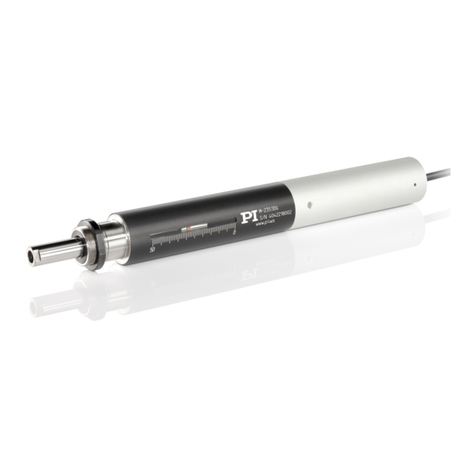
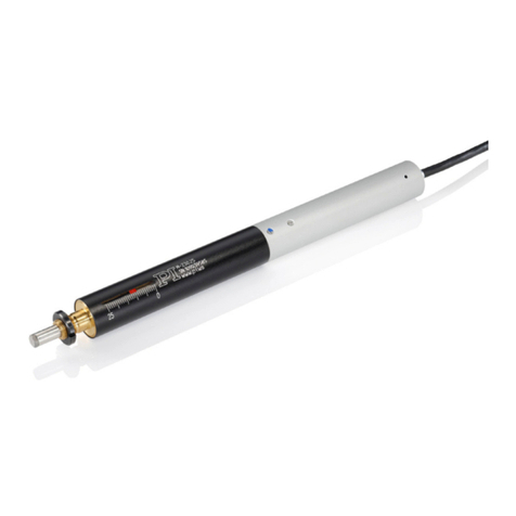
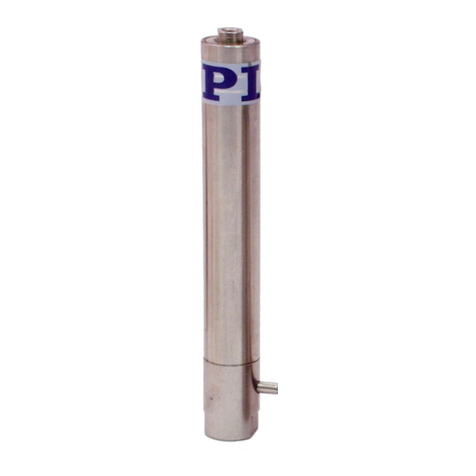
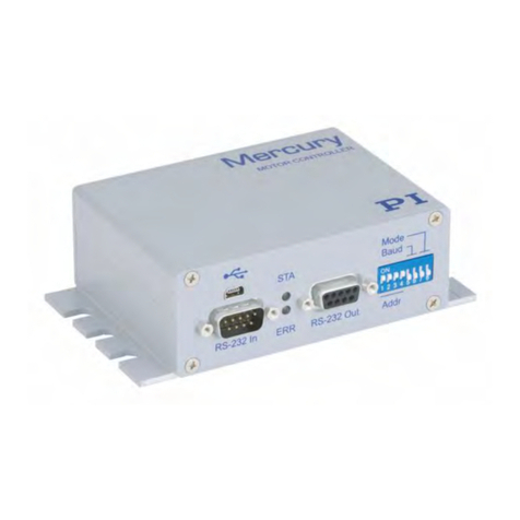
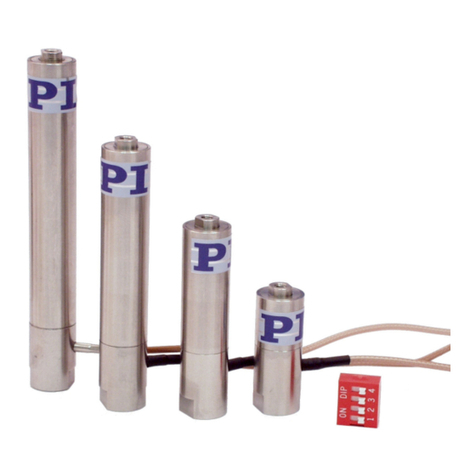
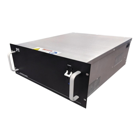
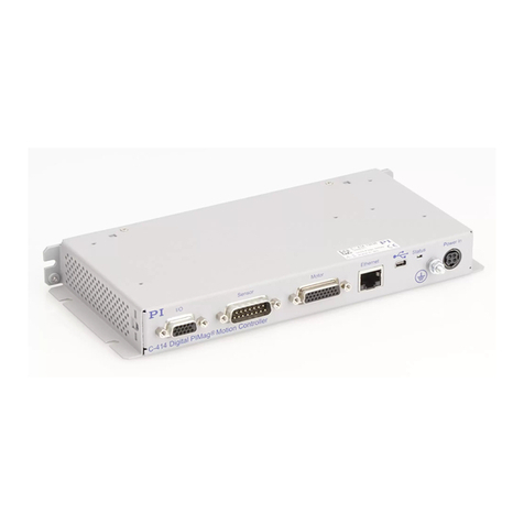
PI V-273 VC User manual

Physik Instrumente (PI) GmbH & Co. KG, Auf der Roemerstrasse 1, 76228 Karlsruhe, Germany
Phone +49 721 4846-0, Fax +49 721 4846-1019, Email info@pi.ws, www.pi.ws
MP155E
V
-273 VC Linear Actuator
User Manual
Version: 1.1.4
Date: 22.06.2020
This document describes the following products:
V-273.440
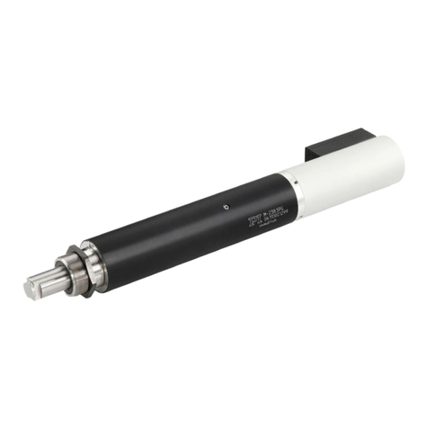
PIMag® voice coil linear actuator, 20 mm, 6 N,
linear encoder, 0.01 µm resolution
V-273.441
PIMag® voice coil linear actuator, 20 mm, 6 N,
linear encoder, 0.01 µm resolution, force
sensor

The following company names and brands are registered trademarks of Physik Instrumente (PI) GmbH & Co.
KG:
PI®, NanoCube®, PICMA®, PILine®, NEXLINE®, PiezoWalk®, NEXACT®, Picoactuator®, PInano®, PIMag®,
Q-Motion®
Notes on brand names and third-party trademarks:
BiSS is a registered trademark of iC-Haus GmbH.
The patents held by PI are found in our patent list: https://www.physikinstrumente.com/en/about-pi/patents
© 2020 Physik Instrumente (PI) GmbH & Co. KG, Karlsruhe, Germany. The text, photographs, and drawings in
this manual are protected by copyright. With regard thereto, Physik Instrumente (PI) GmbH & Co. KG retains
all the rights. The use of any text, images and drawings is permitted only in part and only when indicating the
source.
Original instructions
First printing: 22.06.2020
Document number: MP155E, KSch, Version 1.1.4
Subject to change. This manual is superseded by any new release. The latest respective release is available for
download (p. 3) on our website.

1About this Document 1
1.1 Objective and Target Audience of this User Manual.................................................. 1
1.2 Symbols and Typographic Conventions...................................................................... 1
1.3 Definition of Terms..................................................................................................... 2
1.4 Figures ........................................................................................................................ 3
1.5 Other Applicable Documents ..................................................................................... 3
1.6 Downloading Manuals................................................................................................ 3
2Safety 5
2.1 Intended Use .............................................................................................................. 5
2.2 General Safety Instructions ........................................................................................ 5
2.3 Organizational Measures............................................................................................ 5
3Product Description 7
3.1 Model Overview ......................................................................................................... 7
3.2 Product View .............................................................................................................. 7
3.2.1 Overview........................................................................................................ 7
3.2.2 Product Details .............................................................................................. 8
3.2.3 Product Labeling.......................................................................................... 10
3.3 Scope of Delivery...................................................................................................... 11
3.4 Suitable Controllers .................................................................................................. 11
3.5 Technical Features.................................................................................................... 12
3.5.1 Linear Encoder............................................................................................. 12
3.5.2 Reference Switch......................................................................................... 12
3.5.3 Force Sensor ................................................................................................ 12
3.5.4 Adapter with ID Chip for Connecting to the C-413.2xx Controller.............. 12
3.5.5 Guiding......................................................................................................... 13
4Unpacking 15
5Installation 17
5.1 General Notes on Installation................................................................................... 17
5.2 Optional: Changing the Contact Part of the Force Sensor on the V-273.441 .......... 19
5.3 Installing the V-273 into a Mechanical Mounting .................................................... 20
5.4 Connecting the V-273 to the Controller................................................................... 23
Contents

6Startup and Operation 25
6.1 General Notes on Startup and Operation ................................................................ 25
6.2 Temperature Dependency of the Nominal Current: Calculating the Nominal
Current...................................................................................................................... 28
6.3 Starting Up the V-273 with the C-413 Controller..................................................... 29
7Maintenance 31
7.1 General Notes on Maintenance ............................................................................... 31
7.2 Preparing the V-273 for Transport ........................................................................... 31
7.3 Cleaning the V-273 ................................................................................................... 32
8Troubleshooting 33
9Customer Service 35
10 Technical Data 37
10.1 Specifications............................................................................................................ 37
10.1.1 Data Table.................................................................................................... 37
10.1.2 Maximum Ratings........................................................................................ 38
10.1.3 Ambient Conditions and Classifications ...................................................... 39
10.1.4 Reference Switch Specifications.................................................................. 39
10.2 Dimensions ............................................................................................................... 40
10.2.1 V-273.440 .................................................................................................... 40
10.2.2 V-273.441 .................................................................................................... 41
10.3 Pin Assignment ......................................................................................................... 43
10.3.1 Motor and Position Sensor Connector ........................................................ 43
10.3.2 V901B0030 Adapter..................................................................................... 43
10.3.3 V-273.441: Force Sensor Connector............................................................ 45
11 Old Equipment Disposal 47
12 EU Declaration of Conformity 49

1 About this Document
V-273 VC Linear Actuator MP155E Version: 1.1.4 1
In this Chapter
Objective and Target Audience of this User Manual ..................................................................... 1
Symbols and Typographic Conventions ......................................................................................... 1
Definition of Terms ........................................................................................................................ 2
Figures............................................................................................................................................ 3
Other Applicable Documents......................................................................................................... 3
Downloading Manuals ................................................................................................................... 3
1.1 Objective and Target Audience of this User Manual
This manual contains information on using the V-273 as intended.
It assumes that the reader has a fundamental understanding of basic servo systems as well as
motion control concepts and applicable safety procedures.
The latest versions of the user manuals are available for download (p. 3) on our website.
1.2 Symbols and Typographic Conventions
The following symbols and typographic conventions are used in this user manual:
DANGER
Immediate threat of danger
Failure to comply could lead to death or serious injury.
Measures for avoiding the risk.
CAUTION
Dangerous situation
Failure to comply could lead to minor injury.
Precautionary measures for avoiding the risk.
1
About this Document

1 About this Document
2 Version: 1.1.4 MP155E V-273 VC Linear Actuator
NOTICE
Dangerous situation
Failure to comply could cause damage to equipment.
Precautionary measures for avoiding the risk.
INFORMATION
Information for easier handling, tricks, tips, etc.
Symbol/
Label
Meaning
1.
2.
Action consisting of several steps with strict sequential
order
Action consisting of one or more steps without relevant
sequential order
Lists
p. 5
Cross-reference to page 5
RS-232
Label on the product indicating an operating element
(example: RS-232 interface socket)
Warning signs attached to the product referring to
detailed information in this manual.
1.3 Definition of Terms
Term Explanation
VC linear actuator /
VC linear drive
VC = Voice Coil
The feed is generated by the Lorentz force on an energized
coil (PIMag® principle) that couples to a runner. The V-273
thus combines a relatively long travel range with a high
velocity and a high resolution.
Max. push/pull
force
Maximum force in the direction of motion.
Position or velocity control:
When a counterforce is exerted on the linear actuator, the
linear actuator counteracts it with maximum force to
maintain the target position or target velocity. When the
counterforce exceeds the specified value of the push/pull
force (p. 37), displacements or changes in velocity can occur.

1 About this Document
V-273 VC Linear Actuator MP155E Version: 1.1.4 3
Term Explanation
Max. push/pull
force
Force control:
When a counterforce is exerted on the linear actuator, the
linear actuator maximally counteracts it with the target force
value. If the counterforce exceeds the target force value,
displacements are possible.
When the servo mode is switched off, the weight force of the
moving mass can be compensated for by an AutoZero
procedure (see user manual of the C-413 controller).
Incremental position
sensor
Sensor (encoder) for detecting changes of position or changes
of angle. Signals from the incremental position sensor are
used for axis position feedback. After the controller is
switched on, referencing must be done before absolute
target positions can be commanded and reached.
1.4 Figures
For better understandability, the colors, proportions, and degree of detail in illustrations can
deviate from the actual circumstances. Photographic illustrations may also differ and must not
be seen as guaranteed properties.
1.5 Other Applicable Documents
The devices and software tools from PI mentioned in this documentation are described in
separate manuals.
Product
Document
C-413 PIMag® Controller
MS224E User Manual
PIMikroMove
SM148E Software Manual
1.6 Downloading Manuals
INFORMATION
If a manual is missing or problems occur with downloading:
Contact our customer service department (p. 35).
Downloading manuals
1. Open the website www.pi.ws.
2. Search the website for the product number (e.g., P-882) or the product family (e.g.,
PICMA® bender).

1 About this Document
4 Version: 1.1.4 MP155E V-273 VC Linear Actuator
3. Click the corresponding product to open the product detail page.
4. Click Downloads.
The manuals are shown under Documentation.
5. Click the desired manual and fill out the inquiry form.
The download link will then be sent to the email address entered.

2 Safety
V-273 VC Linear Actuator MP155E Version: 1.1.4 5
In this Chapter
Intended Use.................................................................................................................................. 5
General Safety Instructions............................................................................................................ 5
Organizational Measures ............................................................................................................... 5
2.1 Intended Use
The V-273 is a laboratory device as defined by DIN EN 61010-1. It is intended for indoor use and
use in an environment which is free of dirt, oil, and lubricants.
The V-273 has a VC linear drive (p. 2), a position sensor and, depending on the model, a force
sensor as well. The V-273 is intended for positioning, adjusting and shifting loads in one axis at
various velocities and with defined forces.
The V-273 is a linear actuator for applications in automation or handling technology. The V-273
is not intended for applications in areas in which a failure would present severe risks to human
beings or the environment.
The intended use of the V-273 is only possible when installed and in conjunction with a suitable
controller (p. 11). The controller is not included in the scope of delivery of the V-273.
2.2 General Safety Instructions
The V-273 is built according to state-of-the-art technology and recognized safety standards.
Improper use can result in personal injury and/or damage to the V-273.
Use the V-273 for its intended purpose only, and only when it is in perfect technical
condition.
Read the user manual.
Eliminate any malfunctions that may affect safety immediately.
The operator is responsible for the correct installation and operation of the V-273.
2.3 Organizational Measures
User manual
Keep this user manual with the V-273 always.
The latest versions of the user manuals are available for download (p. 3) on our
website.
2
Safety

2 Safety
6 Version: 1.1.4 MP155E V-273 VC Linear Actuator
Add all information given by the manufacturer to the user manual, for example
supplements or technical notes.
If you give the V-273 to other users, also include this user manual as well as other
relevant information provided by the manufacturer.
Always work according to the complete user manual. If your user manual is incomplete
and is therefore missing important information, damage to equipment can result.
Install and operate the V-273 only after you have read and understood this user
manual.
Personnel qualification
The V-273 may only be installed, started up, operated, maintained, and cleaned by authorized
and appropriately qualified personnel.

3 Product Description
V-273 VC Linear Actuator MP155E Version: 1.1.4 7
In this Chapter
Model Overview............................................................................................................................. 7
Product View.................................................................................................................................. 7
Scope of Delivery ......................................................................................................................... 11
Accessories................................................................................................................................... 11
Suitable Controllers ..................................................................................................................... 11
Technical Features ....................................................................................................................... 12
3.1 Model Overview
Two standard versions of the V-273 linear actuator are available. They differ with regard to the
force sensor and therefore the dimensions.
Model Dimension Force sensor present?
V-273.440
200 mm × 53 mm × 37.2 mm
No
V-273.441
205.5 mm × 53 mm × 37.2 mm
Yes
For further technical data, see the specifications (p. 37).
3.2 Product View
3.2.1 Overview
Figure 1: V-273.440 (left) and V-273.441 (right)
3
Product Description

3 Product Description
8 Version: 1.1.4 MP155E V-273 VC Linear Actuator
3.2.2 Product Details
Figure 2: Front side of the linear actuator, here V-273.440
1Runner (= guide rail)
2Housing
3Connector for motor cable (panel plug, Sub-D 15)
x Positive direction of motion
Figure 3: Front side of the linear actuator, here V-273.441
1Cable exit of the force sensor
2Exchangeable contact part of the force sensor
3Force sensor
4Runner (= guide rail)
5Housing
6Connector for motor cable (panel plug, Sub-D 15)
x Positive direction of motion

3 Product Description
V-273 VC Linear Actuator MP155E Version: 1.1.4 9
Figure 4: V901B0030 adapter for connecting the motor cable
1Connector for motor cable (socket, Sub-D 15)
2Connector for controller (connector, Sub-D 15)
Figure 5: Force sensor
1M3 threaded bolt for screwing the contact part onto the force sensor
Figure 6: Transport safeguard on the side of the linear actuator V-273.44x, hole pattern and the
transport safeguard are identical for the V-273.440 and V-273.441
1Transport safeguard (bracket with 2 M3x8 screws)
2Housing

3 Product Description
10 Version: 1.1.4 MP155E V-273 VC Linear Actuator
3.2.3 Product Labeling
There is a type plate on the housing of the V-273 that contains the following information:
Labeling Description
Data matrix code (example; contains the
serial number)
V-273.440
Product name (example), the characters
following the period refer to the model
116003601
Serial number (example), individual for
each V-273
Meaning of each position (from the left):
1 = internal information,
2 and 3 = year of manufacture,
4 to 9 = consecutive number
Manufacturer's logo
Warning sign "Pay attention to the
manual!"
Warning sign "Magnetic Field"
Prohibition sign for heart pacemakers,
defibrillators, and other active implants
Warning sign "Risk of crushing"
Old equipment disposal (p. 47)
Country of origin:
Germany
Country of origin
WWW.PI.WS
Manufacturer's address (website)
CE conformity mark

3 Product Description
V-273 VC Linear Actuator MP155E Version: 1.1.4 11
V901B0030: Labeling of the D-sub 15 (m/f) adapter
Figure 7: Product labeling of the V901B0030 adapter
1Label with product name of the adapter
2Label with product name and serial number of the actuator for which the adapter is intended
3.3 Scope of Delivery
Item number Component
V-273
Linear actuator according to order (p. 7)
V273E0023
Transport safeguard consisting of:
1 bracket, 9.5 mm x 6 mm
2 screws, A2 M3x8, ISO 4762
V901B0030
D-sub 15 (m/f) adapter for the connection of the motor
cable
MP162EK
Short instructions in printed form
3.4 Suitable Controllers
The V-273 must be connected to a suitable controller. The following controllers from PI are
suitable for operating the V-273:
Controller Description
C-413.20
PIMag® motion controller, 2 channels, OEM board, USB
and SPI interface, force control option
C-413.20A
PIMag® motion controller, 2 channels, OEM board, USB
and SPI interface, analog inputs, force control option
C-413.2G
PIMag® motion controller, 2 channels, benchtop device,
USB and SPI interface, force control option
C-413.2GA
PIMag® motion controller, 2 channels, benchtop device,
USB and SPI interface, analog inputs, force control
option

3 Product Description
12 Version: 1.1.4 MP155E V-273 VC Linear Actuator
PC software is included in the scope of delivery of the controllers from PI. The operation of the
controllers is described in the corresponding user manuals.
Please note that the cable for connecting the V-273 to the electronics must also be ordered
separately.
To order, contact our customer service department (p. 35).
3.5 Technical Features
3.5.1 Linear Encoder
The V-273 is equipped with an optical linear encoder. For the resolution, refer to the table in
the "Specifications" section (p. 37).
Optical linear encoders measure the actual position directly (direct metrology). Therefore,
errors occurring in the drivetrain such as nonlinearity, backlash or elastic deformation, cannot
influence the measurement of the position.
3.5.2 Reference Switch
The V-273 is equipped with a direction-sensing reference switch, which is located at about the
midpoint of the travel range. This sensor transmits a TTL signal that indicates whether the linear
actuator is on the positive or negative side of the reference switch.
See the controller user manual and/or associated software manuals for the commands that
make use of the reference point signal.
For more information, see "Reference Switch Specifications" (p. 39).
3.5.3 Force Sensor
The V-273.441 is equipped with a force sensor. The force sensor is mounted on the runner
(p. 8).
The force sensor allows application of a defined force and measurement of the counterforce
that is applied orthogonally to the contact part of the sensor (p. 20). Forces up to 10 N can be
measured and forces up to 6 N can be applied, each with an open-loop resolution of 1 mN.
The force sensor works as an incremental sensor. When the controller is switched on or
rebooted, the connected force sensor always measures 0 N, regardless of the actual force
exerted on the force sensor.
3.5.4 Adapter with ID Chip for Connecting to the C-413.2xx Controller
The V901B0030 adapter is adapted at the factory to the V-273 to achieve optimum positioning
accuracy.
The adapter has an ID chip on which the following data is stored:
Information on the linear actuator:
−Type
−Serial number

3 Product Description
V-273 VC Linear Actuator MP155E Version: 1.1.4 13
Coefficients of the polynomial for mechanics linearization
Settings for the sensor: E.g. interpolation rate, corrections of hysteresis, phase and
offset, gain values
Data for checking the validity when the contents of the ID chip are read out
When switched on or rebooted, controllers from PI read the data from the ID chip.
For more information on the ID chip recognition, see the manual of the controller used.
INFORMATION
The V901B0030 adapter must not be used if a controller other than a PI controller is to be
used.
In addition, the following conditions must be met by the controller:
It can process differential sin/cos encoder signals.
It has digital inputs for the differential signals of the reference switch of the linear actuator.
It can operate 1-phase DC motors with ±1.5 A.
3.5.5 Guiding
The V-273.44x models are equipped with a recirculating ball bearing. This makes the motion of
the runner insensitive to lateral forces and torques.


4 Unpacking
V-273 VC Linear Actuator MP155E Version: 1.1.4 15
NOTICE
Mechanical overload from incorrect handling!
An impermissible mechanical load on the V-273 due to transportation without a transport
safeguard and incorrect handling, can damage the runner of the V-273 as well as cause loss of
accuracy.
Only ship the V-273 in the original packaging and with the transport safeguard attached.
Only hold the V-273 by the housing
The V-273 is delivered with a transport safeguard attached.
Figure 8: Transport safeguard on the side of the linear actuator V-273.44x, hole pattern and the
transport safeguard are identical for the V-273.440 and V-273.441
1Housing
2Transport safeguard (bracket with 2 M3x8 screws)
Tools and accessories
Hex key AF 2.5
Unpacking the V-273
1. Unpack the V-273 with care.
2. Compare the contents with the items listed in the contract and the packing list. If parts
are incorrectly supplied or missing, contact PI immediately.
3. Inspect the contents for signs of damage. If you notice signs of damage, contact PI
immediately.
4
Unpacking

4 Unpacking
16 Version: 1.1.4 MP155E V-273 VC Linear Actuator
4. Remove the transport safeguard:
a) Loosen and remove both M3 screws.
b) Remove the bracket.
5. Keep all packaging materials and the transport safeguard in case the product needs to
be transported later.
This manual suits for next models
2
Table of contents
Other PI Controllers manuals
Popular Controllers manuals by other brands

Rockwell Automation
Rockwell Automation Allen-Bradley 1512A user manual

Rosslare
Rosslare AC-115 Software manual

Mini-Circuits
Mini-Circuits ISC-2425-25+ quick start guide

SOMFY
SOMFY animeo IB+ 1860209 installation guide

Vortice
Vortice Vort Delta T WIFI Instruction booklet

WEG
WEG AVR-A-OPT-16 Installation, operation and maintenance manual