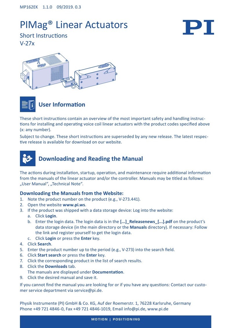
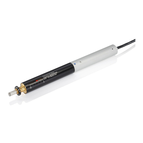
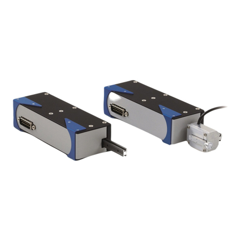
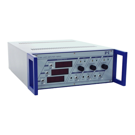
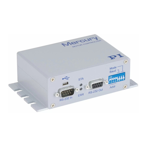
Digitale Motorcontroller
MS242EK Kurzanleitung
C-663 / C-863 / C-867 / C-877 / C-884 / E-861 / E-871 / E-873
Benutzerinformaon
Diese Kurzanleitung enthält eine Übersicht der wichgsten Sicherheitshinweise und Handlungs-
anweisungen zur Installaon und Inbetriebnahme für Motorcontroller mit den oben angegebenen
Produktnummern.
Handbuch herunterladen und lesen
Für die Handlungsschrie bei Installaon, Inbetriebnahme, Betrieb, Anpassen von Einstellungen
und Wartung sind zusätzliche Informaonen aus den Handbüchern des Controllers und/oder des
verwendeten Verstellers erforderlich.
Mögliche Bezeichnungen für Handbücher: „Benutzerhandbuch“, „User Manual“, „Technical Note“.
Handbücher von der Website herunterladen
1. Lesen Sie die Produktnummer (z. B. C-863.11) am Produkt ab.
2. Önen Sie die Website www.pi.de.
3. Für kennwortgeschützte Handbücher (CD im Lieferumfang des Produkts):
a. Legen Sie die CD in einen PC ein.
b. Lesen Sie Benutzername und Kennwort in der Datei Releasenews im CD-Verzeichnis
\Manuals ab.
c. Klicken Sie auf Login.
d. Melden Sie sich mit dem Benutzernamen und dem Kennwort an.
4. Klicken Sie auf Suche.
5. Geben Sie die Produktnummer bis zum Punkt (z. B. C-863) in das Suchfeld ein.
6. Klicken Sie auf Suche starten oder drücken Sie die Enter-Tas te.
7. Wenn nög: Klicken Sie am Ende der Liste auf Weitere Suchergebnisse laden.
8. Klicken Sie auf das entsprechende Produkt, um die Produktdetailseite zu önen.
9. Scrollen Sie nach unten zum Bereich Downloads.
Die Handbücher werden unter Dokumentaon angezeigt.
10. Klicken Sie auf das gewünschte Handbuch und speichern Sie es auf der Festplae Ihres PC oder
auf einem Datenträger.
Wenn das gesuchte Handbuch nicht gefunden werden kann oder Fragen aureten: Kontakeren
MS242EK 1.2.0 12/2017. 0.5
Seite 1 of 8
Seite 5 von 8 Seite 6 von 8 Seite 7 von 8 Seite 8 von 8
Seite 4 von 8Seite 3 von 8Seite 2 von 8
Gesellschaen
Physik Instrumente (PI) GmbH & Co. KG
Auf der Römerstraße 1
76228 Karlsruhe
Deutschland
Tel. +49 721 4846-0
Fax +49 721 4846-1019
www.pi.de
PI miCos GmbH
Freiburger Straße 30
79427 Eschbach
Deutschland
Tel. +49 7634 5057-0
Fax +49 7634 5057-99
www.pi.de
PI Ceramic GmbH
Lindenstraße
07589 Lederhose
Deutschland
Tel. +49 36604 882-0
Fax +49 36604 882-4109
www.piceramic.de
Niederlassungen
US PI (Physik Instrumente) L.P.
www.pi-usa.us
GB PI (Physik Instrumente) Ltd.
www.physikinstrumente.co.uk
IT Physik Instrumente (PI) S. r. l.
www.pionline.it
NL PI Benelux B.V.
www.pi.ws
FR PI France SAS
www.pi.ws
ES Micos Iberia S.L.
www.pimicos.es
JP PI Japan Co., Ltd.
www.pi-japan.jp
CN Physik Instrumente (PI Shanghai) Co., Ltd.
www.pi-china.cn
SG PI (Physik Instrumente) Singapore LLP
www.pi-singapore.sg
TW Physik Instrumente (PI) Taiwan Ltd.
www.pi-taiwan.com.tw
KR PI Korea Ltd.
www.pikorea.co.kr
4. Wenn nög: Führen Sie im Schri Start up
axes die Referenzfahrt für die Achse aus,
damit der Controller die absolute Achsposi-
on kennt.
a. Klicken Sie auf die entsprechende
Schalläche, um die Referenzfahrt zu
star ten:
▪▪Ref. switch: Referenzfahrt zum Refe-
renzschalter
▪▪Neg. limit: Referenzfahrt zur ne-
gaven physikalischen Grenze des
Stellwegs
▪▪Pos. limit: Referenzfahrt zur posiven
physikalischen Grenze des Stellwegs
b. Wenn eine Warnmeldung erscheint,
dass der Servomodus ausgeschaltet ist:
Schalten Sie den Servomodus durch
einen Klick auf die Schalläche Switch
on servo ein (geregelter Betrieb).
c. Nach erfolgreicher Referenzfahrt kli-
cken Sie auf OK > Close.
Das Haupenster von PIMikroMove® önet
sich.
XStarten Sie einige Testbewegungen der
Achse.
a. Setzen Sie die Schriweite auf eine für
Ihre Testbewegungen sinnvollen Wert
(Spalte Step size, 1).
b. Um Bewegungen in die entsprechende
Richtung mit der ausgewählten Schri-
weite auszuführen, klicken Sie auf die
Pfeiltasten (< und >, 2).
Abhängig von Antriebstyp und Last können
für eine schnelle und präzise Posionierung
Parameteranpassungen notwendig sein (siehe
Handbuch).
PIMikroMove®: Haupenster
1 Feld Step size
2 Pfeiltasten
PIMikroMove®: Connect controller
1 Feld für die Controllerauswahl
2 Registerkarten für Schnistelle und Verbin-
dungsart
3 Schnistellenparameter
4 Schalläche Connect
2. Wählen Sie im Feld für die Controlleraus-
wahl (1) den entsprechenden Controller
aus.
3. Wählen Sie auf der rechten Seite des Fen-
sters die Registerkarte aus, die der Schni-
stelle und Verbindungsart des Controllers
entspricht (2).
4. Wenn nög: Stellen Sie die Schnistellen-
parameter passend zum Controller ein (3).
5. Wenn nög: Wählen Sie den Controller aus
der Liste aus (3).
6. Klicken Sie auf die Schalläche Connect (4),
um die Kommunikaon herzustellen.
Bewegungen starten
HINWEIS
Die Auswahl eines falschen Verstellertyps
in der PC-Soware kann Schäden am
Versteller verursachen.
XStellen Sie sicher, dass der in der
PC-Soware ausgewählte Verstel-
lertyp mit dem angeschlossenen
Versteller übereinsmmt.
Wenn sich das Fenster Stage Type Congura-
on önet:
XKlicken Sie auf die Schalläche Yes, con-
gure for ..., um den passenden Parameter-
satz aus einer Verstellerdatenbank zu laden.
Wenn im Fenster Start up controller der Schri
Select connected stages angezeigt wird:
PIMikroMove®: Select connected stages
1 Feld Stage database entries
2 Schalläche Assign
3 Schalläche Assign Type from ID Chip
4 Schalläche OK
1. Wählen Sie den passenden Verstellertyp
aus.
a. Markieren Sie den passenden Verstel-
lertyp im Feld Stage database entries
(1).
b. Klicken Sie auf Assign (2).
oder
XKlicken Sie auf Assign Type from ID
Chip (3)
2. Bestägen Sie die Auswahl mit OK (4), um
die Parametereinstellungen für den ausge-
wählten Verstellertyp aus der Verstellerda-
tenbank zu laden.
3. Wählen Sie im Fenster Save all changes
permanently?, ob die Einstellungen des
Controllers temporär oder permanent
gespeichert werden sollen:
▪▪Keep the changes temporarily: Die
Einstellungen werden nach einem
Neustart des Controllers wieder zurück-
gesetzt.
▪▪Save all sengs permanently on
controller: Alle Einstellungen werden
in den permanenten Speicher des
Controllers übernommen und stehen
auch nach einem Neustart oder für die
Verwendung mit anderer Soware zur
Verfügung.
Inbetriebnahme
Für die erste Inbetriebnahme wird die PC-So-
ware PIMikroMove® empfohlen. Mit PIMi-
kroMove® können Sie die Einstellungen des
Controllers temporär oder dauerha an den
verwendeten Versteller anpassen und erste
Bewegungen starten.
VORSICHT
Bei fehlendem oder nicht ordnungs-
gemäß angeschlossenem Schutzleiter
kann das Berühren des Controllers im
Fehlerfall zu leichten Verletzungen durch
Stromschlag führen.
XSchließen Sie den Controller vor
Inbetriebnahme an einen Schutzlei-
ter an.
XEnernen Sie den Schutzleiter nicht
während des Betriebs.
XBeachten Sie die geltenden Normen
für die Schutzleiterbefesgung.
Voraussetzungen
✔Sie haben das PIMikroMove® Handbuch
und die allgemeinen Hinweise zur Inbe-
triebnahme gelesen und verstanden. Die
Soware-Handbücher nden Sie auf der CD
des Controllers.
✔Sie haben die Soware auf dem PC instal-
liert und aktualisiert.
✔Sie haben Versteller und Controller so
installiert, wie sie in Ihrer Anwendung
eingesetzt werden.
✔Sie haben Schutzleiter, Versteller, PC und
Netzteil am Controller angeschlossen.
✔Wenn Sie den Controller über die TCP/
IP-Schnistelle am Netzwerk oder PC ange-
schlossen haben:
▪▪Netzwerk mit DHCP-Server: Keine
Anpassung der werkseigen Einstel-
lungen der Schnistellenparameter
notwendig.
▪▪Netzwerk ohne DHCP-Server oder mit
Direktverbindung (Controller direkt an
der Ethernet-Anschlussbuchse des PC
angeschlossen):
▪▪Das Startup-Verhalten des Controllers
muss so geändert werden, dass der
Controller eine stasche IP-Adresse
verwendet (siehe Handbuch).
▪▪IP-Adressen und Subnetzmasken von
Controller und PC bzw. allen weiteren
Netzwerkteilnehmern müssen auf-
einander abgesmmt werden (siehe
Handbuch).
✔Wenn vorhanden: Sie haben die DIP-Schal-
ter des Controllers passend zu Ihrer Anwen-
dung eingestellt. Ein Controller, der nicht
Bestandteil eines Daisy-Chain-Netzwerks
ist, muss die Adresse 1 haben, wenn er in
PIMikroMove® verwendet werden soll.
DIP-Schalter
Adresse 12345... 16
DIP 1 ON ON ON ON ON ... OFF
DIP 2 ON ON ON ON OFF ... OFF
DIP 3 ON ON OFF OFF ON ... OFF
DIP 4 ON OFF ON OFF ON ... OFF
Baudrate 9600 19200 38400 115200
DIP 5 ON ON OFF OFF
DIP 6 ON OFF ON OFF
Controller einschalten
1. Verbinden Sie das Netzkabel des Netzteils
mit der Steckdose.
2. Wenn nög: Bringen Sie den Kippschalter
des Controllers in die Stellung ❙.
Kommunikaon mit PIMikroMove®
herstellen
1. Starten Sie PIMikroMove®.
Das Fenster Start up controller önet sich
mit dem Schri Connect controller.
XWenn sich das Fenster Start up control-
ler nicht automasch önet, wählen
Sie im Haupenster den Menüeintrag
Connecons > New….
PC anschließen
HINWEIS
Das gleichzeige Anschließen der
USB- und der RS-232-Schnistelle des
Controllers an den PC kann den PC oder
den Controller beschädigen.
XSchließen Sie entweder die USB-
oder die RS-232-Schnistelle an den
PC an.
Voraussetzungen
✔Der PC verfügt über eine freie RS-232- oder
USB-Schnistelle.
oder
✔Für den Controller ist ein freier Zugangs-
punkt zum Netzwerk vorhanden.
Werkzeug und Zubehör
▪▪Geeignetes Kabel, z. B.
▪▪RS-232-Nullmodemkabel
▪▪USB-Kabel
▪▪Straight-Through- oder Crossover- Netz-
werkkabel
An USB-Schnistelle anschließen
XVerbinden Sie die USB-Buchse des Control-
lers über das USB-Kabel mit einer freien
USB-Schnistelle des PC.
An RS-232-Schnistelle anschließen
1. Verbinden Sie den RS-232-Stecker des Con-
trollers über das RS-232-Nullmodemkabel
mit einer freien RS-232-Schnistelle des PC.
2. Sichern Sie die Steckverbindung mit den
integrierten Schrauben gegen unbeabsich-
gtes Abziehen.
An ein Netzwerk anschließen
XVerbinden Sie die RJ-45-Buchse des Con-
trollers über das Netzwerkkabel mit dem
Netzwerk-Zugangspunkt oder PC.
Netzteil an Controller anschließen
Voraussetzungen
✔Das Netzkabel ist nicht an der Steckdose
angeschlossen.
Werkzeug und Zubehör
▪▪Mitgeliefertes Netzteil oder korrekt bemes-
senes Netzteil
▪▪Wenn nög: Mitgelieferter Adapter für den
Netzteilanschluss oder korrekt bemessener
Adapter
▪▪Mitgeliefertes Netzkabel oder korrekt
bemessenes Netzkabel
Netzteil mit Adapter an den Controller an-
schließen
1. Verbinden Sie den Adapter (3) mit dem
Netzteilanschluss (Einbaustecker, 4) des
Controllers.
2. Verbinden Sie den Hohlstecker des Ad-
apters (2) mit der Hohlstecker-Kupplung
des Netzteils (1).
3. Verbinden Sie das Netzkabel mit dem
Netzteil.
Controller mit Einbaustecker M8
Controller mit Einbaustecker D-Sub 2W2C
1 Hohlstecker-Kupplung des Netzteils
2 Hohlstecker des Adapters
3 Kupplung des Adapters
4 Netzteilanschluss des Controllers
Netzteil ohne Adapter an den Controller
anschließen
XVerbinden Sie die das Netzteil mit dem
Netzteilanschluss des Controllers.
XVerbinden Sie das Netzkabel mit dem
Netzteil.
Controller moneren
HINWEIS
Hohe Temperaturen können den Control-
ler überhitzen.
XInstallieren Sie den Controller mit
einem Abstand von mindestens
10 cm zur Ober- und Rückseite und
mindestens 5 cm zu dessen Seiten.
Wenn dies nicht möglich ist, kühlen
Sie die Umgebung ausreichend.
XSorgen Sie für ausreichende Belüf-
tung am Aufstellungsort.
XHalten Sie die Umgebungstempe-
ratur auf einem unkrischen Wert
(5-40 °C).
Wenn der Controller als Tischgerät verwendet
werden soll:
XSorgen Sie für einen sicheren und stabilen
Stand des Controllers.
Wenn der Controller monert werden soll:
1. Bringen Sie die erforderlichen Bohrungen in
die Unterlage ein.
2. Befesgen Sie den Controller mit jeweils
einer ausreichend bemessenen Schraube
pro Aussparung.
Controller an Schutzleiter anschließen
Wenn ein Schutzleiteranschluss am Controller
vorhanden ist, muss dieser mit einem Schutzlei-
ter verbunden werden.
Voraussetzungen
✔Der Controller ist ausgeschaltet.
Werkzeug und Zubehör
▪▪Geeigneter Schutzleiter:
▪▪Kabelquerschni ≥0,75 mm²
▪▪Übergangswiderstand <0,1 Ohm bei
25 A an allen für die Schutzleitermon-
tage relevanten Stellen
▪▪Befesgungsmaterial für den Schutzleiter,
sitzt bei Auslieferung des Controllers auf
dem Schutzleiteranschluss
▪▪Geeigneter Schraubenschlüssel
Schutzleiter anschließen
1. Geeigneten Kabelschuh am Schutzleiter
befesgen.
2. Kabelschuh des Schutzleiters mit mitgelie-
fertem Befesgungsmaterial am Schutzlei-
teranschluss befesgen.
Schutzleiter über Gewindebolzen anschließen
1 Gewindebolzen
2 Unterlegscheibe
3 Kabelschuh mit Schutzleiter
4 Sicherungsscheibe
5 Muer
Versteller anschließen
HINWEIS
Das Anschließen eines Verstellers
mit inkompabler Antriebsart an den
Controller kann irreparable Schäden am
Versteller oder Controller verursachen.
Auch Versteller mit mechanisch kompa-
blen Steckverbindern können elektrisch
inkompabel zum Controller sein.
XSchließen Sie an den Controller nur
Versteller mit kompabler Antriebs-
art an.
Voraussetzungen
✔Der Controller ist ausgeschaltet.
✔Sie haben das Benutzerhandbuch des Ver-
stellers gelesen und verstanden.
Werkzeug und Zubehör
▪▪Versteller mit kompablem Antriebstyp
und Stecker
▪▪Wenn nög: Kompabler Adapter von PI
▪▪Oponal: geeignetes Verlängerungskabel
von PI
Versteller anschließen
1. Schließen Sie den Motorstecker des Ver-
stellers an der Buchse Motor des Control-
lers an.
2. Wenn nög: Schließen Sie den Sensor-
stecker des Verstellers am Einbaustecker
Sensor des Controllers an.
3. Sichern Sie die Steckverbindungen mit den
integrierten Schrauben gegen unbeabsich-
gtes Abziehen.
Allgemeine
Sicherheitshinweise
Besmmungsgemäße Verwendung
Der Controller ist ein Laborgerät im Sinne der
DIN EN 61010-1. Er ist für die Verwendung in
Innenräumen und in einer Umgebung vorgese-
hen, die frei von Schmutz, Öl und Schmiermit-
teln ist.
Entsprechend seiner Bauform ist der Control-
ler für den geregelten Betrieb von Verstellern
vorgesehen. Außerdem kann er die Referenz-
und Endschaltersignale des angeschlossenen
Verstellers auslesen und weiterverarbeiten.
Der Controller darf nur unter Einhaltung der
technischen Spezikaonen und Anweisungen
im Benutzerhandbuch verwendet werden. Für
die Prozessvalidierung ist der Benutzer verant-
wortlich.
Der Controller darf nicht für andere als die
im Benutzerhandbuch genannten Zwecke
verwendet werden. Nur autorisiertes und
entsprechend qualiziertes Personal darf den
Controller installieren, bedienen, warten und
reinigen.
Installaon
Ungeeignete Kabel können Schäden am
Controller verursachen und die Leistung des
Verstellers beeinussen.
XVerwenden Sie für den Anschluss des Ver-
stellers an den Controller nur Originalteile
von PI.
XWenn Sie längere Kabel benögen, verwen-
den Sie Verlängerungskabel von PI.
Inbetriebnahme
Der Aufprall eines bewegten Teils am Ende des
Stellwegs oder auf einem Hindernis sowie hohe
Beschleunigungen können Schäden oder erheb-
lichen Verschleiß am Versteller verursachen.
XVermeiden Sie Bewegungen im ungere-
gelten Betrieb oder stoppen Sie die Achse
rechtzeig. Deakvieren Sie nicht per
Parametereinstellung die Endschalteraus-
wertung durch den Controller.
Ungeeignete Einstellungen der Regelparame-
ter des Controllers können den Versteller zum
Schwingen bringen. Schwingungen können den
Versteller und/oder die auf ihm angebrachte
Last beschädigen.
XWenn der Versteller schwingt (ungewöhn-
liches Laufgeräusch), schalten Sie den
Servomodus oder den Controller sofort aus.
XSchalten Sie den Servomodus erst wieder
ein, nachdem Sie die Einstellungen der
Regelparameter des Controller geändert
haben (siehe Handbuch).
XWenn aufgrund einer sehr hohen Last
Schwingungen bereits während der
Referenzfahrt aureten, folgen Sie für die
Referenzfahrt den Anweisungen in „Stö-
rungsbehebung“ im Handbuch.
Installaon
PC-Soware installieren
Soware auf Windows installieren
1. Starten Sie den Installaonsassistenten,
indem Sie im Installaonsverzeichnis
(Hauptverzeichnis der CD) auf die Datei
PI_<Produktnummer>.CD_Setup.exe
doppelklicken.
Das Fenster InstallShield Wizard für die
Installaon von Programmen und Handbü-
chern für den Controller önet sich.
2. Folgen Sie den Anweisungen am Bildschirm.
3. Wenn nög: Aktualisieren Sie PC-Soware
und Verstellerdatenbank mit dem PIUp-
dateFinder (siehe Handbuch).
Soware auf Linux installieren
1. Entpacken Sie das tar-Archiv aus dem
Verzeichnis /linux der Produkt-CD in ein
Verzeichnis auf Ihrem PC.
2. Wechseln Sie in das Verzeichnis, in das Sie
das tar-Archiv entpackt haben.
3. Führen Sie als Superuser (Root-Rechte) das
Script ./INSTALL aus, um die Installaon zu
starten.
4. Folgen Sie den Anweisungen am Bildschirm.
5. Wenn nög: Aktualisieren Sie die PC-So-
ware und Verstellerdatenbank (siehe
Handbuch).
BEWEGEN | POSITIONIEREN BEWEGEN | POSITIONIERENBEWEGEN | POSITIONIERENBEWEGEN | POSITIONIEREN


