Page 1.2 2-SLOT LXI/USB MODULAR CHASSIS 60-104
pickering
SECTION 1 - TECHNICAL SPECIFICATION
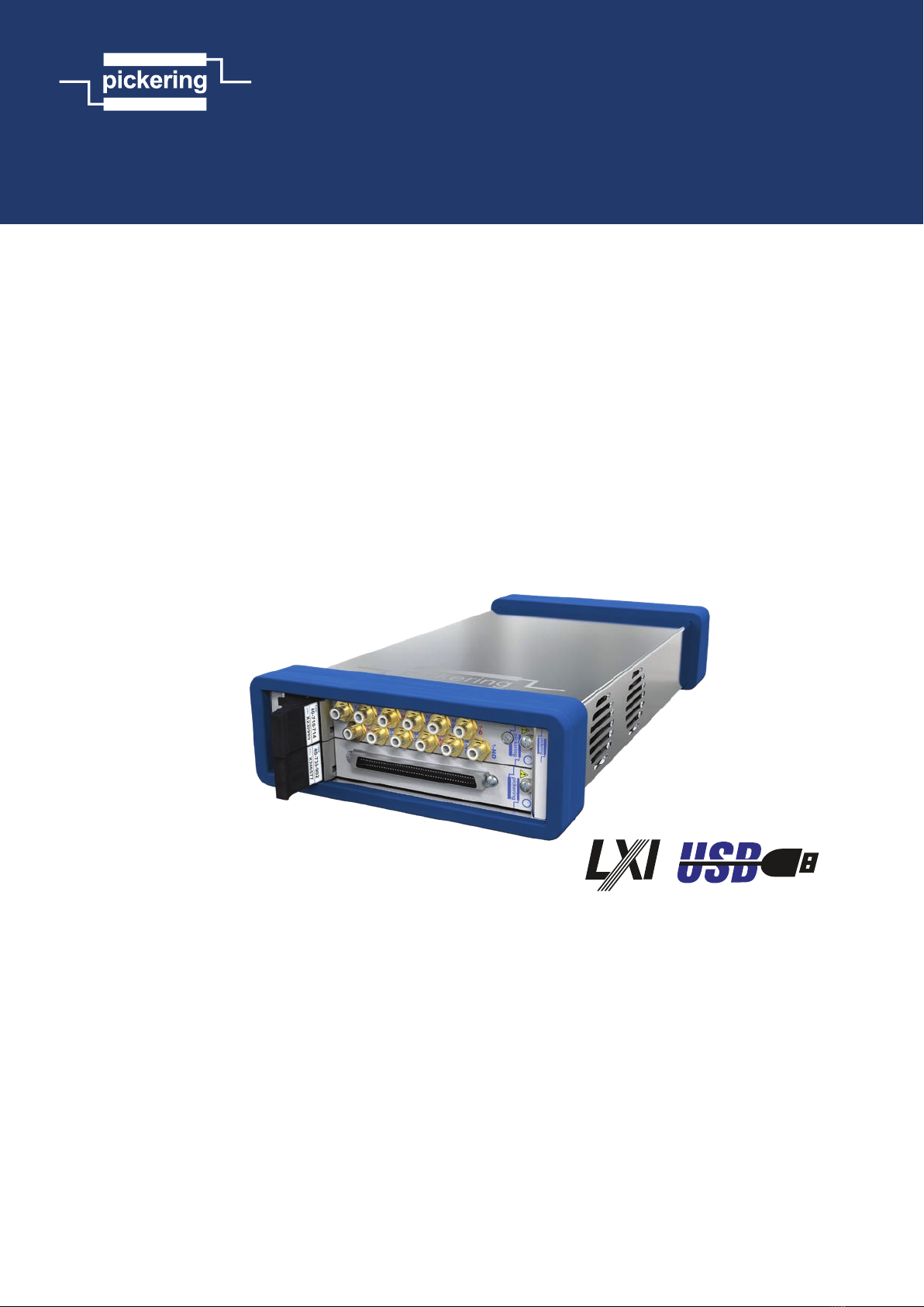
LXI/USB 2-Slot Modular Chassis, 60-104
pickeringtest.com
Specifications & Ordering Information
Operating/Storage Conditions
Operating Conditions
Operating Temperature:
Humidity:
Altitude:
0°C to +55°C
Up to 90% non-condensing
5000m
Storage and Transport Conditions
Storage Temperature:
Humidity:
Altitude:
-20°C to +75°C
Up to 90% non-condensing
15000m
Safety, CE & RoHS Compliance
All products are fully CE compliant and meet
applicable EU directives: Low-voltage safety EN61010-
1:2010, EMC Immunity EN61326-1:2013, Emissions
EN55011:2009+A1:2010.
The 60-105 Chassis also complies with the European
Restriction of Hazardous Substances directive (RoHS).
Product Order Codes
Chassis
LXI/USB Modular Switching Chassis, 2-Slot 60-104-001
Accessories
Replacement 19V DC Power Supply 63-104-001
400Hz 19V DC power supply 63-104-001-400
Optional Wi-Fi Dongle 63-104-002
Optional Chassis Strap Mounting Kit* 63-104A-003
Optional Chassis Plate Mounting Kit* 63-104A-004
Optional Chassis Low Profile Mounting Kit* 63-104-005
Optional Chassis Rack Mounting Kit 63-104-006
* Please refer to the 60-104 User Manual for information on these
optional chassis mounting kits.
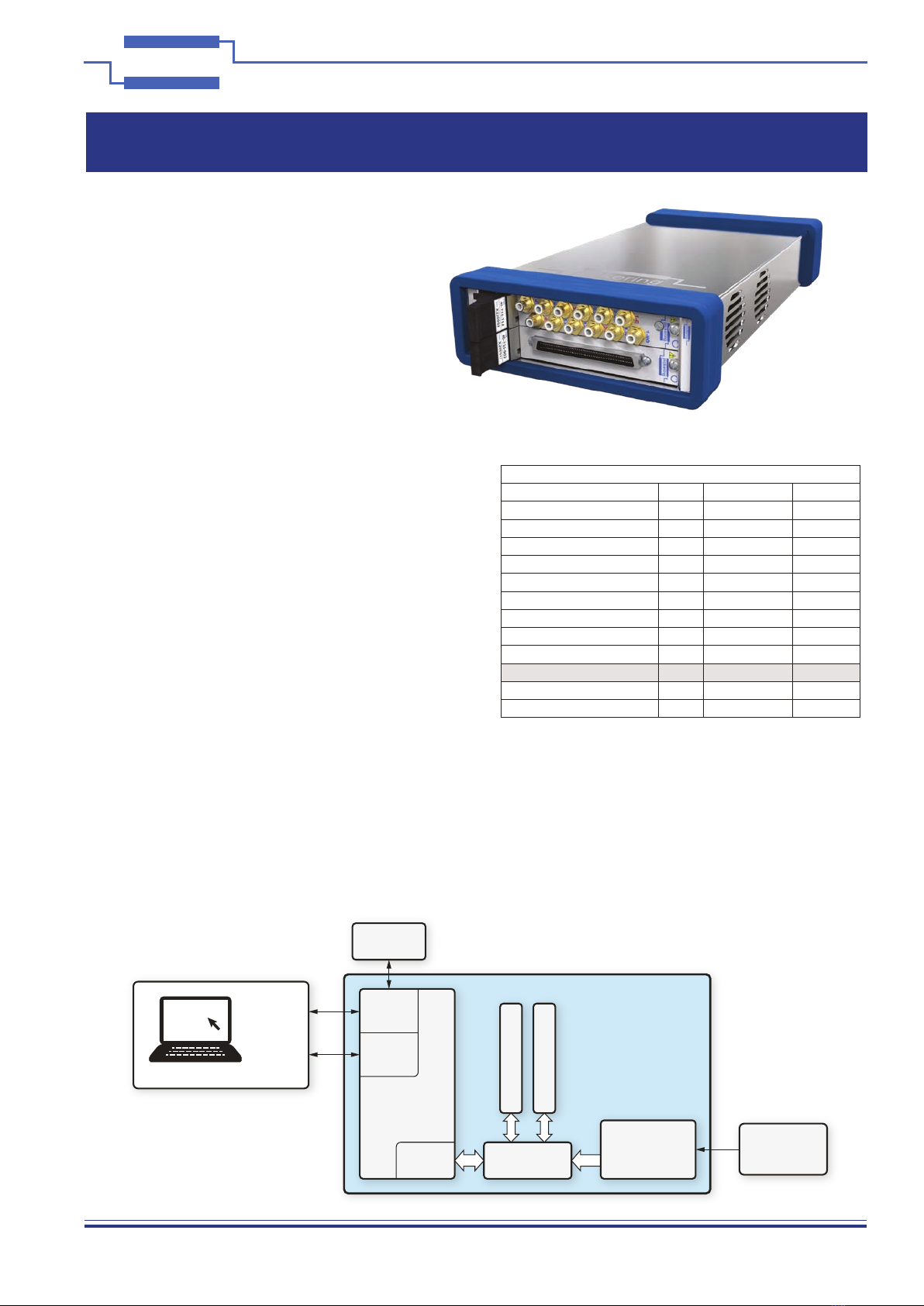
Chassis Backplane: 32-bit cPCI backplane, compatible
with PXI.
Chassis Capacity: 2 off 3U user slots available.
PXI Module compatibility
The chassis is supplied with drivers for Pickering PXI modules.
Switching Support: Most of 3U Pickering Interface’s
PXI switching modules. Includes
(but not limited to): All 2 slot 3U
BRIC matrices, featuring up to 1104
crosspoints.
Simulation support: All programmable resistor and
potentiometer modules offering
up to 36 channels, RF attenuators,
digital I/O and other simulation
modules.
Power Supply
Input Voltage Range:
Input Current Rating:
19V (DC)
5.2A (DC)
Cooling
Airflow:
Per-slot Cooling Capacity:
Fans:
Crossflow
25W at 40°C ambient
2 off 7.7 cfm fans
Acoustic Noise Emissions
With fans on maximum: 53dBA typical
LAN Interface
Designed to comply with the LXI Standard Version 1.5
Connector: RJ45 Connector.
Connection Speed: 1000BaseT interface.
USB Interface
Compatible with USB3 (backwardly compatible with USB/USB2)
Connector: USB3 type B
Connection Speed: 400MBps
Mechanical Specification
Dimensions:
With Rubber Bumpers:
Width: 165mm (6.50”)
Height: 58mm (2.28”)
Depth: 308mm (12.13”)
Weight: 1.3kg without PXI modules
External PSU Dimensions:
Lead Length:
W: 58mm, H: 37mm, D: 142mm
1200mm
+3.3V +5V +12V -12V
6A 6A 1A 1A
NOTE: Maximum power is 60W for all slots or 30W per slot.
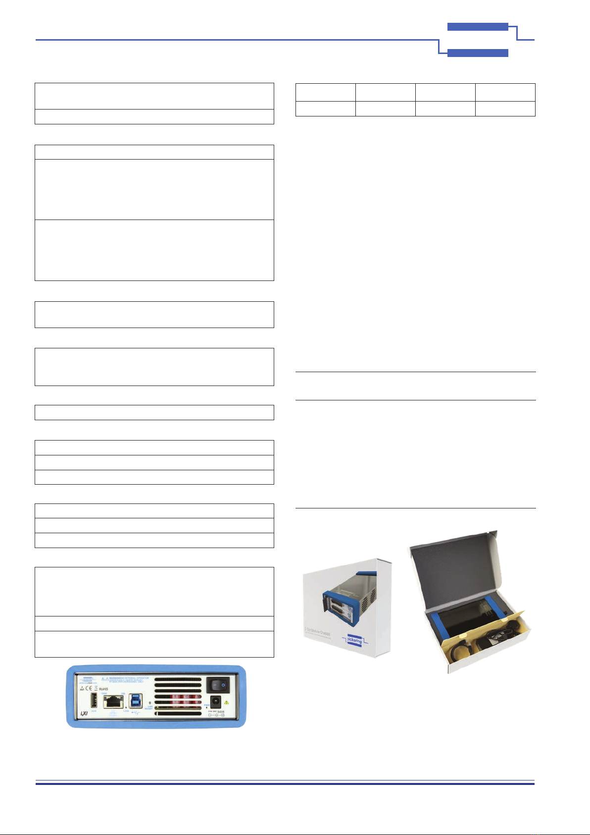
The 60-104 LXI/USB Modular Chassis Front Panel
The 60-104 2-Slot LXI/USB Modular Chassis is Shipped
With Everything You Need to Get Started.
The Package Includes: ●60-104 Chassis ●Power Supply
●USB3 Cable ●Ethernet Cable ●Driver DVD