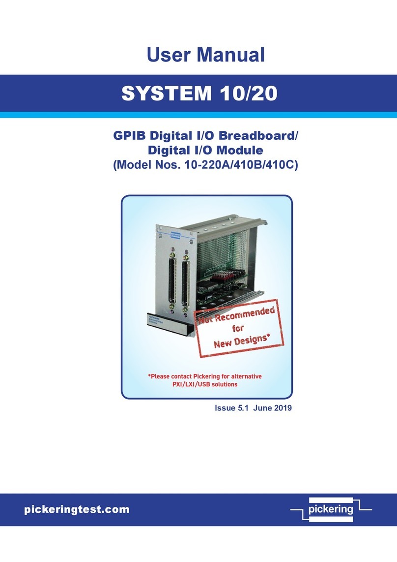
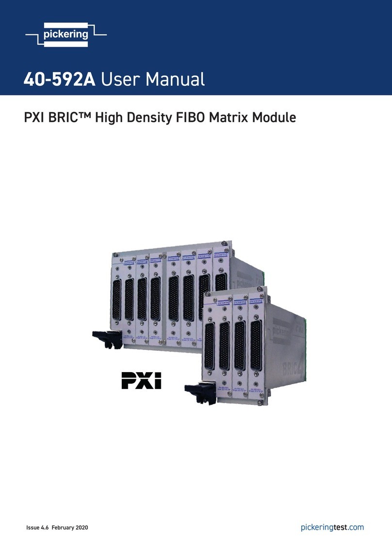
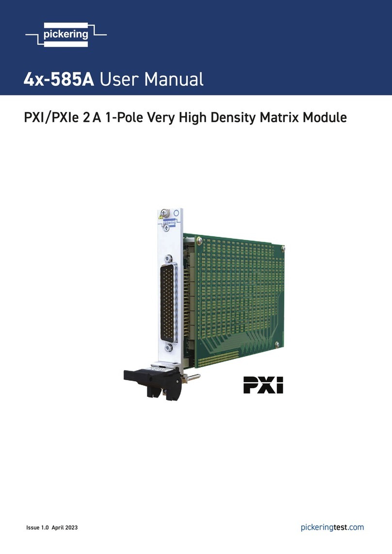
Pickering 4 890 Series User manual
Other Pickering Control Unit manuals
Pickering
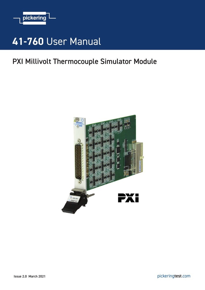
Pickering 41-760 User manual
Pickering
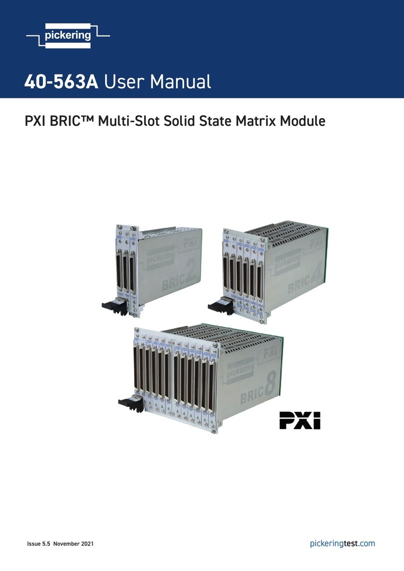
Pickering PXI BRIC 40-563A User manual

Pickering
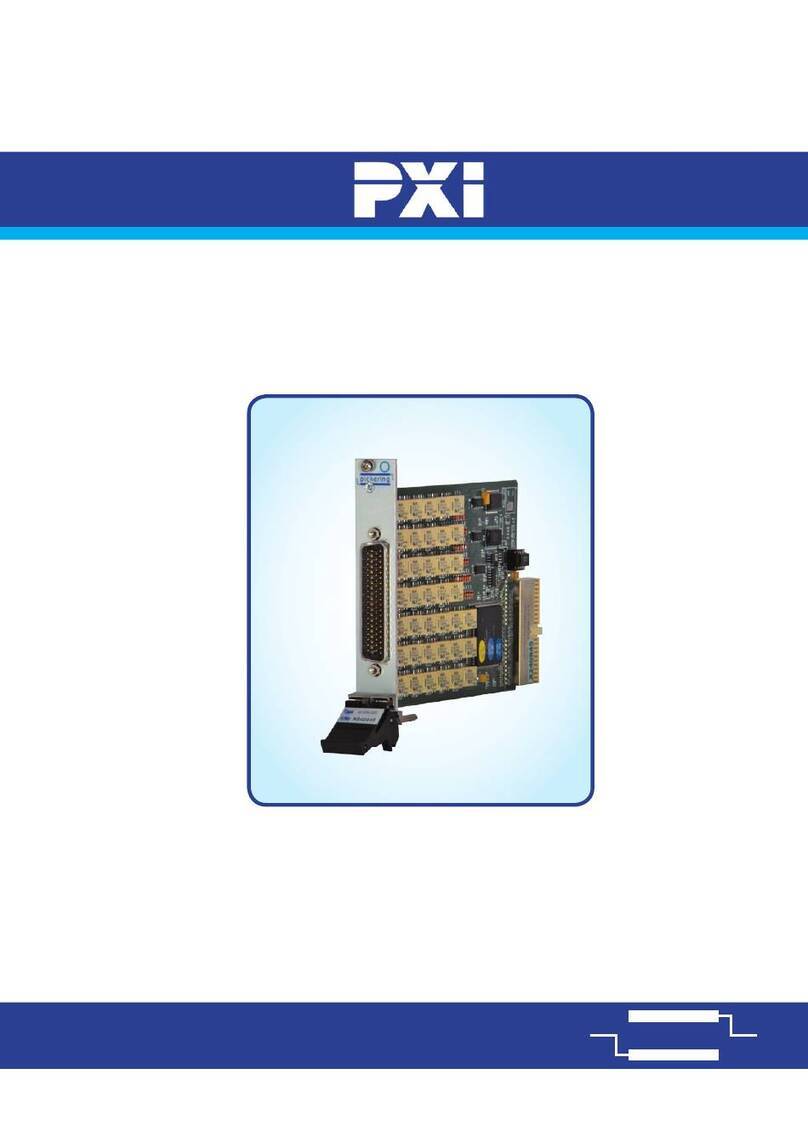
Pickering 45-542 User manual
Pickering
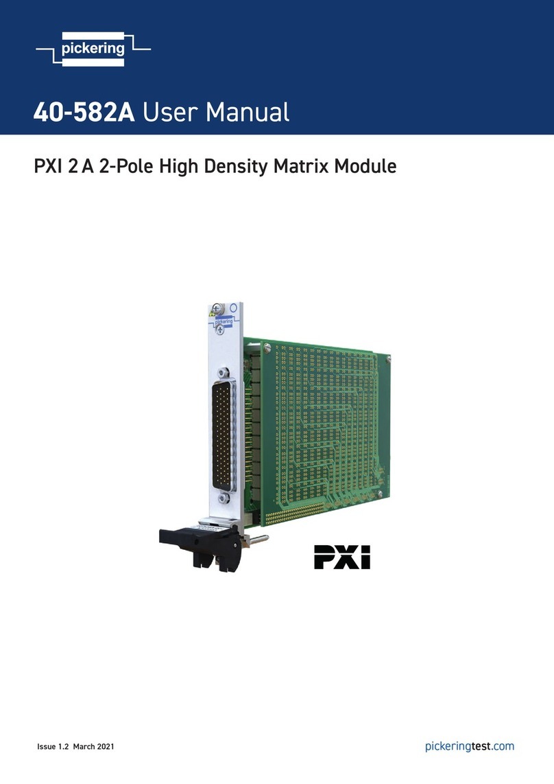
Pickering 40-656A User manual
Pickering
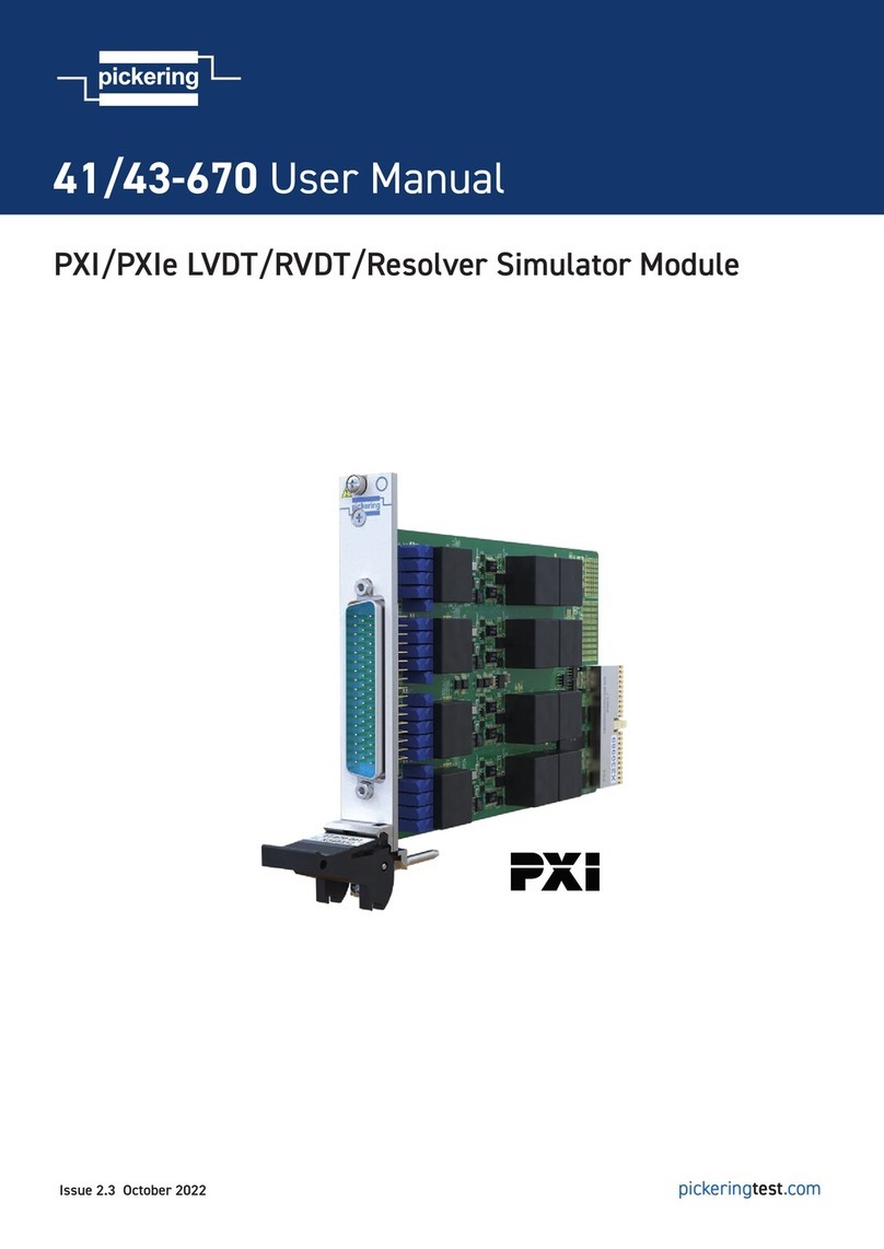
Pickering 40-582A User manual
Pickering
Pickering 41-670 User manual

Pickering
Pickering Pxi 41-750 User manual

Pickering
Pickering PXI 40-795-001 User manual

Pickering
Pickering 41-761 User manual
Pickering
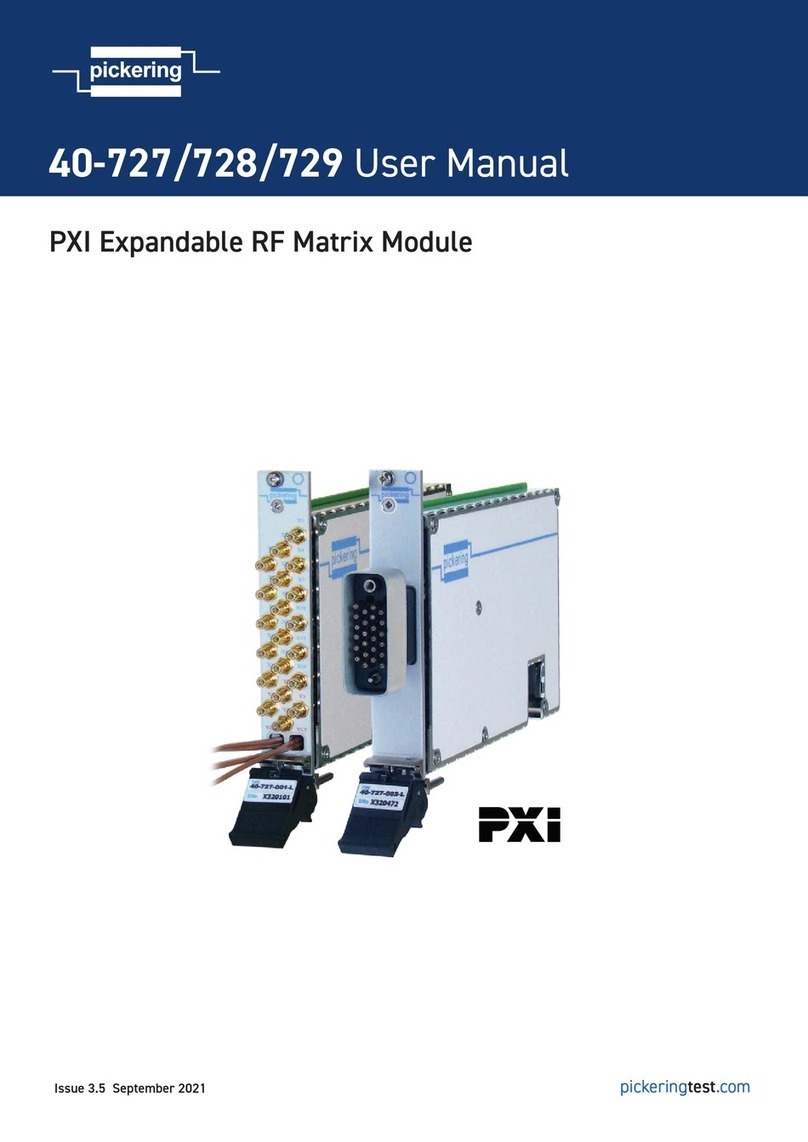
Pickering 40-727 User manual

Pickering
Pickering PXi 41-720 User manual
Pickering
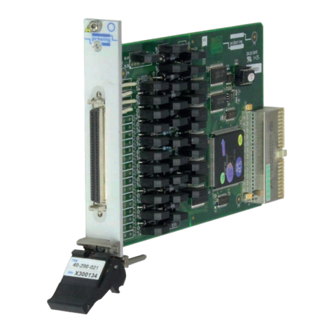
Pickering 40-290-021 User manual
Pickering
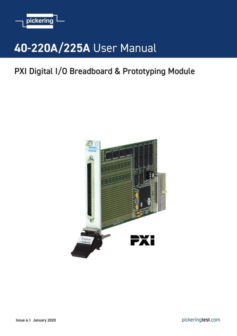
Pickering 40-220A User manual
Pickering
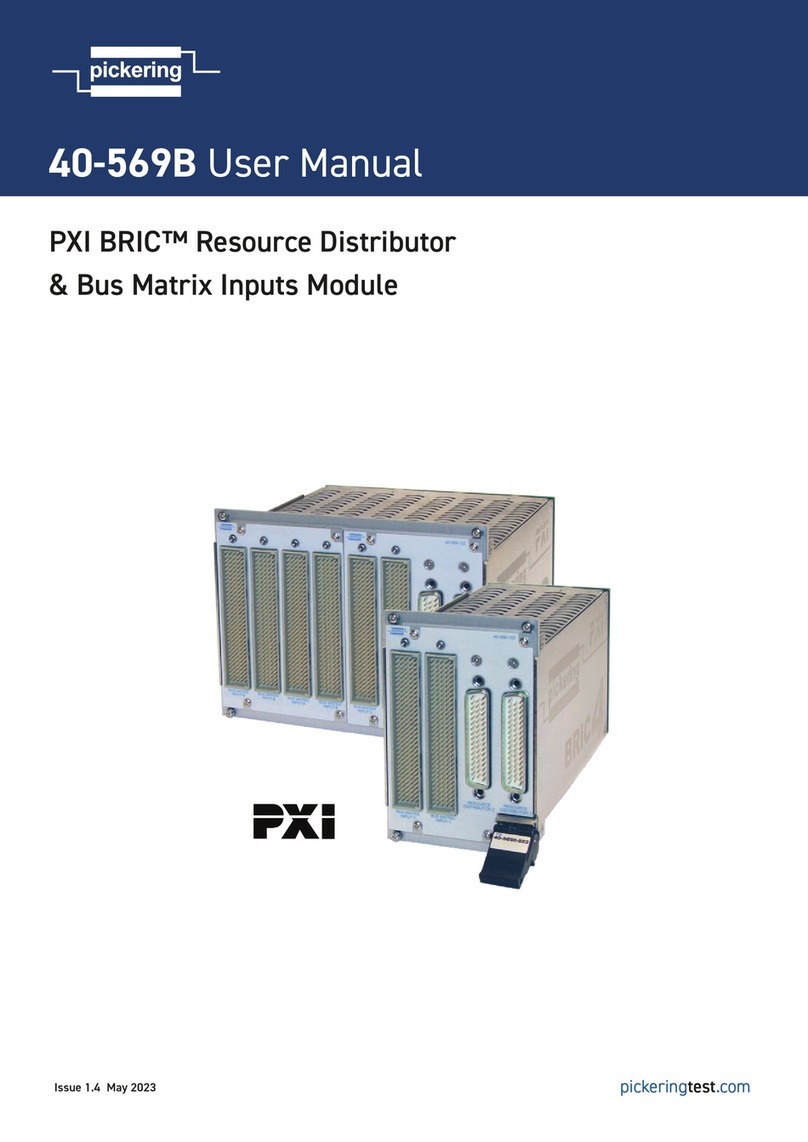
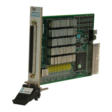
Pickering PXI BRIC 40-569B User manual
Pickering
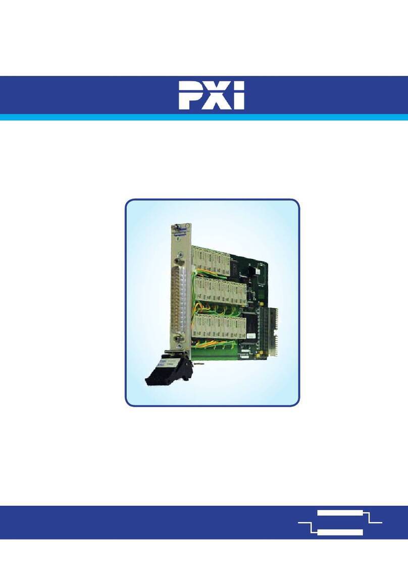
Pickering 40-670 User manual
Pickering
Pickering 40-650A User manual
Pickering
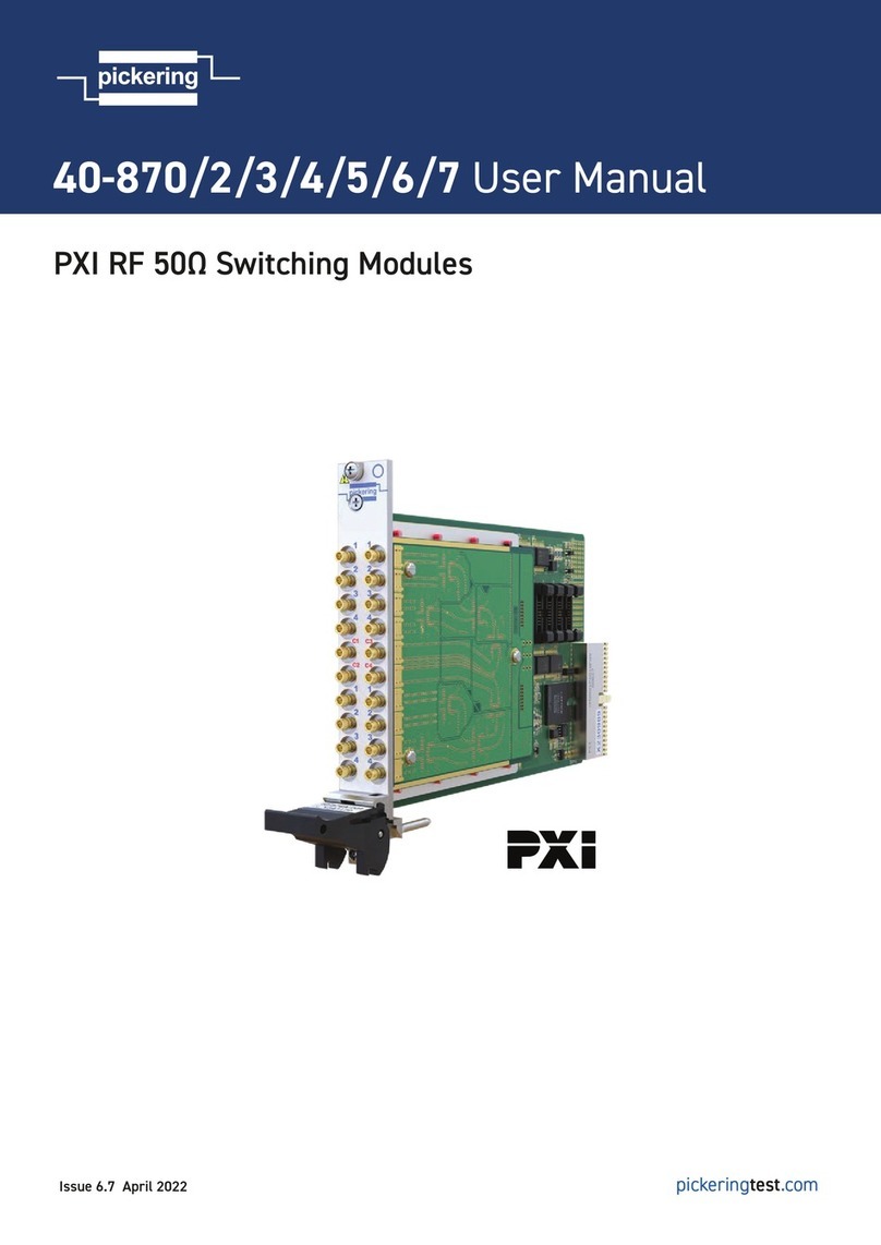
Pickering 40-870 User manual

Pickering
Pickering 41-735 User manual
Pickering
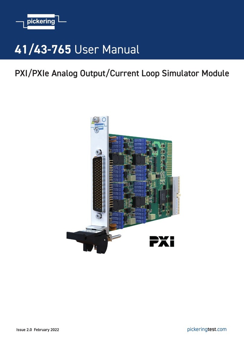
Pickering 41-765 User manual
Pickering
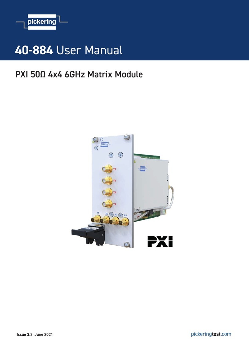
Pickering 40-884 User manual
Popular Control Unit manuals by other brands

Festo
Festo Compact Performance CP-FB6-E Brief description

Elo TouchSystems
Elo TouchSystems DMS-SA19P-EXTME Quick installation guide

JS Automation
JS Automation MPC3034A user manual

JAUDT
JAUDT SW GII 6406 Series Translation of the original operating instructions

Spektrum
Spektrum Air Module System manual

BOC Edwards
BOC Edwards Q Series instruction manual

KHADAS
KHADAS BT Magic quick start

Etherma
Etherma eNEXHO-IL Assembly and operating instructions

PMFoundations
PMFoundations Attenuverter Assembly guide

GEA
GEA VARIVENT Operating instruction

Walther Systemtechnik
Walther Systemtechnik VMS-05 Assembly instructions

Altronix
Altronix LINQ8PD Installation and programming manual
