manuals.online logo
Brands
  1. Home
  2. •
  3. Brands
  4. •
  5. Pickering
  6. •
  7. Relay
  8. •
  9. Pickering 200 Series User manual

Pickering 200 Series User manual

Title
pickeringrelay.com
Introduction
Pickering Series 200 Surface Mount Reed Relays have recommended
PCB footprints, a moisture sensitivity level, peak reflow classification,
recommended handling procedures and packing options as outlined in
this document.
Contents
1. PCB Footprints
2. Handling Procedures and Packing Options
3. Soldering
4. Disposal
5. Standards
Series 200 User Guide
Surface Mount Reed Relays
pickeringrelay.com
Page 2
Series 200 User Guide
PCB Footprints
RF Design Considerations
While low frequency use of soldered surface mount relays may pose few problems in terms of board design, higher frequency
use requires careful board design to reduce impedance variability at the leg/pad interface. The recommended footprint for the
200RF relay is detailed below:
2
1
3
4
8
7
6
5
39.37 (1.000)
600.4 (15.25)
100.4 (2.55)
23.6 (0.60)
4.0 (0.102)
Solder mask
expansion area
Dimensions: 0.001” (mm)
200RF Relay
PCB pads
PCB Track
Pin 1
Orientation spot
Figure 1. 200RF Footprint (1 Form A, Package Number 2)
An FR4 pcb substrate with a 14 thou dielectric thickness to ground plane will give 50 Ohm for a 23.6 thou microstrip track.
Lower Frequency Footprints
2
14
3
78.74 (2.000)
600.4 (15.25)
100.4 (2.55)
23.6 (0.60)
4.0 (0.102)
Solder mask
expansion area
Dimensions: 0.001” (mm)
200-1-A Relay
PCB pads
PCB Track
Pin 1
Orientation spot
Figure 2. 200-1-A Footprint (1 Form A, Package Number 1)
2 Form A - Package No 3.
1
5
4
78.74 (2.000)
600.4 (15.25)
100.4 (2.55)
23.6 (0.60)
4.0 (0.102)
Solder mask
expansion area
Dimensions: 0.001” (mm)
200-2-A Relay
PCB pads
PCB Track
2
3
6
Pin 1
Orientation spot
Figure 3. 200-2-A Footprint (2 Form A, Package Number 3)
pickeringrelay.com
Page 3
Series 200 User Guide
1
3
157.48 (4.000)
600.4 (15.25)
100.4 (2.55)
23.6 (0.60)
4.0 (0.102)
Solder mask
expansion area
Dimensions: 0.001” (mm)
200-1-B Relay
PCB pads
PCB Track
2
4
Pin 1
Orientation spot
Figure 4. 200-1-B Footprint (1 Form B, Package Number 4)
1 Form A - Package No 5.
1
3
157.48 (4.000)
787.4 (20.00)
100.4 (2.55)
23.6 (0.60)
4.0 (0.102)
Solder mask
expansion area
Dimensions: 0.001” (mm)
200-1-A Mercury Relay
PCB pads
PCB Track
2
4
UP
Pin 1
Orientation
spot
Figure 5. 200-1-A Mercury Relay Footprint (1 Form A, Package Number 5)
1 Form C - Package No 6.
1
4
787.4 (20.00)
100.4 (2.55)
23.6 (0.60)
4.0 (0.102)
Solder mask
expansion area
Dimensions: 0.001” (mm)
200-1-C Relay
PCB pads
PCB Track
3
6
5
78.74 (2.000)
2
Pin 1
Orientation spot
Figure 6. 200-1-C Footprint (1 Form C, Package Number 6)
pickeringrelay.com
Page 4
Series 200 User Guide
Handling Procedures
Moisture Sensitivity of Surface Mount Reed Relays
Quality and reliability concerns regarding internal damage, cracks and delamination from the solder reflow process have
demanded standardised procedures regarding moisture control for some surface mount devices. Pickering Series 200 Surface
Mount Reed Relays are classified to IPC/JEDEC J-STD-020 MSL1, and thus dry packs and special procedures are not required.
Packing
Pickering 200 Series relays are provided in waffle trays as standard with a minimum order quantity of 730 pieces. The relays can
be provided in tape and reel format, the maximum number of relays per reel being 750.
Figure 7. Relays in a Waffle Tray (200-2-A)
Shelf and Floor Life
Through their moisture sensitivity level 1 classification 200 Series relays have an “infinite floor life” when the conditions are
30 °C/85% RH.
pickeringrelay.com
Page 5
Series 200 User Guide
Soldering
Manual and Oven Soldering
To avoid co-planarity and provide acceptable solder joints and performance a suitable soldering profile must be used. The
recommended soldering temperatures and times are detailed below:
Manual Soldering SMD Reflow
Recommended tip/peak temperature 340 °C/3 secs 245 °C/30 secs
Maximum tip/peak temperature 400 °C/5 secs 270 °C/30 secs
Typical profile - See Graph 1
Notes:
a. Temperatures based on using a lead-free (SAC) alloy.
b. Maximum conditions based on limited trials.
c. Solder wetting is affected by many factors such as storage conditions, handling; choice of alloy,
equipment, ventilation, the board thermal mass and AQL (ref IPC-A-610 class 1,2 or 3).
d. We recommend the customer performs appropriate tests to verify their suitability.
Table 1. SMD Reflow Temperatures/Times
Hand Solder Special Instructions:
The tip should be set to the minimum temperature required to produce a consistent solder joint.
It should first be accurately measured using calibrated equipment (traceable to National and International standards) to
determine whether there is an offset. We recommend any offset is adjusted out by recalibrating the solder iron because the offset
may not be linear across the temperature range.
It may be possible to solder at a lower temperature than indicated and this should always be the aim of an assembler soldering
any type of component. Lower temperatures reduce heat stresses and the possibility of flux within the solder wire being burnt off
too quickly which can create dry joints. Lower temperatures will also help to maximize the tip life.
The solder alloy and tip size will also have an influence. We always recommend using as large a tip size as possible because this
improves the contact. It will also have a better heat mass which means its temperature is less likely to reduce as contact is made
with the component lead and printed circuit board (pcb).
The pcb will also act as a thermal mass. Single layer boards can generally be soldered at a lower temperature than multi-layer
boards or those with extensive grounding.
We recognise there may be other components on pcb that require a higher temperature and/or different tip etc. It may seem
possible to find a set up that works for all components, but this can lead to stresses on the most sensitive components. A
common mistake is to set an iron at its maximum temperature.
In summary, incorrect calibration, tip degradation, insufficient tip contact time/position and thermal mass can mistakenly be
overcome by increasing the temperature. Too hot can be as bad as too cold.!!!
Optimizing the tip size to take into the above variables will usually mean it’s possible to use much lower tip temperature.
pickeringrelay.com
Page 6
Series 200 User Guide
Convection Oven
A typical Convection Oven profile can be found below:
Graph 1. Recommended Lead-free SMD Reflow Profile
Vapor Phase Soldering
A typical Vapor Phase profile can be found below:
Graph 2. Vapor Phase Profile
3URILOH'HWDLOV
&RPPHQWV
3&%'HWDLOV
3URFHVV&KHFNHU
'DWH
2SHUDWRU
3URGXFW
6HULDO
&RPSDQ\1DPH
6LJQDWXUH

VWHYH%DNHU
,%/%/&

3LFNHULQJ,QWHUIDFHV8.
BBBBBBBBBBBBBBBBBBBBBBB
3URILOH&HQWUDO9J
°C
Time
Zone Setpoints (Machine: : IBL BLC420)
240
Z1
60
Zone Setpoints (Machine: : IBL BLC420) Recipe: VP IBL X2 SOAK X2 SIDEProcess Parameters
Solder Type:BLT LFS-UFP-T4
MIN MAX Units
Soak Time (160 - 190°C) : 40 90 Seconds
Time Above (t>217°C) : 30 90 Seconds
Peak Temperature °C : 210 240 °C
205.0
213.2
221.4
229.6
237.8
246.0


 
Peak Temperature °C°C
<---- Channels ----->
25.0 42.5 60.0 77.5 95.0
 


Time Above (> 217 °C)
Seconds ----->
35.0 50.0 65.0 80.0 95.0
 


Soak Time (160-190 °C)
Seconds ----->
55.0 90.7 126.4 162.1 197.8
 


Ramp Time (40 - 160 °C)
Seconds ----->








Heating Rate(°C/Sec)
°C
(Time M:SS ------>)






       












Channel
Channel 2
Channel 3
Delta
Mean
Peak 40-160 t=160 t=190 160-190 t=217 t>217 t>240 t=Peak
241.1 189.5 230.5 305.5 75.0 334.5 68.5 9.0 6:1.5
239.6 192.5 230.5 306.0 75.5 336.5 66.0 0.0 6:1.5
1.5 3.0 0.0 0.5 0.5 2.0 2.5 9.0
240.35 191.00 230.50 305.75 75.25 335.50 67.25 4.50
Process Data
pickeringrelay.com
Page 7
Series 200 User Guide
Wave Soldering
Although physically capable of surviving the heat, the height of Series 200 relays may make them unsuitable for passing through
a wave solder machine on the underside of the board.
Rework
Occasionally relays may need to be replaced due to contact failure from overload. Localized heating is recommended, although
components can be removed/refitted using a standard soldering iron. The manual soldering guidelines on page 5 of this
document should be followed.
Disposal
It is recommended that these components are disposed of in a legal and environmentally friendly manner.
Standards
Standard Detail
IPC/JEDEC J-STD-033 The industry standard for handling, packing, shipping, and use of moisture/reflow and process
sensitive devices that have been classified to the levels defined in J-STD-020 or J-STD-075.
IPC/JEDEC J-STD-020 Applies to all non-hermetic SMDs in packages, which, because of absorbed moisture, could be
sensitive to damage during solder reflow.
ECA/IPC/JEDEC J-STD-075 Classification of Non-IC Electronic Components for Assembly Processes.
Establishes a set of worst case solder process limits which can safely be used for assembling
non-semiconductor electronic components on common substrates i.e. FR4.
IPC-A-610 Acceptability of Electronics Assemblies.
IPC-7711/7721 Rework, Modification and Repair of Electronic Assemblies.

This manual suits for next models

5

Other Pickering Relay manuals

Pickering 40-411 User manual

Pickering

Pickering 40-411 User manual

Pickering SYSTEM 10 User manual

Pickering

Pickering SYSTEM 10 User manual

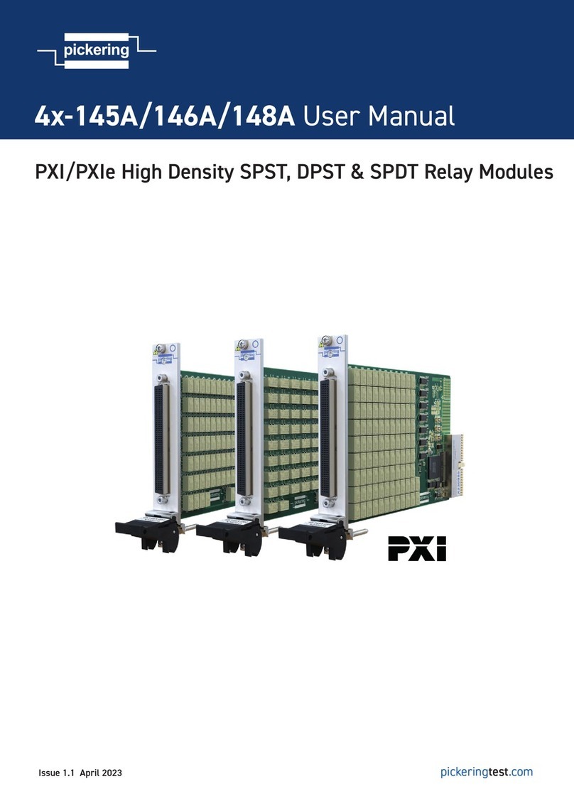
Pickering PXI 4 145A Series User manual

Pickering

Pickering PXI 4 145A Series User manual

Pickering 40-110 User manual

Pickering

Pickering 40-110 User manual

Pickering 40/42-139A User manual

Pickering

Pickering 40/42-139A User manual

Pickering PXI 40-131 User manual

Pickering

Pickering PXI 40-131 User manual

Pickering PXI 40-160 Series User manual

Pickering

Pickering PXI 40-160 Series User manual

Pickering 40-780B User manual

Pickering

Pickering 40-780B User manual

Pickering 40-153 User manual

Pickering

Pickering 40-153 User manual

Pickering PXI 40-780A User manual

Pickering

Pickering PXI 40-780A User manual

Pickering 50-131 User manual

Pickering

Pickering 50-131 User manual

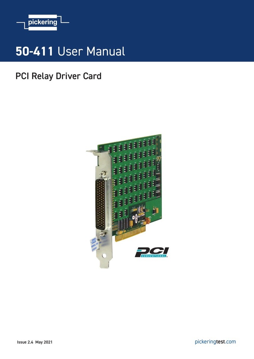
Pickering PCI 50-411 User manual

Pickering

Pickering PCI 50-411 User manual

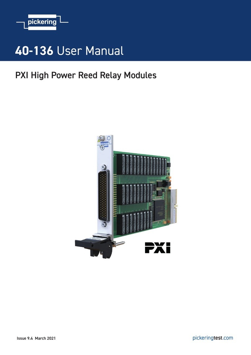
Pickering 40-136 User manual

Pickering

Pickering 40-136 User manual

Pickering SYSTEM 10 User manual

Pickering

Pickering SYSTEM 10 User manual

Pickering 40-138 User manual

Pickering

Pickering 40-138 User manual

Pickering 45-157 User manual

Pickering

Pickering 45-157 User manual

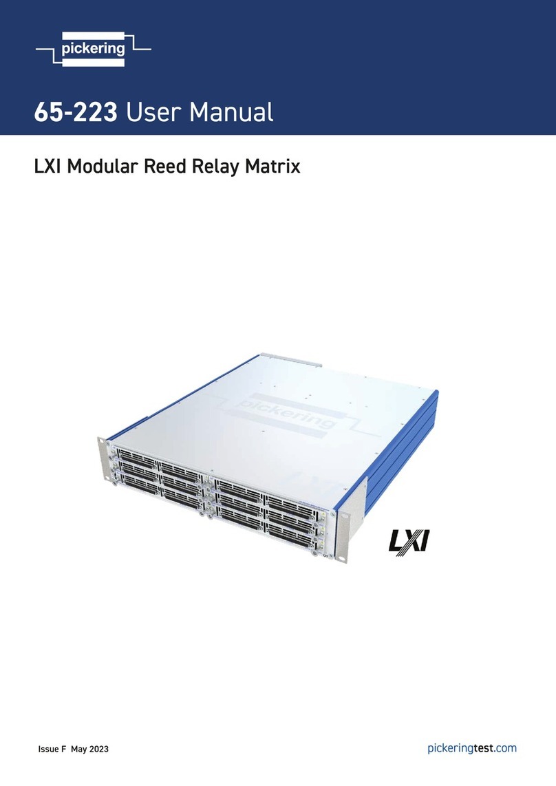
Pickering 65-223 User manual

Pickering

Pickering 65-223 User manual

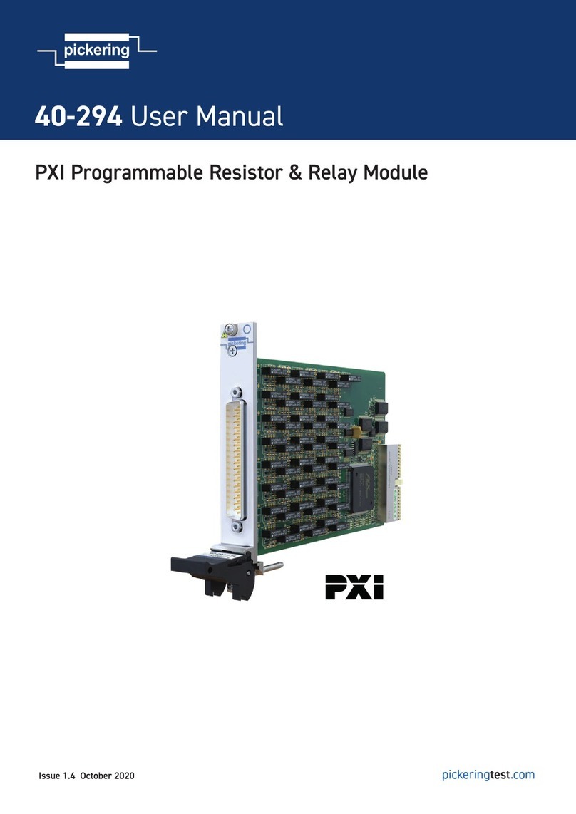
Pickering 40-294 User manual

Pickering

Pickering 40-294 User manual

Pickering 40-121 User manual

Pickering

Pickering 40-121 User manual

Pickering PXI 40-710 User manual

Pickering

Pickering PXI 40-710 User manual

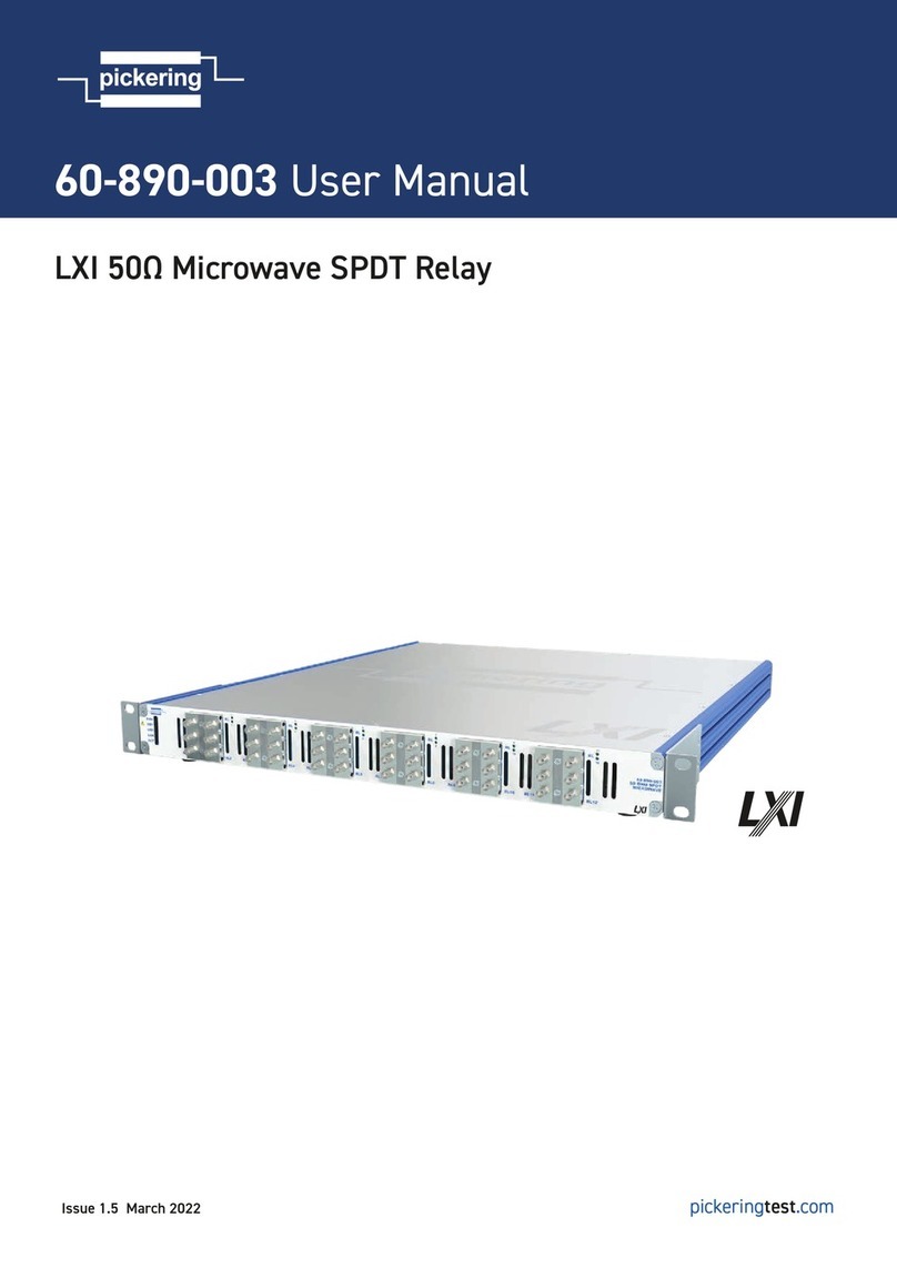
Pickering 60-890-003 User manual

Pickering

Pickering 60-890-003 User manual

Pickering 40-166 User manual

Pickering

Pickering 40-166 User manual

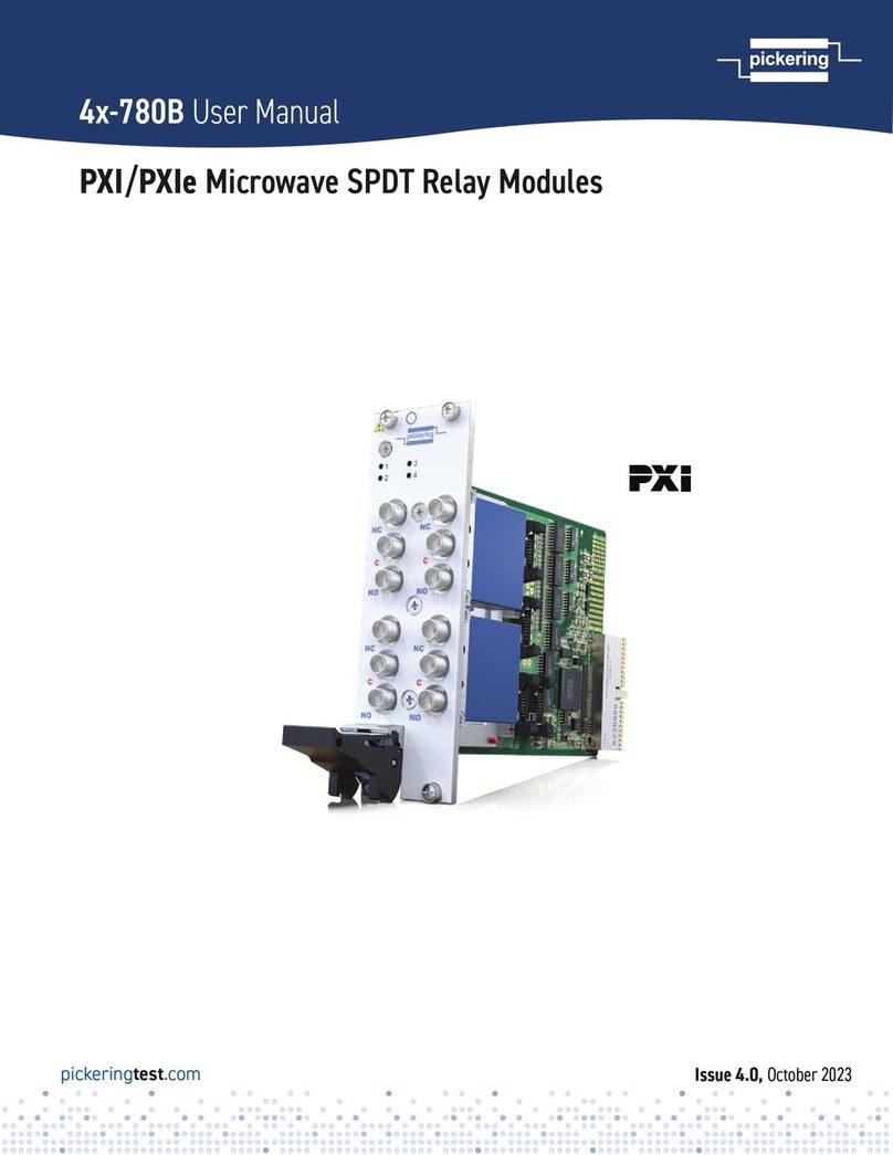
Pickering 4x-780B User manual

Pickering

Pickering 4x-780B User manual

Pickering 42-323 User manual

Pickering

Pickering 42-323 User manual

Popular Relay manuals by other brands

Chenzhu CZSR8401-1A user manual

Chenzhu

Chenzhu CZSR8401-1A user manual

LEGRAND LEXIC 26092 manual

LEGRAND

LEGRAND LEXIC 26092 manual

ABB E45 DU installation instructions

ABB

ABB E45 DU installation instructions

Aiphone RY-1824L instructions

Aiphone

Aiphone RY-1824L instructions

2N Helios IP Security Relay How to use

2N

2N Helios IP Security Relay How to use

Measurement Computing PCI-PDISO8 user guide

Measurement Computing

Measurement Computing PCI-PDISO8 user guide

Reer SR ONE Installation, use and maintenance

Reer

Reer SR ONE Installation, use and maintenance

GE B90 instruction manual

GE

GE B90 instruction manual

Pilz PNOZ X13 operating manual

Pilz

Pilz PNOZ X13 operating manual

ABB SPAU 140 C User manual and technical description

ABB

ABB SPAU 140 C User manual and technical description

ABB SPAS 348 C User manual and technical description

ABB

ABB SPAS 348 C User manual and technical description

Mitsubishi Electric MELPRO-A Series instruction manual

Mitsubishi Electric

Mitsubishi Electric MELPRO-A Series instruction manual

ABB SPACOM 300 operating guide

ABB

ABB SPACOM 300 operating guide

Siemens Sirius 3RS1440 operating instructions

Siemens

Siemens Sirius 3RS1440 operating instructions

Littelfuse 777 Series Wiring diagram

Littelfuse

Littelfuse 777 Series Wiring diagram

GE L90 instruction manual

GE

GE L90 instruction manual

Velleman VMA332 user manual

Velleman

Velleman VMA332 user manual

Schweitzer Engineering Laboratories SEL-787-2 manual

Schweitzer Engineering Laboratories

Schweitzer Engineering Laboratories SEL-787-2 manual

manuals.online logo
manuals.online logoBrands
  • About & Mission
  • Contact us
  • Privacy Policy
  • Terms and Conditions

Copyright 2025 Manuals.Online. All Rights Reserved.