Entes MCB-15 User manual
ZAMAN RÖLELERİ
MCB-15 Zaman Rölesi
TIME RELAYS
MCB-15 Time Relay
MCB-15 zaman rölesi 24-240 VAC/DC geniş besleme aralığı, 0.1
saniyeden 100 saate kadar ayarlanabilen zaman skalası ve 4 farklı
zaman fonksiyonu ile endüstriyel ve yerel uygulamalarda kullanılır.
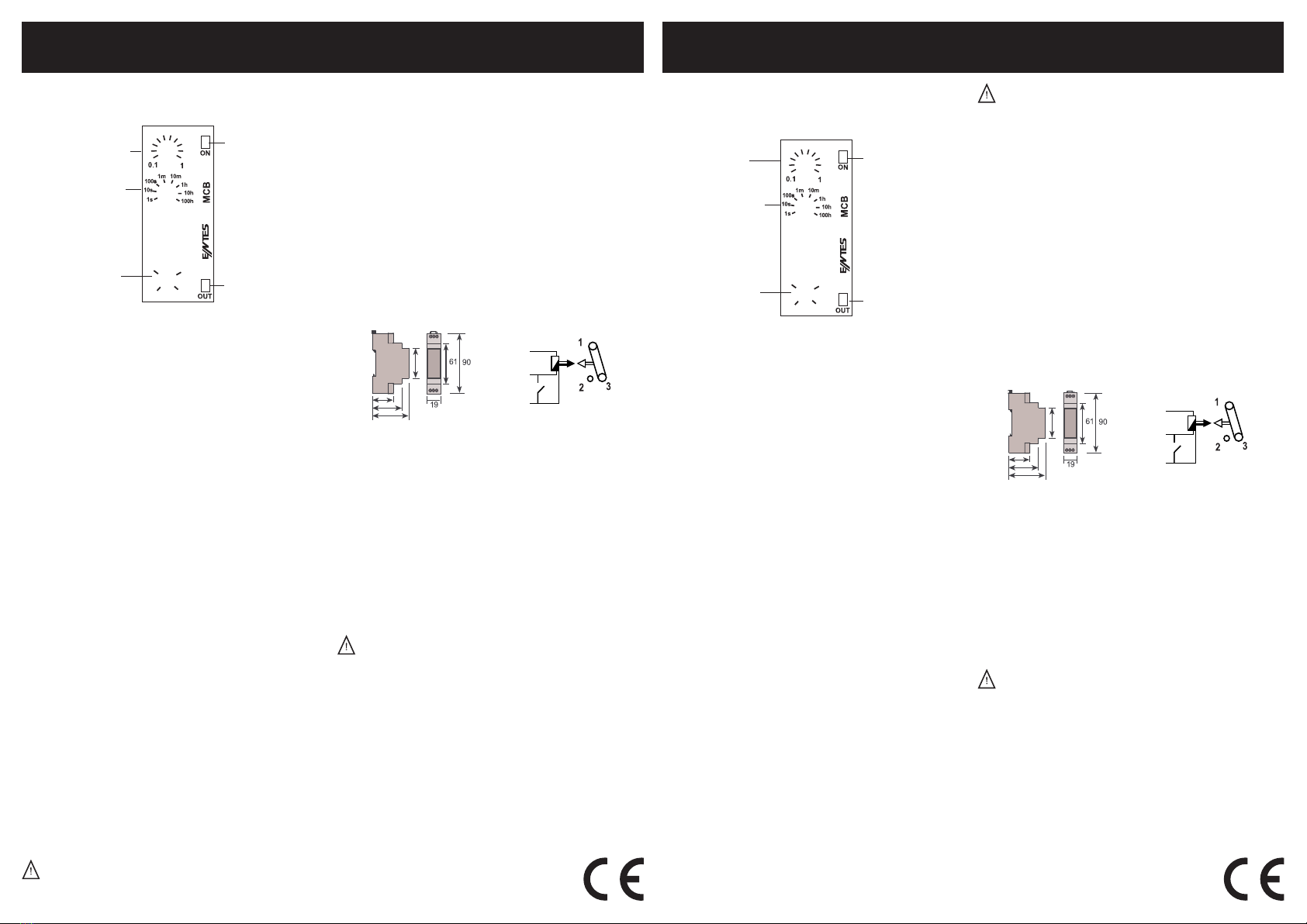
① Zaman Çarpanı Ayarı: Seçilen zaman diliminin çarpılacağı zaman
çarpanıdır. Cihaz üzerinde bulunan ayar trimpotu ile 0.1’den 1’e kadar
ayarlanır.
②Zaman Dilimi Ayarı: Seçilen zaman bölgesinin maksimum değerini
gösterir. Ayarlanmak istenen çalışma süresine göre 8 farklı zaman
diliminden seçim yapılır.
Çalışma süresi = Zaman dilimi x Zaman çarpanı
Örnek: Çalışma süresi 3 dakika olarak ayarlanmak isteniyorsa,
T = 10 x 0.3
T = 3 dakika
③Fonksiyon Ayarı: Cihazın çalışğı zaman fonksiyonu gösterir.
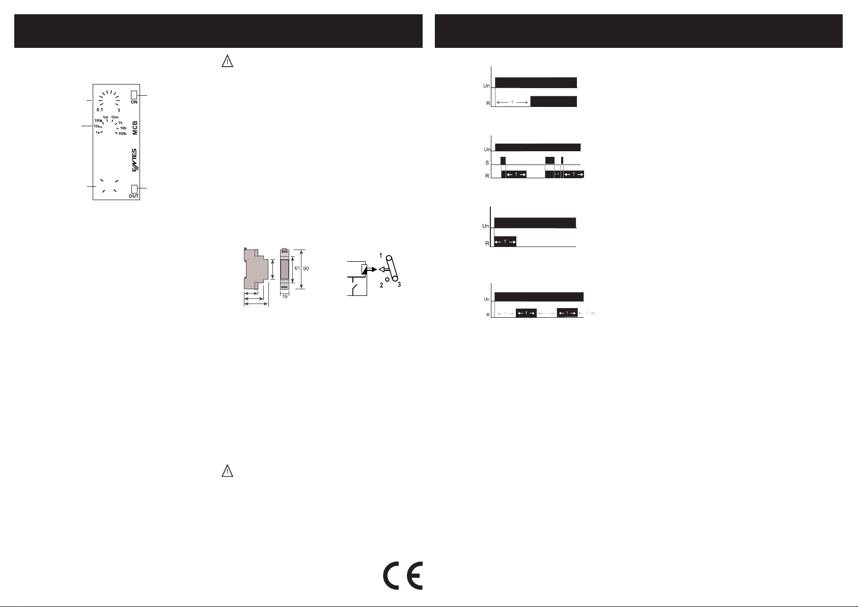
A Çekmede Gecikmeli: Besleme gerilimi uygulandığında ayarlanan t
bekleme süresi saymaya başlar. t süresinin bitmesinin ardından röle
çıkışı ON konumuna geçer. Cihazın besleme gerilimi kesilene kadar
röle çekili konumda kalır. t süresi bitmeden besleme gerilimi kesilirse,
sayılmış zaman silinir ve besleme gerilimi tekrar uygulandığında t
süresi tekrar saymaya başlar.
B Kontrol Girişli Bırakmada Gecikmeli: Besleme gerilimi ve tekleme
sinyali uygulandığında röle çeker. Tekleme sinyali kesildiğinde t
süresi saymaya başlar ve süre sonunda röle bırakır. t süresi bitmeden
tekrar sinyal uygulandığında sayılan süre silinir ve tekleme sinyalinin
kesilmesiyle birlikte yeniden saymaya başlar.
C Bırakmada Gecikmeli: Besleme gerilimi uygulandığında röle çeker
ve ayarlanan t süresi saymaya başlar. t süresi sonunda röle çıkışı
OFF konumuna geçer. Cihazın besleme gerilimi kesilene kadar röle
konumunu korur. t süresi bitmeden besleme gerilimi kesilirse sayılmış
zaman silinir ve besleme gerilimi tekrar uygulandığında t süresi tekrar
saymaya başlar.
D Simetrik Flaşör: Besleme gerilimi uygulandığında ayarlanan t süresi
saymaya başlar. t süresi sonundan röle çeker ve ayarlanan t süresi
tekrar saymaya başlar. Süre sonunda röle bırakır. Besleme gerilimi
kesilene kadar bu döngü devam eder.
Zaman diyagramları için sayfa 4 ‘e bakınız.
MCB-15 me relay uses in industrial and domesc applicaons with
24-240 VAC/DC wide operang range, adjustable me range from 0.1
seconds to 100 hours and 4 dierent ming funcons.
① Time Mulplier Adjustment: It is the me mulplier that the
selected me range is mulplied. It is set from 0.1 to 1 with the
adjustment trimpot on the device.
②Time Range Adjustment: It shows the maximum value of the
selected me range. One of 8 dierent me range is selected
according to the operaon me to be set.
Operaon me = Time range x Time mulplier
Example: If it is wanted to be set operaon me to 3 minutes
T = 10 x 0.3
T = 3 min
③Funcon Adjustment: It shows the funcon of the device.
A ON Delay: When the supply voltage is applied, the adjusted me t
is started to count. Aer the adjusted t has expired, the output relay
switches into ON posion. This status remains unl the supply voltage
is interrupted. If the supply voltage is interrupted before the expiry of
the adjusted me, the me already expired is erased and is restarted
when the supply voltage is applied again.
B OFF Delay with Control Input: When the supply voltage and
the triggering signal are applied, the output relay switches into ON
posion. When the triggering signal is interrupted, the me t is started
to count and the output relay switches into OFF posion at the end of
the me. If the triggering signal is applied again before the me t has
expired, the me already expired is erased. The me restarts again
when the triggering signal is interrupted.
C OFF Delay: When the supply voltage is applied, the output relay
switches into ON posion and the adjusted me t is started to count.
The output relay switches into OFF posion at the end of the me t.
This status remains unl the supply voltage is interrupted. If the supply
voltage is interrupted before the expiry of the adjusted me, the me
already expired is erased and is restarted when the supply voltage is
applied again.
D Symmetric Flasher: When the supply voltage is applied, the
adjusted me t is started to count. The output relay switches into ON
posion at the end of the me t and the adjusted me counts again.
The output relay switches into OFF posion at the end of the me t.
This cycle counnues ll the supply voltage is interrupted.
A8246/Rev.2 A8246/Rev.2
④Besleme ışığı: Besleme gerilimi uygulandığında cihaz üzerindeki
ON LED’i yanar. Besleme gerilimi kesildiğinde ON LED’i söner.
⑤Röle ışığı: Röle çekili konumdayken cihaz üzerindeki OUT LED’i
yanar. Röle kontağını bırakğında OUT LED’i söner.
Teknik Bilgi
Işletme Gerilimi (Un) : 24 – 240 VAC/DC
İşletme Frekansı : 50/60 Hz
Çıkış Kontağı : 1 CO, 8 A, 2000 VA (cosϕ=1)
Zaman Aralığı : 0.1 sn – 100 saat
Ortam Sıcaklığı : -5 °C / + 50 °C
Koruma Sını : IP20
Boyutlar : Tip PK 22
Bağlan Şekli : Pano içine dikey veya klemens rayına
Ağırlık : 60 gr
Boyutlar Bağlan Şeması
Güvenli Kullanım ve Kurulum İçin Uyarılar
Aşağıdaki talimatlara uyulmaması halinde yaralanma ve ölümle
sonuçlanabilecek durumlar ortaya çıkabilir.
• Cihaz üzerindeki herhangi bir işlemden önce tüm besleme
gerilimlerini kesiniz.
• Cihaz şebekeye bağlı iken ön paneli çıkarmayınız.
• Cihazı solvent veya benzeri maddelerle temizlemeyiniz. Cihazı
temizlemek için sadece kuru bez kullanınız.
• Cihazı çalışrmadan önce bağlanlarının doğru olduğunu
kontrol ediniz.
• Cihazınızdaki herhangi bir sorunda yetkili sacınızla temas kurunuz.
• Cihazı panoya monte ediniz.
Yukarıdaki önlemlerin uygulanmaması sonucu doğabilecek
istenmeyen durumlardan üreci rma hiç bir şekilde sorumlu
tutulamaz.
Not: Kontak dayanımı omik yükte (ör = Akkor emanlı ampul, Rezistanslı
cihazlar) 8A’dir. Endükf (ör = AC motor, orasan (Sargılı balaslı), vb..)
ya da Kapasif (ör = Led Sürücüler, UPS, orasan(Elektronik Balastlı),
vb..) yük anahtarlanacaksa kontaktör kullanılması tavsiye edilir. Aksi
takrde cihazın röle kontaklarında yapışma meydana gelebilir.
Bu ürün, 30.05.2008 tarih ve 26891 sayılı resmi gazetede yayınlanan
EEE Yönetmeliğinin Madde 2 ve Ek-1A madde 9 kapsamındadır.
Please, see the page 4 for me diagrams.
④Supply LED: When the supply voltage is applied, ON LED on the
device illuminates. When the supply voltage is interrupted, ON LED
exnguishes.
⑤Relay LED: When the output relay is ON posion, OUT LED on the
device illuminates. When the output relay is OFF posion, OUT LED
exnguishes.
Technical Data
Rated Voltage (Un) : 24 – 240 VAC/DC
Rated Frequency : 50/60 Hz
Output Contacts : 1 CO, 8 A, 2000 VA (cosϕ=1)
Delay Time : 0.1 sec – 100 hours
Ambient Temperature : -5 °C / + 50 °C
Protecon Class : IP20
Dimensions : Type PK 22
Installaon : Surface mounng or on the mounng rails
Weight : 60 gr
Dimensions Connecon Diagram
Precauons for Installaon and Safe Use
Failure to follow those instrucons will result in death or serious injury.
• Disconnect all power before working on equipment.
• When the device is connected to the network, do not remove the
front panel.
• Do not clean the device with solvent or the like. Only clean the
device with a dried cloth.
• Verify correct terminal connecon when wiring.
• Electrical equipment should be serviced only by your competent
seller.
• Mount device to panel.
No responsibility is assured by the manufacturer or any its
subsidiaries for any consequences arising out the use of this
material.
Note: The contact resistance at ohmic load (e.g.: Incandescent bulb,
Resistance devices) is 8A. It is recommended to use a contactor if the
inducve load (e.g.: AC motor, uorescent, etc.) or capacive load
(e.g. : Led Drivers, UPS, Fluorescent(Electronic Ballast), etc.) switch.
Otherwise adhesion may occur in relay contacts.
A
B
C
D
-15
A
B
C
D
-15
① Zaman çarpanı
ayarı ①
Time Mulplier
Adjustment
② Zaman dilimi
ayarı ② Time Range
Adjustment
③ Fonksiyon ayarı
③ Funcon
Adjustment
④Besleme ışığı
④ Supply LED
⑤Röle ışığı
⑤ Relay LED
A1
B1
24-240
VAC/DC
A2
27,5
45,6
58
48
A1
B1
24-240
VAC/DC
A2
27,5
45,6
58
48
Das Zeitrelais MCB-15 wird in industriellen und lokalen Anwendungen
mit breitem Betriebsbereich von 24-240 VAC/DC, einstellbarem
Zeitskala von 0,1 Sekunden bis 100 Stunden und 4 verschiedenen
Zeiunkonen eingesetzt
① Zeiaktoreinstellung: Faktor, das mit der gewählten Zeitperiode
mulpliziert wird. Kann mit dem Trmpot auf dem Gerät zwischen 0.1
und 1 eingestellt werden.
②Einstellung der Zeitperiode: Zeigt den Höchstwert der gewählten
Zeitbereich. Anhand der gewünschten Betriebszeit, kann es in 8
unterschiedlichen Zeitperioden ausgewählt werden.
Betriebszeit = Zeitperiode x Zeiaktor
Beispiel: Wenn die Betriebszeit auf 3 Minuten eingestellt werden soll,
T = 10 x 0.3
T = 3 Minuten
③Funkonseinstellung: Zeigt die eingestellte Zeiunkon.
A Einschaltverzögerung: Mit dem Anlegen der Versorgungsspannung
beginnt die eingestellte Zeit t zu laufen. Nach Ablauf der Zeit
t zieht das Ausgangsrelais an. Dieser Zustand bleibt aufrecht,
bis die Versorgungsspannung unterbrochen wird. Wird die
Versorgungsspannung vor Ablauf der Zeit t unterbrochen, wird die
bereits abgelaufene Zeit gelöscht und mit dem nächsten Anlegen der
Versorgungsspannung erneut gestartet.
B Ausschaltverzögerung mit Steuerungseingang: Mit der Vorhanden
der Versorgungsspannung und Schließen des Steuerkontaktes
zieht das Ausgangsrelais an. Mit dem Önen des Steuerkontakts
beginnt die eingestellte Zeit t zu laufen und nach dieser Zeit wird der
Ausgansrelais geönet. Wenn das Steuersignal vor dem Ende der
Zeit t erneut anliegt, wird die gezählte Zeit gelöscht und die Zählung
beginnt erneut mit dem Beenden des Steuersignals.
C Ausschaltverzögerung: Mit dem Anlegen der Versorgungsspannung
zieht das Ausgangsrelais an und die eingestellte Zeit t beginnt zu laufen.
Nach Ablauf der Zeit t fällt das Ausgangsrelais ab. Dieser Zustand
bleibt aufrecht, bis die Versorgungsspannung unterbrochen wird. Wird
die Versorgungsspannung vor Ablauf der Zeit t unterbrochen, fällt das
Ausgangsrelais ab. Die bereits abgelaufene Zeit wird gelöscht und mit
dem nächsten Anlegen der Versorgungsspannung erneut gestartet.
D Symmetrischer Blinker: Mit dem Anlegen der Versorgungsspannung
beginnt die eingestellte Zeit t zu laufen. Nach Ablauf der Zeit t wird
das Ausgangsrelais eingeschaltet und unmielbar nach Ablauf der
gleichen Zeit t wird das Ausgangsrelais wieder ausgeschaltet. Dieser
Zyklus wird fortgesetzt, bis die Versorgungsspannung unterbrochen
wird.
Zeitdiagramme nden Sie auf Seite 4.
④Versorgungs-LED: Falls MCB-15 versorgt wird, wird die ON-LED auf
dem Gerät eingeschaltet. Wenn die Versorgungsspannung verhindert
wird, wird der ON-LED ausgeschaltet.
⑤Relaisstatus-LED: OUT-LED wird eingeschaltet, wenn das Relais
eingeschaltet ist. OUT-LED wird ausgeschaltet, wenn das Relais
ausgeschaltet ist.
Technische Daten
Betriebsspannung (Un) : 24 – 240 VAC/DC
Betriebsfrequenz : 50/60 Hz
Ausgangskontakt : 1 Wechsler, 8 A, 2000 VA (cosϕ=1)
Zeitbereich : 0,1 s – 100 h
Umgebungstemperatur : -5 bis +50 °C
Schutzklasse : IP20
Abmessungen : Typ PK 22
Installaon :
Oberächenmontage oder an Montageschienen
Gewicht : 60 gr
Abmessungen Ansclussdiagramm
Warnhinweise zu Installaon und Sicherer Benutzung
Bei Nichtbeachtung dieser Anweisungen drohen ernsthae oder sogar
tödliche Verletzungen.
• Trennen Sie die gesamte Stromversorgung vor Arbeiten am Gerät
• Während das Gerät mit dem Netzwerk verbunden ist, dürfen Sie
die Frontplae nicht enernen.
• Versuchen Sie nicht, das Gerät mit Lösungsmiel oder dergleichen
zu reinigen. Reinigen Sie das Gerät nur mit einem weichen Tuch.
• Achten Sie beim Anschließen auf die Ausführung korrekter Verbind
ungen.
• Elektrische Geräte sollten nur vom jeweiligen Händler gewartet
werden.
• Moneren Sie das Gerät auf die Hutschiene in der Schalafel.
Der Hersteller und seine Vertriebspartner übernehmen
keinerlei Haung für Vorfälle jeglicher Art in Zusammenhang
mit diesem Material.
Hinweis: Der Kontaktwiderstand bei ohmscher Last (z. B. Glühlampe,
Widerstände) beträgt 8A. Sie sollten einen Schütz verwenden, wenn
die indukve Last (z. B. Wechselstrommotor, Leuchtstoampe
usw.) oder kapazive Last (z. B. LED-Treiber, USV, Leuchtstoampe
(elektronisches Vorschaltgerät) usw.) wechselt. Andernfalls kann eine
Adhäsion in den Relaiskontakten aureten.
A
B
C
D
-15
①
Zeiaktoreinstellung
② Einstellung der
Zeitperiode
③ Funkonseinstellung
④ Versorgungs-LED
⑤ Relaisstatus-LED
A8246/Rev.2
A Fonksiyonu / A Funcon / A Funkon
B Fonksiyonu / B Funcon / B Funkon
C Fonksiyonu / C Funcon / C Funkon
D Fonksiyonu / D Funcon / D Funkon
ENTES Elektronik Cihazlar Imalat ve Ticaret A.S.
Adr : Dudullu OSB, 1. Cadde, No:23, 34776
Umraniye- Istanbul / TURKEY
Tel : +90 (216) 313 0110
Fax : +90 (216) 314 1615
Web : www.entes.com.tr
ZEITRELAIS
MCB-15 Zeitrelais
ZAMAN DİYAGRAMLARI /
TIME DIAGRAMS/ ZEITDIAGRAMME
A1
B1
24-240
VAC/DC
A2
27,5
45,6
58
48
Other Entes Relay manuals


Popular Relay manuals by other brands

Rockwell Automation
Rockwell Automation Allen-Bradley Guardmaster MSR55P installation instructions

Ghisalba
Ghisalba GH44B operating instructions

GE
GE IBCG51E21 instructions

Eaton
Eaton DILH1200/22 Instruction leaflet

Simplex
Simplex 4090-9118 installation instructions

Plejd
Plejd DIM-01-2P installation manual


