CARLO GAVAZZI DPC01 User manual

Description
DPC01 and PPC01 are 3-phase mains monitoring
relays.
They operate on 3P and 3P+N systems,
monitoring phase loss and phase sequence,
overvoltage and undervoltage, voltage asymmetry
and tolerance.
Power supply provided by the monitored mains.
Two independent delay functions, up to 30 s, for
over / under voltage and asymmetry / tolerance
alarms.
Benefits
•Wide voltages and frequency ranges. Working in
systems from 100 to 690 VAC and 50 to 400 Hz.
•Adjustable voltage levels, asymmetry, tolerance
and time delay. To allow a correct response to real
alarm conditions.
•Output and status LED indication. For quick
troubleshooting.
•Two mounting versions. Available for DIN-rail
(DPC01) and Plug-in (PPC01) mounting.
•Adjustable power ON delay. To avoid nuisance
tripping at start-up.
•Ultra-high harmonic immunity. For very noisy
environments.
Main features
•Monitoring 3-phase mains with 3 wires (3P) or 4 wires (3P+N).
•Detection of the correct phase sequence, phase loss, asymmetry and tolerance.
•Front dial adjustable overvoltage, undervoltage, asymmetry and tolerance setpoints.
•Time delay.
•Two changeover relay outputs.
14/10/2022 DPC01_PPC01_DS_ENG Carlo Gavazzi Controls S.p.A. 1
DPC01, PPC01
True RMS 3-Phase voltage monitoring relay

14/10/2022 DPC01_PPC01_DS_ENG Carlo Gavazzi Controls S.p.A. 2
DPC01, PPC01
Order code
Mounting Frequency Power supply Component name/part number
DIN-rail
50 - 400 Hz 100 to 115 VAC DPC01DM11400HZ
50 - 60 Hz 208 to 240 VAC DPC01DM23
50 - 400 Hz DPC01DM23400HZ
50 - 400 Hz 208 to 690 VAC DPC01DM44
50 - 60 Hz 380 to 480 VAC DPC01DM48
50 - 400 Hz 380 to 415 VAC DPC01DM48400HZ
440 to 480 VAC DPC01DM49400HZ
50 - 60 Hz 600 to 690 VAC DPC01DM69
50 - 400 Hz DPC01DM69400HZ
Plug-in 50 - 60 Hz 208 to 240 VAC PPC01DM23
380 to 415 VAC PPC01DM48
Structure
DPC01 PPC01
Element Component Function
AInput terminals Connection of the line voltages (neutral when present)
BInformation LEDs
Yellow for relay output status
Red for signal alarm status
Green for device ON
CDIP switches Setting the nominal voltage, type of mains, power ON delay
DOutput terminals 2 x SPDT relay outputs

14/10/2022 DPC01_PPC01_DS_ENG Carlo Gavazzi Controls S.p.A. 3
DPC01, PPC01
Element Component Function
EOvervoltage ( ) / asymmetry (ASY) dial Overvoltage / asymmetry setpoint adjustment
FUndervoltage ( ) / tolerance ( ) dial Undervoltage / tolerance setpoint adjustment
GDelay time dials Setting the alarm ON delay time
Features
Power supply
Power supply Supplied by measured phases (L1, L2, L3)
Overvoltage category III (IEC 60664)
Voltage range
DPC01DM11400HZ 110 to 115 VL-L AC ± 15% (85 to 132 V)
DPC01DM23
DPC01DM23400HZ
PPC01DM23
208 to 240 VL-L AC ± 15% (177 to 276 V)
DPC01DM44 208 to 690 VL-L AC ± 15% (177 to 793 V)
DPC01DM48 380 to 480 VL-L AC ± 15% (323V to 552 V)
DPC01DM48400HZ
PPC01DM48 380 to 415 VL-L AC ± 15% (323 to 477 V)
DPC01DM49400HZ 440 to 480 VL-L AC ± 15% (374V to 552 V)
DPC01DM69
DPC01DM69400HZ 600 to 690 VL-L AC ± 15% (510 to 793 V)
Frequency range 50 to 60 Hz ± 10% sinusoidal waveform
M44 and 400 Hz only: 50 to 400 Hz ± 10% sinusoidal waveform
Consumption
DPC01DM11400HZ < 1.5 VA
DPC01DM23
DPC01DM23400HZ
PPC01DM23
< 2.5 VA
DPC01DM44 < 4.5 VA
DPC01DM48
DPC01DM48400HZ
PPC01DM48
DPC01DM49400HZ
< 3.5 VA
DPC01DM69
DPC01DM69400HZ < 7 VA
Power ON delay 1 s ± 0.5 s or 6 s ± 0.5 s

14/10/2022 DPC01_PPC01_DS_ENG Carlo Gavazzi Controls S.p.A. 4
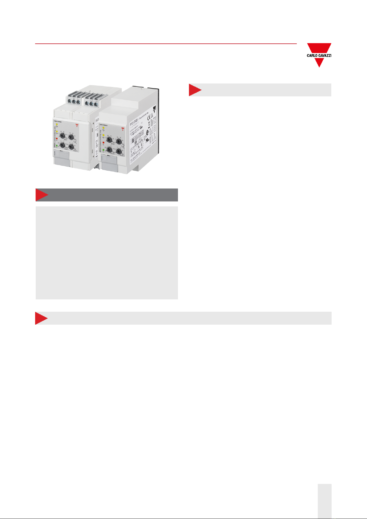
DPC01, PPC01
Inputs
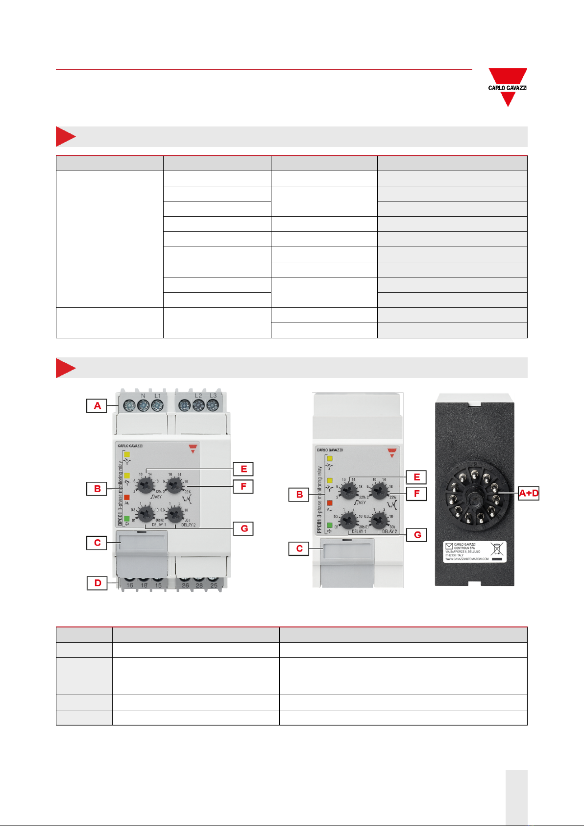
Terminals DPC01: L1, L2, L3, N
PPC01: 5, 6, 7, 11
Measured variables
Phase sequence
Phase loss
Asymmetry
Tolerance
3P: voltages VL12, VL23, VL31
3P+N: voltages VL1N, VL2N, VL3N
Nominal line range 100 to 690 VAC ± 15% (85 to 793 VAC)
Nominal
voltages (*)
DPC01DM11400HZ
Delta voltage (3P) 100 V, 115 V
Star voltage (3P+N) 58 V, 66 V
DPC01DM23
DPC01DM23400HZ
PPC01DM23
Delta voltage (3P) 208 V, 220 V, 230 V, 240 V
Star voltage (3P+N) 120 V, 127 V, 133 V, 140 V
DPC01CM44
Delta voltage (3P) 208 V, 220 V, 230 V, 240 V, 380 V, 400 V, 415 V, 440 V,
480 V, 600 V, 690 V
Star voltage (3P+N) 120 V, 127 V, 133 V, 140 V, 220 V, 230 V, 240 V, 254 V,
277 V, 347 V, 400 V
DPC01CM48
Delta voltage (3P) 380 V, 400 V, 415 V, 480 V
Star voltage (3P+N) 220 V, 230 V, 240 V, 277 V
DPC01CM48400HZ
PPC01CM48
Delta voltage (3P) 380 V, 400 V, 415 V
Star voltage (3P+N) 220 V, 230 V, 240 V
DPC01DM49400HZ
Delta voltage (3P) 440 V, 480 V
Star voltage (3P+N) 254 V, 277 V
DPC01DM69
DPC01DM69400HZ
Delta voltage (3P) 600 V, 690 V
Star voltage (3P+N) 347 V, 400 V
(*) Note: connect the neutral only if it is intrinsically at the star centre.

14/10/2022 DPC01_PPC01_DS_ENG Carlo Gavazzi Controls S.p.A. 5
DPC01, PPC01
Outputs
Terminals DPC01: 15, 16, 18, 25, 26, 28
PPC01: 1, 3, 4, 8, 9, 10
Number of outputs 2
Type SPDT electromechanical relay with changeover contacts
Logic Output de-energised on alarm
Contact rating
Ith: 8 A @ 250 VAC
AC15: 2.5 A @ 250 VAC
DC12: 5 A @ 24 VDC
DC13: 2.5 A @ 24 VDC
Electrical lifetime ≥50 x 103operations (at 8 A, 250 V, cos φ= 1)
Mechanical lifetime >30 x 106operations
Assignment
2 x SPDT:
Output 1: overvoltage or asymmetry
Output 2: undervoltage or tolerance
1 x DPDT:
Output 1 and 2: any alarm
Insulation
Terminals Basic
Inputs: L1, L2, L3, N (DPC01) / 5, 6, 7, 11 (PPC01)
to
outputs: 15, 16, 18, 25, 26, 28 (DPC01) / 1, 3, 4, 8, 9, 10 (PPC01)
2.5 kVrms, 4 kV impulse 1.2/50 μs
General
Material Polyamide (Nylon) (PA66/6) or Phenylene ether + Polystyrene (PPE-PS)
Flammability rating: HB according to UL 94
Colour RAL7035 (light grey)
Dimensions (W x H x D) DPC01: 45 x 80 x 99.5 mm (1.77 x 3.15 x 3.92 in)
PPC01: 36 x 80 x 94 mm (1.42 x 3.15 x 3.7 in)
Weight 150 g (5.29 oz)
Terminals Cable size from 0.05 to 2.5 mm2(AWG30 to AWG13), stranded or solid
Tightening torque Max. 0.5 Nm (4.425 lbin)
Terminal type Double cage screw terminals (DPC01), Undecal Plug-in terminals (PPC01)

14/10/2022 DPC01_PPC01_DS_ENG Carlo Gavazzi Controls S.p.A. 6
DPC01, PPC01
DIN-rail Plug-in
Environmental
Operating temperature -20 to 60 °C (-4 to 140 °F)
Storage temperature -30 to 80 °C (-22 to 176 °F)
Relative humidity 5 - 95% non condensing
Protection degree IP20
Pollution degree 2
Operating max altitude 2000 m amsl (6560 ft)
Salinity Non saline environment
UV resistance No
Vibration/Shock resistance
Test condition Test Level
Tests with unpacked device
Vibration response (IEC60255-21-1) Class 1
Vibration endurance (IEC 60255-21-1) Class 1
Shock (IEC 60255-21-2) Class 1
Bump (IEC 60255-21-2) Class 1
Tests with packed device
Vibration random (IEC60068-2-64) Class 1
Shock (IEC 60255-21-2) Class 1
Bump (IEC 60255-21-2) Class 1
Class 1: monitoring devices for normal use in power plants, substations and industrial plants and for normal
transportation conditions.
The packaging type is designed and implemented in such manner that the severity class parameters will not be
exceeded during transportation.

14/10/2022 DPC01_PPC01_DS_ENG Carlo Gavazzi Controls S.p.A. 7
DPC01, PPC01
Compatibility and conformity
Marking
Directives 2014/35/EU (LVD - Low voltage)
2014/30/EU (EMC - Electromagnetic compatibility)
Standards
Insulation coordination: EN 60664-1
Immunity: EN61000-6-2
Emission: EN61000-6-3
Approvals
DPC01
(UL508, UL61010) (GB/T14048.5) DPC01 only
PPC01
Operating description
DIP switches
Typology
DPC01DM44 6 + 2 switches (Fig.1)
DPC01DM11400HZ
DPC01DM23/400HZ
PPC01DM23
DPC01DM48/400HZ
PPC01DM48
DPC01DM49400HZ
DPC01DM69/400HZ
6 switches (Fig. 2, 3, 4, 5 and 6)
Function
Power ON delay
Mains type
Mains voltage (M44: 11 ranges; M11, M23, M48, M49 and M69: 4 ranges)
Output configuration
Operating function

14/10/2022 DPC01_PPC01_DS_ENG Carlo Gavazzi Controls S.p.A. 8
DPC01, PPC01
Fig. 1 DIP switch settings M44 Fig. 2 DIP switch settings M11
Fig. 3 DIP switch settings M23 Fig. 4 DIP switch settings M48
Fig. 5 DIP switch settings M49 Fig. 6 DIP switch settings M69

14/10/2022 DPC01_PPC01_DS_ENG Carlo Gavazzi Controls S.p.A. 9
DPC01, PPC01
Device configuration
The relay operates when all the phases are present, the phase sequence is correct and the input voltage levels
are within set limits.
Delay on alarm is configurable by front dials, each one of the two alarms (undervoltage / overvoltage or
asymmetry / tolerance) can be set with individual delay.
Asymmetry is an indicator of the mains quality and it is defined as the absolute value of the maximum deviation
among the mains voltages, divided by the nominal voltage of the 3-phase system. The definition changes
according to the voltage reference:
Main type Voltage asymmetry (%)
3P
3P+N
Phase-phase monitoring Phase-neutral monitoring
Tolerance is another indicator of the mains quality and it is defined as the absolute value of the maximum
deviation of the mains voltages from the nominal voltage, divided by the nominal voltage of the 3-phase
system. The definition changes according to the voltage reference:
Main type Voltage tolerance (%)
3P
3P+N

14/10/2022 DPC01_PPC01_DS_ENG Carlo Gavazzi Controls S.p.A. 10
DPC01, PPC01
Phase-phase monitoring Phase-neutral monitoring
Overvoltage / asymmetry adjustment dial
Typology Linear selection from 2 to 22%
Resolution 2% setpoint increase per notch
Function Asymmetry setpoint
Undervoltage / tolerance adjustment dial
Typology Linear selection from 2 to 22%
Resolution 2% setpoint increase per notch
Function Asymmetry setpoint
Delay 1 setting dial
Typology Logarithmic adjustment from 0.1 to 30 s
Resolution From 100 ms/notch at 0.1 s to 10 s/notch at 30 s
Function Alarm ON delay setting for overvoltage or asymmetry
Delay 2 setting dial
Typology Logarithmic adjustment from 0.1 to 30 s
Resolution From 100 ms/notch at 0.1 s to 10 s/notch at 30 s
Function Alarm ON delay setting for undervoltage or tolerance

14/10/2022 DPC01_PPC01_DS_ENG Carlo Gavazzi Controls S.p.A. 11
DPC01, PPC01
Alarms
DPC01 and PPC01 operate in 3 different modes depending upon the alarm type:
•Phase loss and incorrect phase sequence cause immediate output relays 1 and 2 de-energisation.
•Overvoltage or asymmetry triggering cause output 1 relay to turn OFF at the end of the set delay on alarm 1.
•Undervoltage or out of tolerance triggering cause output 2 relay to turn OFF at the end of the set delay on
alarm 2.
Phase loss alarm
Input variables L1-L2, L2-L3 and L3-L1
Alarm setpoint One phase ≤ 85% of the rated value (regenerated voltage detection)
Restore setpoint All phases > 85% of the rated value + Hysteresis
Reaction time ≤ 200 ms
Hysteresis 2% fixed
Delay ON None
Delay OFF None
Phase sequence alarm
Input variables Connection L1, L2, L3
Reaction time ≤ 200 ms
Delay ON None
Delay OFF None
Over or asymmetry voltage/ under or tolerance voltage alarms
Input variables 3P: voltages VL12, VL23, VL31
3P+N: voltages VL1N, VL2N, VL3N
Reaction time ≤ 200 ms + set delay ON alarm
Undervoltage setting range From -2 to -22%
Overvoltage setting range From 2 to 22%
Asymmetry setting range From 2 to 22%
Tolerance setting range From ± 2% to ± 22%
Repeatability 0.5% reading
Hysteresis Setpoint between 2% and 5% → Hys 1%
Setpoint between 5% and 22% → Hys 2%
Delay ON
Adjustable: from 0.1 to 30 s
Accuracy: from ± 50 ms at 0.1 s to ± 5 s at 30 s
Repeatability: from ± 10 ms at 0.1 s to ± 1 s at 30 s
Delay OFF None

14/10/2022 DPC01_PPC01_DS_ENG Carlo Gavazzi Controls S.p.A. 12
DPC01, PPC01
Information LEDs
Colour Status Description
Green ( ) Power supply ON Power supply ON
OFF Power supply OFF
Red (AL) Alarm
ON (steady) Alarm situation is still present at the end of delay
OFF Alarm OFF
Flashing 2 Hz Under / overvoltage or asymmetry / tolerance alarm
triggered with a delay on alarm elapsing
Flashing 5 Hz Phase loss or incorrect phase sequence alarm
Yellow ( ) Relay output ON Energised
OFF De-energised
Yellow ( ) Relay output ON Energised
OFF De-energised
NOTE: DPC01DM11400HZ, DPC01DM23400HZ, DPC01DM48400HZ, DPC01DM49400HZ,
DPC01DM69400HZ feature 3 front LEDs, (power supply) and AL (alarm) in the same LED.
Operating diagram
Over and undervoltage monitoring (2 x SPDT relays)

14/10/2022 DPC01_PPC01_DS_ENG Carlo Gavazzi Controls S.p.A. 13
DPC01, PPC01
Total phase loss, phase sequence

14/10/2022 DPC01_PPC01_DS_ENG Carlo Gavazzi Controls S.p.A. 14
DPC01, PPC01
Asymmetry and tolerance monitoring (2 x SPDT relays)
(*) M44 and 400HZ versions:
- flashing "Red-Green LED" during time delay
- "Red LED" steady in alarm condition

14/10/2022 DPC01_PPC01_DS_ENG Carlo Gavazzi Controls S.p.A. 15
DPC01, PPC01
Connection diagrams
(*) NOTE: fuses F of 315 mA delayed, if required by local law.
DPC01 PPC01
References
Further reading
Information Document Where to find it
Installation
manual
xPC01DMxx_
IM.pdf http://gavazziautomation.com/images/PIM/MANUALS/ENG/xPC01DMxx IM.pdf
DPC01CM44_
IM.pdf http://gavazziautomation.com/images/PIM/MANUALS/ENG/DPC01DM44_IM.pdf
COPYRIGHT ©2022
Content subject to change. Download the PDF: www.productselection.net
This manual suits for next models
11
Table of contents
Other CARLO GAVAZZI Relay manuals

CARLO GAVAZZI
CARLO GAVAZZI DWB02 User manual

CARLO GAVAZZI
CARLO GAVAZZI DPD02DM44B User manual

CARLO GAVAZZI
CARLO GAVAZZI DWB03 User manual

CARLO GAVAZZI
CARLO GAVAZZI RG Series User manual

CARLO GAVAZZI
CARLO GAVAZZI RGC1A User manual

CARLO GAVAZZI
CARLO GAVAZZI D/P PB01CM23/N User manual

CARLO GAVAZZI
CARLO GAVAZZI BTM-T15-PLUS User manual

CARLO GAVAZZI
CARLO GAVAZZI DTA71CM24 Instruction manual

CARLO GAVAZZI
CARLO GAVAZZI DPB01 User manual

CARLO GAVAZZI
CARLO GAVAZZI DIB01CB23 User manual