FIELD
CALIBRATION
PROCEDURE
NO.
322-0300
82 E Main Sreet Suite 3.14
Webster New York 14580
Phone:
(585) 872-9350
Fax:
(585) 872-2638
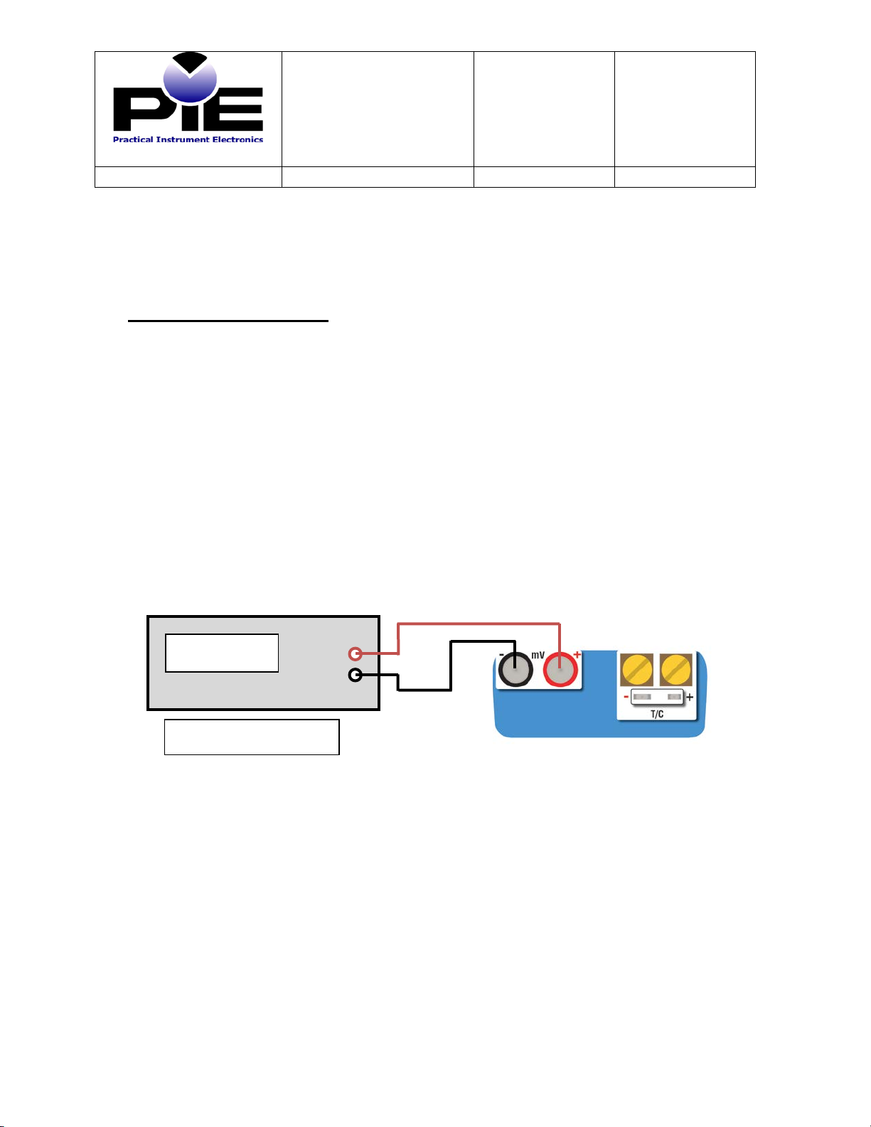
Thermocouple Cold Junction Temperature & LCD Contrast
Important! The cold junction sensor is a NIST traceable thermistor that is accurate to ±0.05°C
for 10 years. There should not be any need to perform the following adjustments. Perform this
calibration ONLY if you require repeatability of the UUC to match other temperature device
calibrated in your laboratory to within 0.05°C. If you decide not to do any of the optional
adjustments skip to Completion of Calibration.
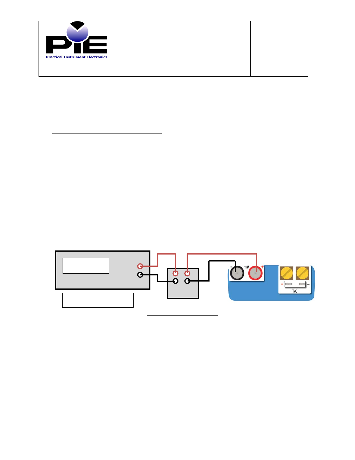
Note: There are two possible ways to calibrate the cold junction sensor.
1) Automatic Adjustment (recommended) of the UUC stores the actual cold junction
temperature as measured by the cold junction thermistor.
2) Manual Adjustment (optional) of the UUC stores a temperature that is manually entered
from readings of an external reference temperature device (RTD or thermistor) thermally
attached to the UUC.
Note: There is also an optional step to adjust the contrast of the LCD display. This is set at the
factory and should not require adjustment.
Automatic Cold Junction Temperature Reading:
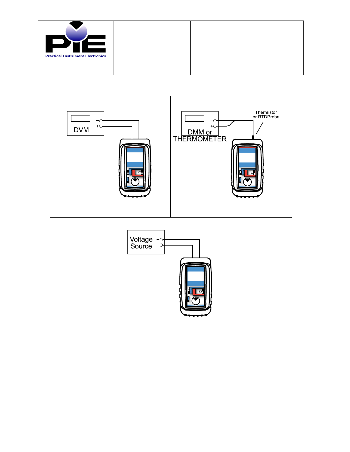
1) Leave all connections open
2) Move EZ-CHECK switch to SET. AUTOCAL TEMP should appear on the UUC LCD.
3) Press and hold the knob until the display shows STORE.
NOTE: This will reset Manual Temp calibration.
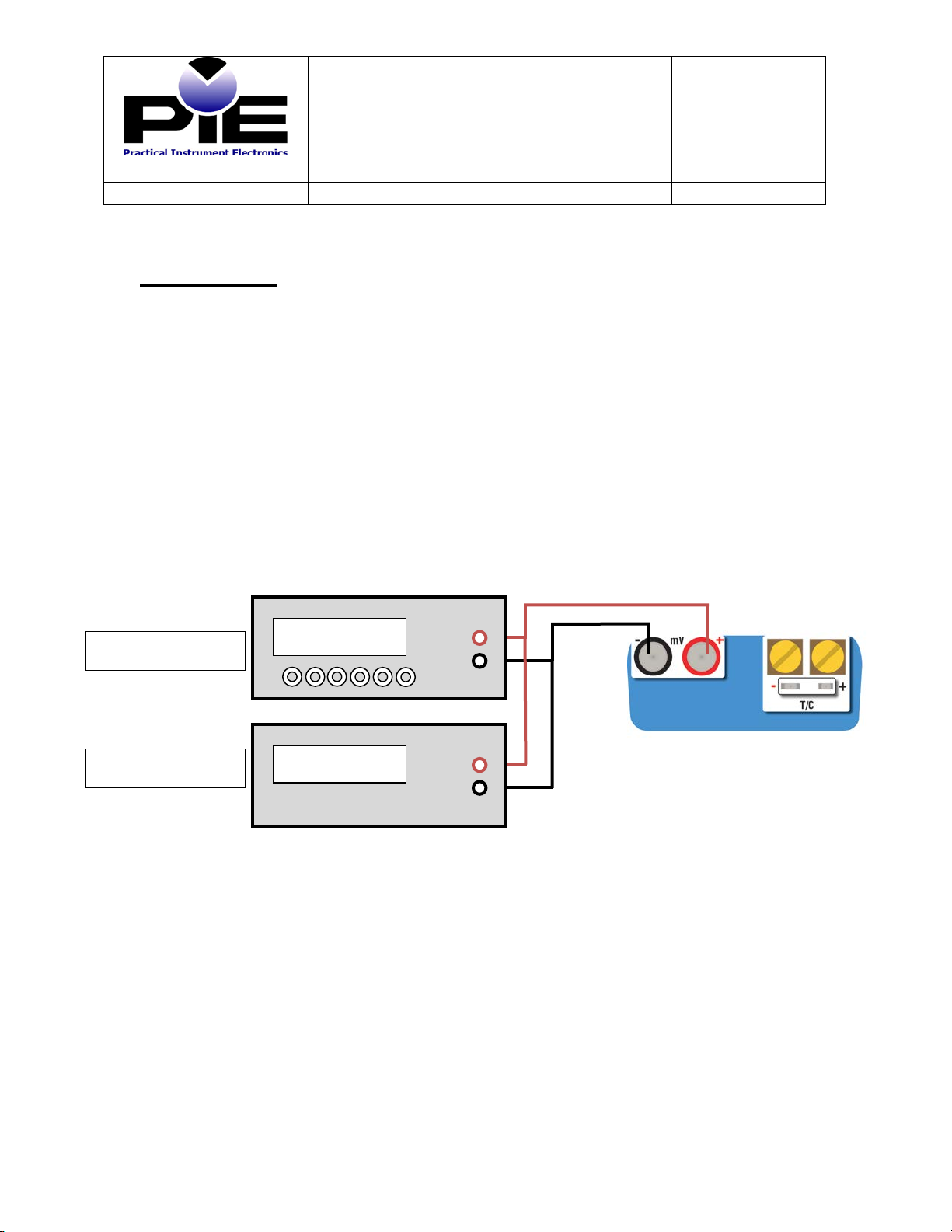
Manual Cold Junction Temperature Reading:
1) Leave all connections open
2) A user may perform a Manual Cold Junction Calibration however this will create an
offset from the calibrated Cold Junction Temperature and this may cause the unit to not
meet manufacturer’s specifications.
3) Remove one of the brass screws and place a small RTD or thermistor temperature probe
into the hole in the brass block. Alternatively place the temperature probe under the
screw and gently tighten the screw to hold the probe in place. Protect the temperature
probe from drafts.
4) Move EZ-CHECK switch to LO. MANUAL CAL TEMP should appear on the UUC
LCD. Important! Allow at least 15 minutes for the temperature to stabilize.
5) Dial the UUC to the Desired CJC temperature as measured by the temperature probe.
6) Press and hold the knob until the display shows STORE.
Contrast Adjustment:
1) Move EZ-CHECK switch to HI. CAL CONTRAST should appear on the UUC LCD.
2) Dial the UUC to the Desired LCD contrast
3) Press and hold the knob until the display shows STORE