LEM Analyst 3P User manual

Operating Instructions
Gebrauchsanleitung
Manuel d’utilisation
Power Quality Analyser
Analyst 3P
Test Equipment Depot - 800.517.8431 - 99 Washington Street Melrose, MA 02176
FAX 781.665.0780 - TestEquipmentDepot.com

2 Analyst 3P
EO 0620GDF Rev. E
Article number: EO 0620GDF
Version number: Revision E
Date: 08 / 2004
The manufacturer reserves the right to
change any information without notice.
© LEM HEME, All rights reserved

Contents
Analyst 3P 3
EO 0620GDF Rev. E
Table of Contents
1. General............................................................................................................... 5
1.1 Power Quality Analysis............................................................................5
1.2 Safety Instructions...................................................................................6
1.3 Standard and Optional Accessories........................................................9
1.4 Software and Information CD................................................................10
2. Putting your Analyser into Operation............................................................ 11
2.1 Accessories........................................................................................... 11
2.2 Carrying Belt .........................................................................................11
2.3 Control Elements, Display..................................................................... 12
2.4 Basic Adjustments (Menu) ....................................................................15
2.4.1 Menu Structuring...................................................................................15
2.4.2 Parameter Configuration.......................................................................18
3. Measuring Functions ...................................................................................... 21
3.1 Overview...............................................................................................21
3.2 Connecting the Analyser.......................................................................22
3.3 Volts / Amps / Hertz............................................................................... 24
3.4 Power....................................................................................................26
3.5 Events...................................................................................................29
3.6 Harmonics.............................................................................................31
3.7 Waveforms............................................................................................ 33
4. Analyst 3P Software........................................................................................ 34
4.1 Installing Analyst 3P Software............................................................... 34
4.2 Starting PQLog View.............................................................................34
4.3 Using PQLogView................................................................................. 35
4.4 Recording measurement data with ANALYST 3P................................. 36
5. Specific Data of the Analyser......................................................................... 39
5.1 Power Supply and Replacing the Battery Pack..................................... 39
5.2 Maintenance and Warranty ................................................................... 41
5.3 Calculation of the Measured Variables..................................................42
5.4 Technical Specification.......................................................................... 44

General
Analyst 3P 5
EO 0620GDF Rev. E
1.General
1.1 Power Quality Analysis
With this analyser you have acquired one of our high-quality, efficient and durable
multiple purpose test instruments. We thank you for your confidence.
By monitoring the voltage quality criteria, the final customer receives important
information about the quality of his power network as provided by the electricity
producer. With this Analyser you obtain the certainty that the power quality
corresponds to the EN50160 standard.
It is necessary to check the supply voltage regularly in order to ensure the perfect
functioning and working of the growing number of electronic devices. In connection
with the liberalisation of the energy market "Voltage Quality" is also becoming more
important for energy producers and final customers.
This device has been optimised for the fast identification of disturbances in the
power network.
With the help of the clear representation of all relevant parameters, it becomes
simple to detect systematic network problems.
Therefore the analyser was developed in particular for plant electricians and
electrical installers, who have an important role during the recovery of disturbances
of the power distribution system.
NOTE: FLASH TECHNOLOGY
Your Analyst 3P is equipped with Flash Technology. This enables you to perform
firmware updates. Please use the Windows Flash Update utility to do this. You will
find it on the Analyst CD-ROM.
Please find the most recent firmware - which is compatible to your instrument's
hardware - on the LEM Homepage.
http://www.lem.com
General
6 Analyst 3P
EO 0620GDF Rev. E
1.2 Safety Instructions
Please read this section carefully. It makes you familiar with the most
important safety instructions for handling your device.
Important
This power quality analyser may only be used and handled
by qualified personnel.
Protect the device against wetness and humidity, so that
the device does not suffer damage.
The plug and socket connection for the voltage input is
designed for 600V CAT III. The maximum voltage between
outer conductor and earth potential must not exceed 600V.
With multi-phase connections, the voltage between the outer
conductors of the system to be measured may not exceed
800V.
Warning
Current probes must comply to IEC 61010-2-032 category A
and must be designed for 600V CAT III. If flexible current
probes are used, the conductor to be enclosed by the probe
and the adjacent conductor must be connected strain-free,
or suitable protective gloves must be worn.
Warning
Open the device only to replace the accumulator package
(see chapter 4.1). Opening the device can lead to electrical
shocks. Therefore the device has to be separated from all
live sections before opening. Also disconnect all test leads
before using the RS232 interface. Maintenance work can
only be done by qualified service personnel.

General
Analyst 3P 7
EO 0620GDF Rev. E
Warning
When connecting current circuits, the corresponding
measuring lines must first be connected to the base unit and
then to the current sensor to prevent the risk of electric
shock in case of false connection.
Please use only the provided original accessories.
Especially the original power adapter must be used since it
is a safety-relevant component! Please use only the supplied
original adapter.

General
8 Analyst 3P
EO 0620GDF Rev. E
Symbols:
Qualified Personnel
These persons have the special know-how about the manufacturing,
assembly, connections and operation concerning these instruments.
Adequate qualifications are the following:
Having received training and authorization to switch on/off, earth and
mark circuits and devices in accordance with the safety standards of
electrical engineering.
Training or instruction in accordance with the standards of the safety
engineering in maintenance and use of appropriate safety
equipment.
Training in first aid.
Protective earth
Warning of danger (read
the documentation)
CE Certificate
Double insulation
according to IEC 61010-1;
Protective Class II;
600V CAT III
DC voltage

General
Analyst 3P 9
EO 0620GDF Rev. E
1.3 Standard and Optional Accessories
Contents of delivery Order number
ANALYSER Basic:
Basic unit 3-phase, voltage test leads 3-phase, 4 Dolphin
clips, NiMH-battery-package, mains adapter, protective
holster, carrying belt, RS232 interface
SH0620A
ANALYSER Set + LEM~flex set 3- phase + carrying case EP0621A
LEM~flex set 3-phase
15/150/3000A with 7 pin plug (delivered with
ANALYSER set only)
SX8315A
Voltage test leads 3-phase, 2 m E438080005
NiMH – battery package, 2700mAh / 7,2V (built-in) EP0610A
Transport and protection case (delivered with
ANALYSER set only) EP0611A
Operating instructions English, German and French EO 0620GDF
Operating instructions English, Spanish and Portuguese EO 0620ESP
Accessories and services
Description Order number
Voltage test leads 3-phase, 2 m E438080005
Voltage test leads 3-phase, 2 m, UK- colours E438080011
Voltage test leads 3-phase, 2 m long, USA-colours E438080018
Connector cable with Euro-plug for single phase
applications E438080015
LEM-flex 3 phase 15/150/3000A with 7 pin plug SX8315A
Set of current clamps 10A 3-phase SX8350A
Set of current clamps 50A / 5A 3-phase SX8450A
Set of current clamps 200A 3-phase SX8320A
Dolphin clamp, blue EP325Z
Dolphin clamp, red EP326Z
Dolphin clamp, black EP327Z
Minigripp, black, insulated EP0312Z
Certificate A3P - ASC 02 (LEM-certificate with list of
calibration points) for ANALYST 3P EP0620A

General
10 Analyst 3P
EO 0620GDF Rev. E
Description Order number
Power adapter (Euro) EP0612A
Adapter plug UK EUROCONV
Power adapter US EP0612U
Operating manual English, German and French EO0620GDF
Operating manual English, Spanish and Portuguese EO0620ESP
Carrying case EP0611A
Please pay attention upon delivery. Should your analyser have been
damaged during transport you have to call this to the attention of the
deliverer immediately. The damage must also be noted in the delivery
documents.
In case of damage, please send your device back to us but only with the
original packaging.
Please check all the accessories for completeness according to the
previous table.
1.4 Software and Information CD
The CD delivered with the Analyser contains additional, important
information. This includes:
•A demonstration of the download, analysis and reporting
software PQLogView.
•Information on upgrading your analyser (for future reference)
•Datasheets and manuals on LEM Portable Power Quality
Products
•A complete catalogue of LEM Instrument Products
Putting your Analyser into Operation
Analyst 3P 11
EO 0620GDF Rev. E
2. Putting your Analyser into Operation
Note:
The analyser is delivered with an empty battery pack. Please charge the
battery before the first operation or use the provided charging adapter at
the beginning. (for more Information see section “Power Supply and
Replacing the Battery Pack”).
2.1 Accessories
Optional accessories like LEM-Flex or current clamps will be detected by
the device via an auto-detection feature, which is activated once the device
is turned on.
It is important to turn the device on once accessories have been changed
to avoid possible discrepancies between the set accessories and the newly
connected accessories.
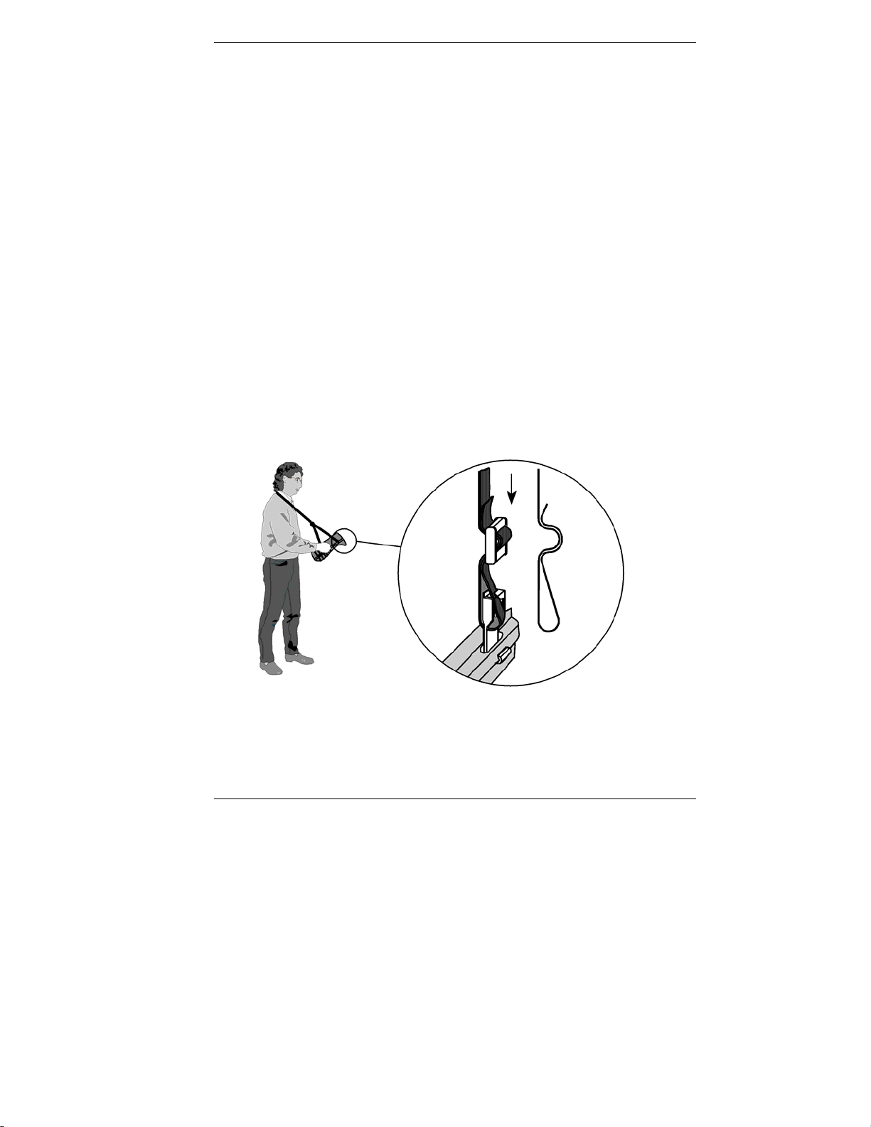
2.2 Carrying Belt
If you would like to use your analyser as a carry-on, you can use the
carrying belt. You can see in detail from the following figure, how you can
fasten it to the device and adapt the length.
Table of contents
Other LEM Test Equipment manuals


