PIE 850 User manual

Actual Size
Practical Instrument Electronics
82 E. Main Street Suite 3.14 • Webster, NY 14580 Tel: 585.872.9350 • Fax: 585.872.2638 • [email protected] • www.piecal.com
PIE 850
Process Calibrator
Get more tools
in a smaller calibrator
Carry eight single function calibrators
plus
a 4-20/10-50 milliamp calibrator with loop supply
plus
a loop troubleshooter in the palm of your hand!
Milliamp • Voltage • Frequency • pH
Ohms • Thermocouples • RTDs • Pressure
Loop Diagnostics • Transmitter Supply
10-50 mA Multifunction Calibrator
with troubleshooting tools
1
Detect ‘hidden’ loop problems
Quickly diagnose troublesome ground faults & current leakage
with patented Loop Diagnostic technology. These problems are
undetectable with other instruments!
2
Check all loop parameters at once with the LoopScope™
Simultaneously displays current, voltage and resistance to let
you know the condition of a live loop. Finds problems with power
supplies & loops with too many loads. Patented by PIE!
3
Troubleshoot wiring problems without a multimeter
Built in continuity checker with ‘beeper’ quickly finds broken wires
or shorts in instrumentation wiring. Also handy for checking
operation of relays and controller outputs.
The PIE Model 850 is more than a multifunction calibrator. It is also a loop
detective that is able to diagnose common problems that other test equipment just can’t find. Have a flooded junction
box or unknown ground faults? Our Loop Diagnostic technology will detect it. Or use the LoopScope to see at a
glance all the parameters - milliamps, voltage and resistance - in the loop.
Become a troubleshooting technician with Patented Diagnostic Technology - Available only with PIE Calibrators!

• Easy to use
With the 850 you can check, calibrate
and measure all of your current
signal instruments in 4 to 20 & 10 to
50 milliamp DC loops. It can be used
at any access point in your loop.
Milliamp Calibrator
• Source three ranges of mV & V dc
With the 850 you can check, calibrate
and measure all your voltage,
millivolt and pH signal instruments in
your plant. Source 0.000 to 10.250 V
dc, -500.00 to 999.99 mV and
-20.000 to 99.999 mV.
Voltage Calibrator
• Calibrate using loop power
Check loop wiring and receivers by using the 850 in
place of a 2 Wire transmitter. Uses any loop power from
2 to 60 V DC.
• Read loop current
Check controller outputs or measure the milliamp signal
anywhere in the loop. The 850 measures 0.000 to
52.000 mA (-25.00 to 125.00%) signals with greater
accuracy than a typical multimeter.
• Power & measure 2 wire transmitters
The 850 can simultaneously output 24V DC @ 20 mA
or 40V DC @ 50 mA to power any and all devices in a
process loop using the internal batteries and internal
switching power supply, while measuring the output of a
2 Wire Transmitter and any other loop devices. Powers
HART™ transmitters (4-20 mA only) with built-in 250
ohm resistor simplifying hookups with HART
communicators.
The 850 has an internal 40 V power supply which is able
to drive transmitters and positioners in 10-50 mA loops.
Some other brands of calibrators have a 24 V supply
which are unable to supply the power required to
properly drive these control devices.
• Read DC volts
The 850 can measure from 0.000 to 10.250 V, -999.99
to 999.99 mV, -99.999 to 99.999 mV and 0.00 to 60.0
VDC. Use it to check loop power supplies, I/V converters,
1 to 5 Volt signals, and other voltages.
Source & Read 0.000 to 24.000 or 52.000 mA, Simulate
a 2 Wire Transmitter or use the 850 to simultaneously
power your 2 Wire Transmitter and measure its output.
• Source milliamps
Calibrate recorders, digital indicators, stroke valves or
any instruments that get their input from a 4 to 20 or 10
to 50 mA loop. Easily set any value quickly to within
0.001 mA with the adjustable digital potentiometer
“EZ-DIAL” or use preset 4.000 or 10.000 mA (0.00%)
and 20.000 or 50.000 mA (100.00%) EZ-CHECK™
settings.
Easy to use Multifunction Calibrator
• Technician friendly operation
Intuitive EZ-DIAL Double Click Menu makes it easier to setup than other multifunction
calibrators. As easy to use as single function PIE Calibrators.
Turn on the backlight to
easily see the display in dark areas of the plant. Connections diagrams are indicated
on the display for each function along with a labeled connector and a help chart
behind the tilt stand.
• Calibrate with Confidence
Accurate to
±0.02% of Reading + 0.01% Full Scale.
• Measure temperature sensors, frequency pickups, loop currents, voltage levels & pressures
Check the values of your process sensors. Instantly recall MAX and MIN values to see process variability.
• Guaranteed Compatibility with process inputs
Compatible with the instruments you use including all brands of smart transmitters and PLCs with
14 T/C and 9 RTD
types to 0.1°C and 0.1°F
• Quickly set any three outputs plus automatic stepping & ramping
Easily set any value with the adjustable “DIAL” plus store any three output settings for instant recall with the EZ-CHECK™
switch. 2, 3, 5 & 11 steps automatically increment output in 100%, 50%, 25% or 10% of span plus continuous ramp. Set
step/ramp time to 5, 6, 7, 8, 10, 15, 20, 25, 30 & 60 seconds.
Connections

• Calibrate ALL your RTD instruments
RTD, Resistance Calibrator
• Simulate pH probes into transmitters & analyzers
Use the pH simulator to verify proper operation of pH
devices before you place a probe into a calibrated buffer.
Adjusting the pH transmitter or analyzer without a probe
allows you to make sure the device is calibrated and
doesn’t require too much offset with the probe. If the
probe requires more than the manufacturer’s
pH Simulator
• Calibrate flow meters and frequency instruments
Frequency Calibrator
• Checkout optical pickups
The 850 has a green LED that flashes in sync with the
output frequency. Select a frequency and hold the
calibrator up to the optical sensor.
• Measure frequency signals
Check the values of your process frequency outputs.
Instantly recall MAX and MIN values to see process
variability.
• Compatible with ALL process instruments
No competitor’s calibrator is compatible with as many
process instruments! Connect directly to the RTD inputs
of smart transmitters, PLCs, DCS and multichannel
recorders and verify their outputs or displays. Works with
older instruments with fixed excitation currents and
newer multichannel instruments that switch the excitation
current between input channels.
• Measure RTD sensors
Connect your two, three or four wire RTDs and the 850
measures the RTD within 0.1 degree C or F. Check the
values of your process sensors. Instantly recall MAX
and MIN values to see process variability.
Generate zero crossing square
waves to check, calibrate and
measure all the frequency signal
instruments in your plant. Source
and read frequencies from 1 to 2000
CPM (Counts-Per-Minute), 0.01 to
999.00 Hz, 0.1 to 9999.9 Hz and
0.001 to 20.000 kHz.
With the 850 you can check &
calibrate all your RTD instruments
and measure RTD Sensors.
• Calibrate directly in temperature (°C & °F)
Stop carrying around a decade box and RTD resistance
tables. The 850 works with the RTDs you use including
Platinum 100 (alpha = 3850, 3902, 3916, 3926) & 1000
(alpha = 3850) Ohm, Copper 10 & 50 Ohm, Nickel 100
and 120 Ohm. Easily set any value quickly to within 0.1°
with the adjustable digital potentiometer “EZ-DIAL” plus
store any three temperatures for instant recall with the
EZ-CHECK™ switch. Or use like a decade box from
0.00 to 401.00 and from 0.0 to 4010.0 Ohms.
• Troubleshoot wiring and connection problems
Use the built-in continuity checker to look at wiring and
connections during installation or to locate shorts.
Beeps from 0 to 100 Ohms.
Continuity Checker
recommendations (typically 5%) it is time to replace the
probe. The 850 simulates 0.000 to 14.000 pH @ 25°C
corresponding to +414.12 to -414.12 mV.
Thermocouple Calibrator
• Calibrate directly in temperature to 0.1°C & 0.1°F • Measure thermocouple sensors
Trouble shoot sensor connections and find broken wires
or corroded connections. Connect your thermocouple
with a miniature thermocouple connector and the 850
measures the probe to 0.1 degree C or F. Check the
values of your process sensors. Instantly recall MAX and
MIN values to see process variability.
Stop carrying around a millivolt source
and thermocouple tables. The 850
works with the thermocouples you
use including types J, K, T, E, R, S, B,
N, G, C, D, L (J-DIN), U (T-DIN) and P
(Platinel II). Easily set any value
quickly to within 0.1° with the
adjustable digital potentiometer
“EZ-DIAL” plus recall any three
temperatures for instant recall with
the EZ-CHECK™ switch.

Typical problem found with Leak Detection
Have you ever replaced a “faulty” transmitter only to find the problem was somewhere else in the loop? And did you end up
throwing the transmitter away after you fixed the other problem “just in case” the transmitter was faulty?
If you find a loop where the transmitter is calibrated correctly but all the readings elsewhere in the loop have a fixed offset this is
due to a Zero Shift. This zero shift is typically caused by some current in the loop bypassing the transmitter. This might be caused
by ground faults, moisture or corrosion.
If you have some loops that are erratic after it rains there may be moisture present in a junction box or where insulation has
broken down. Turn on Ground Leak Detection and use the PIE 850 to power up the loop. Any current that isn’t controlled by the
transmitter or other current control element will be indicated as leakage on the PIE 850 display. Undetected current leaks may cause
calibration errors which can lead to dangerous operating conditions or catastrophic results.
The PIE 850 powers up the 2-Wire transmitter or loop and indicates the total current and the uncontrolled current. This provides
information useful in troubleshooting loop errors.
Troubleshoot Loop Problems
Automatic indication of Loop Current
and Leakage Current (US Patent
#7,248,058) in both 4-20 and 10-50
mA loops. Measure ground current
leakage from faulty wiring, flooded
conduit and corrosion bridges to
help you decide if there is a wiring
problem in the loop (diagrams below).
• Find current leaks in loops before swapping instruments
T
Flooded
junction
box or
corroded
terminals
AUTOMATED DIAGNOSTICCALIBRATOR
ransmitter
input signal at
50% of Span Transmitter
regulating
current to
12.00 mA
SOURCE
HI
SET
LO
OFF
MAX
READ
MIN
READ
OVERLOAD
HzSYNC
Double Click
Menu
Push& Turn
for
FastDialing
Push& Hold
to
Store/Step
mA ∙ V ∙ pH ∙ TC ∙ Ω ∙ RTD ∙ Freq ∙ Pressure
PWRM LEAK
HART
12.414mA
12.414 mA
PWRM LEAK
00.45 mA
HART
00.45 mA
12.41mA
Control
System
Transmitter
regulating
current to
12.00 mA
Transmitter
input signal at
50% of Span
Junction
Box
Here is a loop where a technician has just recalibrated
the transmitter but the control room still sees a problem.
The problem started just after a rainstorm.
Using the PIE 850 to power up the loop the technician detects
a leakage of 0.45 mA - approximately the offset seen in the
control room. He walks the loop and opens a junction box
releasing a stream of water. The loop is again in control.
850 detects uncontrolled
current in the loop due
to a flooded junction
box.

• Designed for you by experienced calibrator manufacturers
PIE Calibrators are designed and built by members of the same team that designed and built the calibrators
manufactured by Fluke* under the Altek* label. The 850 improves upon other brands by including a rubber boot, backlit
display with larger digits, troubleshooting tools, higher accuracy and more ranges for flexibility.
Evolutionary Design
* PIE Calibrators are not manufactured or distributed by Fluke Corp or Altek Industries Inc, manufacturers of Altek Calibrators.
Become a Loop Detective - Locate hidden loop problems with LoopScope
When you need to find out why a loop is out of control and all the wiring seems to be in order turn on the 850’s LoopScope and
simultaneously see all the parameters of the loop. The LoopScope simultaneously displays the current, DC voltage and total
resistance in the loop. Observing the SUPPLY (DC voltage) and the LOAD (resistance) lets you see if the loop power supply has
enough capacity to power all the devices in the loop.
By observing all three signals at the same time you can see how the voltage and resistance respond as the current changes. If
the voltage drops too far as the current goes up you may need a power supply with more capacity or the power supply itself may
be failing. If the resistance in the loop is too high you may have more devices in the loop than the power supply can handle or there
may be an instrument in the loop that is drawing too much power and requires replacement.
Why buy a PIE calibrator with loop diagnostics
Undiagnosed loop problems often cause calibration errors which can
lead to dangerous operating conditions or catastrophic results. Only PIE
makes troubleshooting multifunction calibrators that can detect and
indicate these problems due to the patented troubleshooting features.
With LoopScope running the
850 simultaneously controls
and displays the loop current
while measuring & displaying
the power supply voltage and
loop load in ohms.

Accessories
Optional
Three Year Repair/Replacement Warranty........................................................... RP-WAR-B
Evolution Hands Free Carrying Case with Pressure Module Pocket............... 020-0223
Optional Hand Pumps, Tubing & Fitting Kits
AP0V 0-300 PSI/20.7 bar Pneumatic Scissor Hand Pump ................................. 020-0224
HP0V 0-3000 PSI/206.9 bar Hydraulic Scissor Hand Pump............................... 020-0225
DPPV 0-125 PSI/8.6 bar Pressure, 23”/584 mm Hg Vacuum hand pump ......... 020-0226
1/8” male NPT x Male Quick-Test™ Fitting with Cap........................................... 020-0227
Adapter kit (1/8” MNPT&FNPT; 1/4” MNPT, FNPT & Tube Adapter)................... 020-0228
Quick-Test™ 6900 psi/475 bar hose, 3ft (1 m)................................................... 020-0229
PKIT1 (020-0224 Pneu Scissor Pump, 020-0229 Hose & 020-0227 fitting)...... 020-0230
PKIT2 (020-0225 Hydr Scissor Pump, 020-0229 Hose & 020-0227 fitting) ...... 020-0231
PKIT3 (020-0226 Press/Vac Pump, 020-0229 Hose & 020-0227 fitting)........... 020-0232
Optional Pressure Modules
0-10“/24.9 mbar H20 Differential, Non Isolated.................................................. DN0010
0-28“/69.7 mbar H20 Differential, Non Isolated.................................................. DN0028
0-200“/498 mbar H20 Differential, Non Isolated................................................. DN0200
0-415“/1 bar H20 Differential, Non Isolated........................................................ DN0415
0-2000“/5 bar H20 Differential, Non Isolated...................................................... DN2000
0-1 PSI/68.9 mbar Differential, Isolated.............................................................. DI0001
0-5 PSI/344.7 mbar Differential, Isolated............................................................ DI0005
0-15 PSI/1 bar Differential, Isolated.................................................................... DI0015
0-30 PSI/2 bar Differential, Isolated.................................................................... DI0030
0-100 PSI/6.9 bar Differential, Isolated............................................................... DI0100
0-300 PSI/20.7 bar Differential, Isolated............................................................. DI0300
0-500 PSI/34.5 bar Differential, Isolated............................................................. DI0500
0 to 15 PSI/1 bar Gauge, Isolated....................................................................... GI0015
0 to 30 PSI/2 bar Gauge, Isolated....................................................................... GI0030
0 to 50 PSI/3.4 bar Gauge, Isolated.................................................................... GI0050
0 to 100 PSI/6.9 bar Gauge, Isolated.................................................................. GI0100
0 to 300 PSI/20.7 bar Gauge, Isolated................................................................ GI0300
0 to 500 PSI/34.5 bar Gauge, Isolated................................................................ GI0500
0 to 1,000 PSI/69 bar Gauge, Isolated................................................................ GI1000
0 to 3,000 PSI/206.8 bar Gauge, Isolated........................................................... GI3000
-14.7 PSIG/1 bar to +15 PSIG/1 bar Compound, Isolated .................................. CI0015
-14.7 PSIG/1 bar to +30 PSIG/2 bar Compound, Isolated .................................. CI0030
-14.7 PSIG/1 bar to +50 PSIG/3.4 bar Compound, Isolated ............................... CI0050
-14.7 PSIG/1 bar to +100 PSIG/6.9 bar Compound, Isolated ............................. CI0100
-14.7 PSIG/1 bar to +300 PSIG/20.7 bar Compound, Isolated ........................... CI0300
-14.7 PSIG/1 bar to +500 PSIG/34.5 bar Compound, Isolated ........................... CI0500
-14.7 PSIG/1 bar to +1,000 PSIG/69 bar Compound, Isolated ........................... CI1000
-14.7 PSIG/1 bar to +3,000 PSIG/ 206.8 bar Compound, Isolated ..................... CI3000
0-17 PSIA/1.2 bar Absolute, Isolated.................................................................. AI0017
0-38 PSIA/2.6 bar Absolute, Isolated.................................................................. AI0038
0-100 PSIA/6.9 bar Absolute, Isolated................................................................ AI0100
0-1,000 PSIA/69 bar Absolute, Isolated.............................................................. AI1000
Ordering Information
Description Part No
PIE Model 850 Process Calibrator ............................................................. PIE Model 850
Included:
Four “AA” Lithium Ion batteries, Certificate of Calibration with Test Data
Blue Rubber Boot ............................................................................................... 020-0213
Evolution Hands Free Carrying Case ................................................................... 020-0211
Evolution mA/V Test Leads ................................................................................. 020-0207
1 Red & 1 Black Lead
with Banana Plugs & Alligator Clips
Evolution RTD Wire Kit ....................................................................................... 020-0208
2 Red & 2 Black Leads with Banana Plugs & Spade Lugs
Pressure Module Media Compatibility
Non-isolated DN sensors: clean, dry,
non-corrosive, non-condensing gases only
Isolated DI sensors: any media
compatible with 316L SS & Viton®
Isolated GI, CI & AI sensors: any media
compatible with 316L SS

Measure Pressure
Purchase any of the pressure modules from the table below along with one of the three hand pumps and tubing kits
for a complete pressure calibration system.
Sensor Code Application Ranges Available
DNxxxx Differential, Non-isolated 0 to 0010*, 0028, 0200, 0415, 2000” H2O
DIxxxx Differential, Isolated 0 to 0001, 0005, 0015, 0030, 0100, 0300, 0500 PSID
GIxxxx Gauge, Isolated 0 to 0015, 0030, 0050, 0100, 0300, 0500, 1000, 3000 PSIG
CIxxxx Compound, Isolated -14.7 to +0015, 0030, 0050, 0100, 0300, 0500, 1000, 3000 PSIG
AIxxxx Absolute, Isolated 0 to 0017, 0038, 0100, 1000 PSIA
Media Compatibility
Non-isolated DN sensors: clean, dry, non-corrosive, non-condensing gases only
Isolated DI sensors: any media compatible with 316L SS & Viton®
Isolated GI, CI & AI sensors: any media compatible with 316L SS
Accuracy
±0.025% of full scale including all effects of linearity, repeatability and hysteresis from -20° to +50°C (-4° to +122°F)
* The DN0010 sensor accuracy is ±0.050% of full scale
32 Engineering Units:
PSI • inches, feet, mm, cm and meter of H2O @ 4°C, 20°C & 60°F • inches, meter, cm and mm of Hg @ 0°C;
torr • kg/cm2 • kg/m2 • Pa • hPa • kPa • MPa • Bar • mBar • ATM • oz/in2 • lb/ft2
• Easily measure pressure with a plug in pressure module
PIE 850 with Pressure Module, Pressure/Vacuum Pump & Hose

Pneumatic Scissor Hand Pump
0 to 300 psi
Pneumatic Pressure/Vacuum Pump
0 to 125 psi & 0 to 23 inches vacuum
Hydraulic Scissor Hand Pump
0 to 3,000 psi
Pressure Fitting Kit
Adapts from Quick-test™ hose to 1/4” male & female
NPT, 1/8” male & female NPT and 1/4” tube fitting
Quick-test™ Hoses
Microbore hoses provide a very quick, low volume, high
pressure way of connecting any pressure
instrumentation to the hand pump and pressure module.
Hand Pumps,Tubing & Fitting Kits
• Generate pressure with a full set of hand pumps
Choose from a selection hand pumps, tubing & fittings made in the USA by Ralston Instruments. All pumps have two
pressure ports - one port & hose go the PIE pressure module and the other to the pressure input of your instrument.

Hands free carrying case with pockets for the PIE 850 and the Pressure Module.
Back of case has zipped pocket for the manual, test leads, hoses & pressure fittings.
Hands free carrying case with
pockets for the PIE 850 and the
Pressure Module.
Designed to be worn around
your neck so that you can safely
use both hands to calibrate.

PIE 850 Specifications
(Unless otherwise indicated all specifications are rated from a nominal 23°C, 70% RH for 1 year from calibration)
General
Operating Temperature
Range
-20 to 60 °C (-5 to 140 °F)
Storage Temperature Range -30 to 60 °C (-22 to 140 °F)
Temperature effect ≤ ± 0.005 %/°C of Full Scale; Cold Junction Sensor
≤ ±25 ppm/°C
Relative Humidity Range 10 % ≤RH ≤90 % (0 to 35 °C), Non-condensing
10 % ≤RH≤ 70 % (35 to 60 °C), Non-condensing
Common Mode Rejection 50/60 Hz, 100 dB
Normal Mode Rejection 50/60 Hz, 50 dB
Noise ≤ ± ½ Least Significant Digit from 0.1 to 10 Hz
Size 5.63 x 3.00 x 1.60 in, 143 x 76 x 41mm (L x W x H)
Weight 12.1 ounces, 0.34 kg (including boot & batteries)
Batteries Four “AA” Lithium 1.5V (LR6)
Battery Life
Read Functions ≥ 20 hours; Read Pressure ≥ 7 hours
Source mA: ≥ 14 hours @ 12 mA into 250Ω
≥ 9.5 hours @ 30 mA into 250Ω
Pwr/Meas: ≥ 12 hours @ 20 mA, ≥ 4.5 hours @ 50 mA
Source V, Ω, T/C, pH, RTD & Hz ≥ 20 hours
Low Battery Low battery indication with nominal 1 hour of
operation left
Protection against
misconnection
Over-voltage protection to 60 vrms (rated for 30
seconds). Red LED indicates OVERLOAD or out of
range conditions
Display High contrast graphic liquid crystal display with
0.35” (9 mm) high digits on main & 0.2” (5 mm) on
mA display. LED backlighting for use in low lit areas.
Read mA
Ranges and Resolution
0.000 to 24.000 mA or -25.00 to 125.00% of 4-20 mA
0.000 to 52.000 mA or -25.00 to 105.00% of 10-50 mA
Accuracy ≤ ± (0.02 % of Reading + 0.003 mA)
Voltage burden ≤ 2V at 24 mA. ≤ 2 V at 52 mA.
Overload/Current limit
protection
25 mA nominal in 20 mA range
52.5 mA nominal in 50 mA range
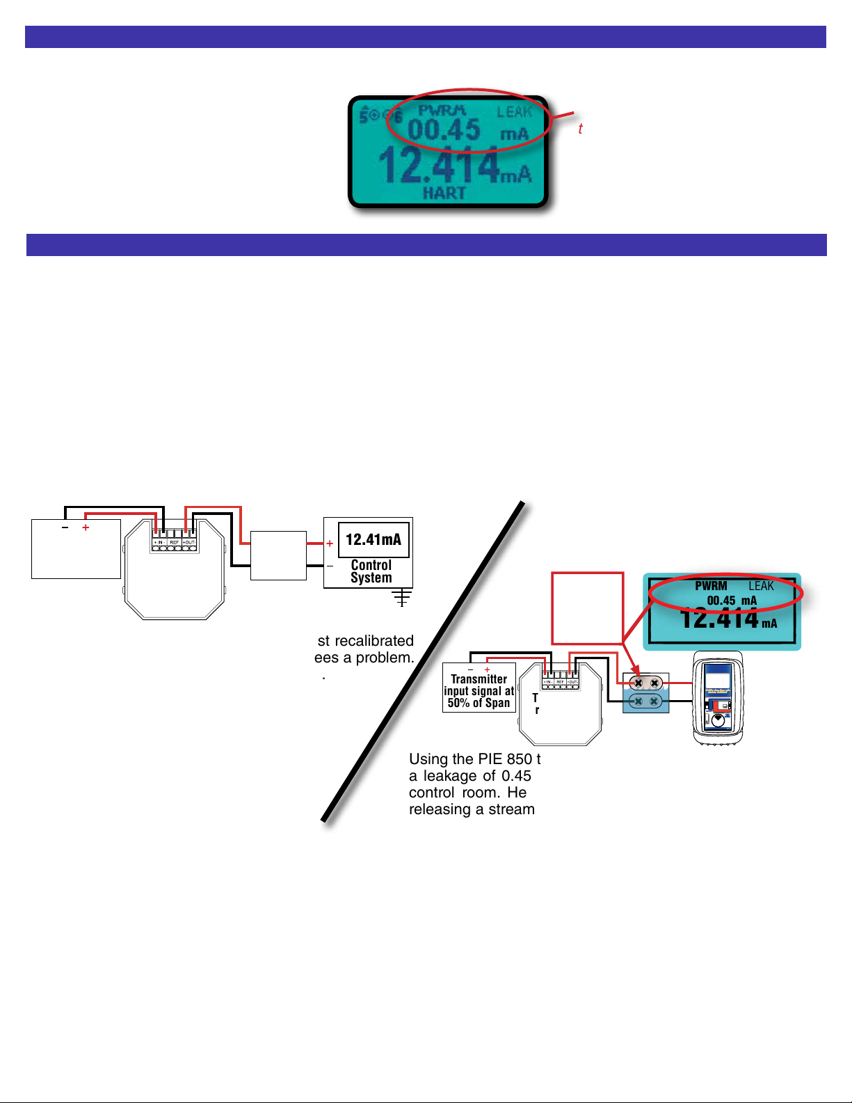
Source mA / Power & Measure Two Wire Transmitters & PWRM LEAK
Ranges and Resolution
0.000 to 24.000 mA or -25.00 to 125.00% of 4-20 mA
0.000 to 52.000 mA or -25.00 to 105.00% of 10-50 mA
Accuracy ≤ ± (0.02 % of Reading + 0.003 mA)
Loop compliance voltage
≥ 24 DCV @ 20.00mA. ≥ 2 DCV @ 50.000mA
Loop drive capability 1200 Ω at 20 mA for 15 hours nominal; 800 Ω at
50 mA for 4.5 hours nominal
Subtract 250Ω with Hart Resistor enabled (4-20 Only)
mA 2-Wire Transmitter Simulation
Accuracy Same as Source/Power & Measure
Voltage burden ≤ 2V at 24 mA. ≤ 2 V at 52 mA.
Overload/Current limit
protection
25 mA nominal in 20 mA range
52.5 mA nominal in 50 mA range
Loop voltage limits 2 to 60 VDC (fuse-less protected from reverse
polarity connections)
Source V dc
Ranges and Resolution
-20.000 to 99.999 mV, -500.00 to 999.99 mV, 0.000 to 10.250V
Accuracy ≤ ± (0.02 % of Reading + 0.01% Full Scale)
Source Current
≥ 20 mA
Sink Current > 16 mA
Output Impedance < 1 Ohm
Short Circuit Duration Infinite
Thermocouple Source
Accuracy ≤ ± (0.02 % of Reading + 0.01 mV)
Cold Junction Compensation
± 0.05°C - Thermistor traceable to NIST for 11 years
Output Impedance < 1 Ohm
Source Current > 20 mA (drives 80 mV into 10 Ohms)
Thermocouple Read
Accuracy & Cold
Junction Compensation
Same as Thermocouple Source
Input Impedance
> 1 Megohms
Open TC Threshold; Pulse
10K Ohms; <5 µamp pulse for 300 milliseconds (nominal)
RTD, OHMS and Continuity Read
Resistance Ranges 0.00 to 401.00, 0.0 to 4010.0 Ohms
Accuracy ±(0.025% of Reading + 0.075 Ohms)
Excitation Current
1.0 mA to 401 Ohms, 0.5 mA to 4010 Ohms (nominal)
Continuity 0.0 to 401.0 Ohms; Beeps from 0.0 to 100.0 Ohms
RTD and OHMS Source
3 Wire & 4 Wire Accuracy
F r o m 1 t o 1 0 . 2 m A
External Excitation Current
B e l o w 1 m A o f E x t e r n a l
Excitation Current
2 Wire Accuracy
±(0.025% of Reading + 0.075 Ohms)
±(0.025% of Reading+0.075 Ohms
+ )
Add 0.1 Ohms to 3 Wire & 4 Wire Accuracy
Resistance Ranges 0.00 to 401.00, 0.0 to 4010.0 Ohms
Allowable Excitation
Current Range
<401 Ohm:10.2 mA max; steady or pulsed/intermittent
401 to 4000 Ohms: 1 mA max; steady or pulsed/intermittent
Pulsed Excitation
Current Compatibility
DC to 0.01 second pulse width
0.025 mV
mA Excitation Current
Frequency Source
Ranges 1 to 2000 CPM, 0.01 to 999.99 Hz, 0.1 to 9999.9 Hz,
0.001 to 20.000 kHz
Accuracy ±(0.02% of Reading + 0.01% of Full Scale)
Output Waveform
Square Wave, Zero Crossing -1.0 to +5 V peak-to-peak ±10%
Risetime (10 to 90% of
amplitude)
< 10 microseconds
Output Impedance < 1 Ohm
Source Current > 1 mA rms at 20 kHz
Short Circuit Duration Infinite
Optical Coupling Green LED (HZ SYNC) flashes at output frequency
Frequency Read
Ranges & Accuracy Same as Frequency Source
Accuracy ±(0.02% of Reading + 0.01% of Full Scale)
Trigger Level 1 V rms, dc coupled
Input Impedance > 1 Meg Ohm + 60 pF
Specifications subject to change without notice.
pH Source
Accuracy in mV
Accuracy in pH
≤ ± (0.02 % of Reading in mV + 0.1 mV)
≤ ± 0.003 pH @ 25°C
Voltage Read
Range and Resolution
±99.999 mV, ±999.99mV, 0 to 10.250 V, 0.00 to 60.00 V DC
Accuracy ≤ ± (0.02 % of Reading + 0.01% Full Scale)
Input resistance ≥ 1 MΩ

RTD
Type
Alpha Degrees C
Range
°C
Degrees F
Range
°F
Pt 100 Ohm
DIN/IEC/JIS 1989
Based on ITS-90
1.3850
(0.00385)
-200.0 to 0.0
0.0 to 340.0
340.0 to 640.0
640.0 to 850.0
±0.2°
±0.3°
±0.4°
±0.5°
-328.0 to 32.0
248.0 to 644.0
644.0 to 1184.0
1184.0 to 1562.0
±0.4°
±0.6°
±0.8°
±1.0°
Pt 100 Ohm
(Burns)
1.3902
(0.003902)
-200.0 to 10.0
10.0 to 350.0
350.0 to 650.0
650.0 to 850.0
±0.2°
±0.3°
±0.4°
±0.5°
-328.0 to 50.0
50.0 to 662.0
662.0 to 1202.0
1202.0 to 1562.0
±0.4°
±0.6°
±0.8°
±0.9°
Pt 100 Ohm
(Old JIS 1981)
1.3916
(0.003916)
-200.0 to 20.0
20.0 to 360.0
360.0 to 650.0
650.0 to 850.0
±0.2°
±0.3°
±0.4°
±0.5°
-328.0 to 68.0
68.0 to 680.0
680.0 to 1202.0
1202.0 to 1562.0
±0.4°
±0.6°
±0.8°
±0.9°
Pt 100 Ohm
(US Lab)
1.3926
(0.003926)
-200.0 to 20.0
20.0 to 360.0
360.0 to 660.0
660.0 to 850.0
±0.2°
±0.3°
±0.4°
±0.5°
-328.0 to 68.0
68.0 to 680.0
680.0 to 1220.0
1220.0 to 1562.0
±0.4°
±0.6°
±0.8°
±0.9°
RTD Ranges & Accuracies
Thermocouple Ranges & Accuracies @ 23°C
RTD
Type
Alpha Degrees C
Range
°C
Degrees F
Range
°F
Pt 1000 Ohm
DIN/IEC/JIS 1989
1.3850
(0.00385)
-200.0 to 0.0
0.0 to 340.0
340.0 to 640.0
640.0 to 850.0
±0.2°
±0.3°
±0.4°
±0.5°
-328.0 to 32.0
248.0 to 644.0
644.0 to 1184.0
1184.0 to 1562.0
±0.4°
±0.6°
±0.8°
±1.0°
Copper 10 Ohm
(Minco)
1.4274
(0.004274)
-200.0 to 260.0
±2.0°
-328.0 to 500.0
±3.6°
Copper 50 Ohm
1.4280
(0.00428)
-50.0 to 150.0
±0.4°
-58.0 to 302.0
±0.8°
Ni 120 Ohm
(Pure)
1.6720
(0.00672)
-80.0 to 260.0
±0.1°
-112.0 to 500.0
±0.3°
Ni 110
(Bristol 7 NA)
1.5801
(0.005801)
-100.0 to 260.0
±0.2°
-148.0 to 500.0
±0.4°
T/C Degrees C
Range
°C Degrees F
Range
°F T/C
Material
J-200.0 to -50.0 ±0.5° -328.0 to -58.0 ±1.0° +Iron
-Connstantan
-50.0 to 300.0 ±0.2° -58.0 to 572.0 ±0.4°
300.0 to 900.0 ±0.3° 572.0 to 1652.0 ±0.6°
900.0 to 1200.0 ±0.4° 1652.0 to 2192.0 ±0.8°
K-230.0 to -50.0 ±1.2° -382.0 to -58.0 ±2.2° + Chromel®
-Alumel®
-50.0 to 550.0 ±0.3° -58.0 to 1022.0 ±0.6°
550.0 to 1000.0 ±0.5° 1022.0 to 1832.0 ±0.8°
1000.0 to 1371.1 ±0.6° 1832.0 to 2500.0 ±1.1°
T-260.0 to -230.0 ±2.9° -436.0 to -382.0 ±5.2° +Copper
-Constantan
-230.0 to -210.0 ±1.0° -382.0 to -346.0 ±1.9°
-210.0 to -50.0 ±0.8° -346.0 to -58.0 ±1.4°
-58.0 to 50.0 ±0.3° -58.0 to 122.0 ±0.6°
50.0 to 400.0 ±0.2° 122.0 to 752.0 ±0.4°
E-240.0 to -200.0 ±0.9° -400.0 to -328.0 ±1.7° +Chromel
-Constantan
-200.0 to 0.0 ±0.5° -328.0 to 32.0 ±0.8°
0.0 to 350.0 ±0.2° 32.0 to 662.0 ±0.3°
350.0 to 1000.0 ±0.3° 662.0 to 1832.0 ±0.6°
R-18.3 to 100.0 ±2.1° -1.0 to 212.0 ±3.8° +Pt/13Rh
-Platinum
100.0 to 500.0 ±1.3° 212.0 to 932.0 ±2.4°
500.0 to 1400.0 ±1.0° 932.0 to 2552.0 ±1.8°
1400.0 to 1767.8 ±1.2° 2552.0 to 3214.0 ±2.0°
S-18.3 to 100.0 ±2.0° -1.0 to 212.0 ±3.7° +Pt/10Rh
-Platinum
100.0 to 350.0 ±1.4° 212.0 to 662.0 ±2.5°
350.0 to 1600.0 ±1.1° 662.0 to 2912.0 ±2.0°
1600.0 to 1767.8 ±1.3° 2912.0 to 3214.0 ±2.4°
B315.6 to 600.0 ±3.2° 600.0 to 1122.0 ±5.7° +Pt/30Rh
-Pt/6Rh
600.0 to 850.0 ±1.7° 1122.0 to 1562.0 ±3.1°
850.0 to 1100.0 ±1.3° 1562.0 to 2012.0 ±2.4°
1100.0 to 1820.0 ±1.1° 2012.0 to 3308.0 ±2.0°
T/C Degrees C
Range
°C Degrees F
Range
°F T/C
Material
N-230.0 to -150.0 ±1.9° -382.0 to -238.0 ±3.4° +Nicrosil
-Nisil
-150.0 to -50.0 ±0.7° -238.0 to -58.0 ±1.2°
-50.0 to 950.0 ±0.4° -58.0 to 1742.0 ±0.8°
950.0 to 1300.0 ±0.5° 1742.0 to 2372.0 ±1.0°
G
(W)
100.0 to 350.0 ±1.7° 212.0 to 662.0 ±3.0° +Tungsten
-W26/Re
350.0 to 1700.0 ±0.8° 662.0 to 3092.0 ±1.5°
1700.0 to 2000.0 ±1.0° 3092.0 to 3632.0 ±1.8°
2000.0 to 2320.0 ±1.1° 3632.0 to 4208.0 ±2.1°
C
(W5)
-1.1 to 100.0 ±0.8° 30.1 to 212.0 ±1.4° +W5/Re
-W26/Re
100.0 to 1000.0 ±0.7° 212.0 to 1832.0 ±1.3°
1000.0 to 1750.0 ±1.2° 1832.0 to 3182.0 ±2.1°
1750.0 to 2320.0 ±2.0° 3182.0 to 4208.0 ±3.5°
D-1.1 to 150.0 ±1.0° 30.1 to 302.0 ±1.8° +W3/Re
-W25/Re
150.0 to 1100.0 ±0.7° 302.0 to 2012.0 ±1.3°
1100.0 to 1750.0 ±1.0° 2012.0 to 3182.0 ±1.8°
1750.0 to 2320.0 ±2.0° 3182.0 to 4208.0 ±3.6°
P0.0 to 600.0 ±0.3° 32.0 to 1112.0 ±0.6°
+Pd55/Pt31/
Au14
-Au65/Pd35
600.0 to 900.0 ±0.4° 1112.0 to 1652.0 ±0.8°
900.0 to 1200.0 ±0.6° 1652.0 to 2192.0 ±1.1°
1200.0 to 1395.0 ±0.7° 2192.0 to 2543.0 ±1.2°
L
J-DIN
-200.0 to -50.0 ±0.4° -328.0 to -58.0 ±0.7° +Iron
-Connstantan
-50.0 to 300.0 ±0.2° -58.0 to 572.0 ±0.4°
300.0 to 900.0 ±0.3° 572.0 to 1652.0 ±0.5°
U
T-DIN
-200.0 to -50.0 ±0.6° -328.0 to -58.0 ±1.1° +Copper
-Constantan
-50.0 to 50.0 ±0.3° -58.0 to 122.0 ±0.5°
50.0 to 550.0 ±0.2° 122.0 to 1022.0 ±0.4°
550.0 to 600.0 ±0.3° 1022.0 to 1112.0 ±0.5°
Table based on Thermocouple Accuracy ≤ ± (0.02 % of Reading in mV +0.01 mV)
Note: Doesn’t include cold junction error of ±0.05°C
Table based on 3 & 4 Wire RTD Accuracy: ≤ ± (0.025 % of Reading +0.075 Ohms)

Standard Warranty
Our equipment is warranted against defective material and
workmanship (excluding batteries) for a period of three years
from the date of shipment. Claims under warranty can be made
by returning the equipment prepaid to our factory.The equipment
will be repaired, replaced or adjusted at our option. The liability
of Practical Instrument Electronics (PIE) is restricted to that
given under our warranty. No responsibility is accepted for
damage, loss or other expense incurred through sale or use of
our equipment. Under no condition shall Practical Instrument
Electronics, Inc. be liable for any special, incidental or
consequential damage.
Pressure sensors that have been damaged by over
pressurization or contaminated by process chemicals are not
covered by our warranty.Pneumatic pumps that are contaminated
with process chemicals are also not covered by our warranty.
Optional Repair/Replacement Warranty
Under our Repair/Replacement Warranty (RP-WAR-B), our
equipment is warranted against ANY damage or malfunction
that may cause the unit to fail for a period of three (3) years from
the date of shipment.
This warranty is limited to one complete replacement against
any damage or malfunction during the warranty period. If
replaced, the new calibrator will carry our Standard Warranty for
the remainder of the three (3) years or a minimum of one (1)
year from the date of shipment.
Additional Information
PIE Calibrators are manufactured in the USA.
This product is
calibrated on equipment traceable to NIST and includes a
Certificate of Calibration with Test Data.
Practical Instrument Electronics recommends a calibration
interval of one year. Contact your local representative for
recalibration and repair services.
Available From:
Practical Instrument Electronics
82 East Main Street Suite 3.14 • Webster, NY 14580 USA
Tel: 585.872.9350 • Fax: 585.872.2638
Copyright © 2017 All rights reserved 850-9001 Rev C 23 February 2017
Flip out stand for bench use
Other manuals for 850
1
Table of contents
Other PIE Test Equipment manuals