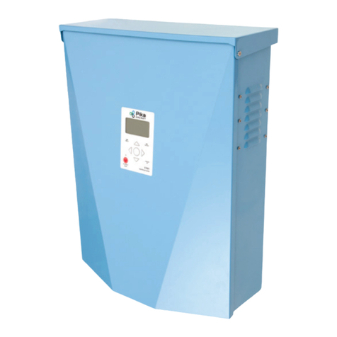
PIKA X7602 User manual

M00008-24
Installation Manual
Pika Islanding Inverter
X7602/X11402
Part of the Pika Energy Island™

Islanding Inverter
Serial Number:
RCP Number:

3Islanding Inverter Installation Manual M00008-24
www.pika-energy.com

4 Islanding Inverter Installation Manual M00008-24
Table of Contents
Table of Contents
Section 1: Introduction 6
About This Manual 6
Symbols used in this Manual 6
About Pika Islanding Inverters: X7602/X11402 7
Section 2: Safety Specications 8
General Warnings 8
Safety Shutdown 9
Section 3: Mounting the Inverter 10
Section 4: Electrical Connections 12
Wiring Guidelines 13
Knockout Dimensions and Locations 14
Grounding 16
DC Wiring 17
AC Wiring 18
Protected Loads 19
Connecting Ethernet 21
Connecting Current Transformers (CTs) 22
Section 5: External Transfer Switches 25
Controlling an Automatic Transfer Switch (ATS) 26
Section 6: Other Accessories 29
External Safety Shutdown Switch 29
Beacon 29
Tech. Service Connection 29
Gen Sense and Gen Start Terminals 29
Section 7: Compliance 30
Note on DC Wiring and NEC 30
Safety Shutdown 30
Voltage and Frequency Trip Thresholds 30

5Islanding Inverter Installation Manual M00008-24
Table of Contents
Section 8: System Congurations 32
Required Equipment 32
Enabling Islanding 32
Section 9: Commissioning and Setup 33
Commissioning the System 33
Registering Your System on REview 37
REbus Cross Talk Between Multiple Inverters 38
PLM Channels 38
Section 10: Service and Maintenance 40
Removing the Wiring Compartment Cover 41
Common Issues 43
Recovery From an Error State 43
Technical Support Information 43
Section 11: Technical Reference 45
Terminal Torques 45
Wire Sizing 45
Section 12: Specications 46
Quick Reference 46
Detailed Ratings 47
Notes 48

6 Islanding Inverter Installation Manual M00008-24
Section 1: Introduction
About This Manual
Use This Document for the Following Serial Numbers
Symbols used in this Manual
WARNING:
CAUTION: Presents information to prevent damage to this product
EARTH

7Islanding Inverter Installation Manual M00008-24
About Pika Islanding Inverters: X7602/X11402
energy.com.
50 A.
Grid LoadsInverterBatterySolar
Fig 1. Example Energy Island

8 Islanding Inverter Installation Manual M00008-24
Section 2: Safety Specications
General Warnings
WARNING:
SHOCK RISK:
WARNING:
and caution markings in this guide and installation manual. Consult
WARNING:
WARNING:
WARNING: Connecting the Pika Energy Island to the electric utility
WARNING:
equipment or other medical equipment or devices.
WARNING:
safety instructions.

9Islanding Inverter Installation Manual M00008-24
Safety Shutdown
more information.
To enter a Safety Shutdown, press and hold the red button on the front of the inverter. The
Safety Shutdown LED will illuminate and the LCD screen will indicate a Safety Shutdown has
been initiated.
WARNING:

10 Islanding Inverter Installation Manual M00008-24
Section 3: Mounting the Inverter
different stud spacings.
CAUTION:
16”
1 1/2”
TOP OF ENCLOSURE
2 3/8”
Fig 6. X7602/X11402 Mounting Bracket

11Islanding Inverter Installation Manual M00008-24
4”
28”
Floor
Wall
SideFront
8”
28.5”
36”
8”
19.25” 8.5”20”
8”
24.5”
Fig 5. X7602/X11402 Mounting Clearances
Wall
Screws x 2
3. Install Internal Mounting Screws2. Hang Inverter on Bracket1. Install Bracket
Screws x 2
Bracket
Fig 7. X7602/X11402 Hanging Bracket

12 Islanding Inverter Installation Manual M00008-24
Section 4: Electrical Connections
WARNING:
Ensure no dangerous voltages are present on conductors and terminals
WARNING:
safety instructions.
are complete.
DC Side
380 VDC REbus Nanogrid
AC Side
240 VAC Grid Power
30A
DC Breakers 50A2P
Pika Energy Inc
35 Bradley Drive, Unit 1
Westbrook Maine, 04092
Example Energy Island System
Revision: 1.3.1
Revision date: 20180311
For project-specific engineering support
WARNING
- Use 12ga wire at minimum for DC side.
- Never exceed 25A per 30A internal breaker.
- Maximize input to each PV Link when sizing sub-arrays
FOR REFERENCE ONLY: System must be designed and installed by a licensed contractor or engineer in accordance with NEC and local building codes.
Refer to Pika String Sizing Guide for solar module configurations with PV Link.
Islanding
Inverter
Pika
Smart Battery
AC Main Panel
Grid
Protected Loads
Current Transformers
PV Link
PV Link
PV Link
PV Link
4 PV Links
Smart Battery
Protected Loads Panel
Fig 8. Example of 10kW Energy Island with Smart Battery and Protected Loads

13Islanding Inverter Installation Manual M00008-24
Wiring Guidelines
on page 45.
securely fastened.
REbus Bi-Directional
DC Input Terminals
PV Link and Smart Battery
Protected Loads
Terminals
Grounding Bar
Internet Connection Gen Sense/Gen Start
(Not Yet Active)
DC Main Fuses
AC Grid Connection
Terminals
Accessory Ports
CTs, ATS Control, Shutdown
Protected Loads
Breaker (50A)
Fig 9. X7602/X11402 Islanding Inverter wiring compartment

14 Islanding Inverter Installation Manual M00008-24
Knockout Dimensions and Locations
Combination Knockout Size Quantity
6
7

15Islanding Inverter Installation Manual M00008-24
5.517
140.13
5.910
150.13
2.638
67
1.654
42
1.969
50
2.819
71.60
2.212
56.18
1.374
34.91
2.165
55
2.165
55
1.083
27.50
2.165
55
1.929
49
1.875
47.63
1.811
45.99
.119
3.01
1.648
41.85
2.427
61.64
2.165
55
2.274
57.77
1.405
35.69
Fig 10. X7602/X11402 knockout conguration

16 Islanding Inverter Installation Manual M00008-24
Grounding
of the installer.
Grounding Bar Wiring Terminals
Wire Size (AWG) Torque (Nm) Torque (lb-in)
4 - 6 5 45
8 4.5 40
10 4 35
WARNING:

17Islanding Inverter Installation Manual M00008-24
DC Wiring
WARNING:
WARNING:
conductors simultaneously.
DC Wiring Terminals
Wire Size Terminal Temp range Wire Min Temp
Rating Torque
-40 to 130ºC 90ºC
Pro Tip: You may connect any REbus device to any one of the bidirectional inputs, or up to 30A of
parallel devices. In practice, this means you can connect one REbus compatible smart battery to
each input, or up to three PV Links. Always follow applicable codes when calculating ampacities and
selecting and installing wiring and overcurrent protection.
CAUTION:
CAUTION:

18 Islanding Inverter Installation Manual M00008-24
AC Wiring
AC Wiring Terminals
Wire Size Terminal Temp Range Wire Min Temp
Rating Torque
2 to 16 mm2
90ºC
AC Grid Connection
Protected Loads
N1
L1
L2
N
Protcd.
L3
(3p)
White
Black
Red
White
Black
Red
Blue
L1
Protcd.
L2
Protcd.
Fig 11. AC Terminal Block. Use the blue L3 terminal only with X11402.

19Islanding Inverter Installation Manual M00008-24
AC Wiring
Protected Loads
CAUTION:
damage.
grid outage.
of a second.
Note: The Islanding Inverter cannot provide full three-phase power at the Protected Loads terminals.
Contact Pika Energy for design assistance when using the X11400-series to provide backup power.
Protected Loads
Panel
Pika Smart Battery
Islanding Inverter
Internal 50A Protected Loads Breaker
AC Main
Panel
PV Array
Fig 20. Single Inverter Backup Installation with Protected Loads Panel

20 Islanding Inverter Installation Manual M00008-24
Pro Tip: If your system does not include battery storage but you expect to add batteries in the future,
you can install a Protected Loads panel at the same time you install the inverter. The Protected Loads
panel will be fed by the grid through the inverter while the system operates in Grid Tie mode.
Protected Loads
Panel
Islanding Inverter
Internal 50A Protected Loads Breaker
Main AC
Panel
PV Array
Fig 19. Protected Loads Panel Installed -- Add Batteries Later
CAUTION:
CAUTION:
Other manuals for X7602
1
This manual suits for next models
1
Table of contents
Other PIKA Inverter manuals
Popular Inverter manuals by other brands

Phaesun
Phaesun Tre King quick guide

York
York YHUJYH(024-060)BAR(S)XA-X(Y) installation manual

ABB
ABB TRIO-50.0-TL-OUTD-US Quick installation guide

ULTRA BRIGHT
ULTRA BRIGHT UB-SFPL-S-4 Series instructions

Huawei
Huawei SUN2000-200KTL-H2 quick guide

Tektronix
Tektronix PPG3000 Series Declassification and security instructions

Sungrow
Sungrow SG3125HV-20 System manual

Invertek Drives
Invertek Drives OPTIDRIVE E3 user manual

MidNite Solar
MidNite Solar MNKID-B manual

Generac Power Systems
Generac Power Systems Guardian 004373-3 owner's manual

Growatt
Growatt WIT 28-55K-A-US L2 quick guide

Westinghouse
Westinghouse 5300 Running Watts user manual